Ados A100E User manual
492-MTU10006 Rev. 4 Page 1 of 49
INSTRUCTION
MANUAL
A100E
SW Version 1.06
5
4Changes to Rev 1.6 22/11/00 Golinelli G. Paulitti G.
3Changes to Rev 1.5 10/04/99 Golinelli G. Paulitti G.
2Changes to Rev 1.2 (password) 15/06/98 Golinelli G. Paulitti G.
1MODBUS protocol 02/03/98 Golinelli G. Paulitti G.
0Issue 27/11/97 Golinelli G. Paulitti G.
492_4 Rev. Subject of the revision Date Prepared Checked Approved

ADOS S.R.L. Buccinasco (MI)
492-MTU10006 Rev. 4 Page 2 of 49
Contents
1. INTRODUCTION ....................................................................................................................... 4
1.1 General................................................................................................................................... 4
1.2 Versions/options ..................................................................................................................... 4
1.3 Documentation....................................................................................................................... 4
1.4 Equipment marking description............................................................................................. 5
2. OPERATING SPECIFICATIONS .............................................................................................. 6
2.1 Technical data ........................................................................................................................ 6
3. INSTRUMENT OPERATIONS ................................................................................................. 7
3.1 Turning on the instrument...................................................................................................... 7
3.2 Display indication................................................................................................................... 8
3.3 Tare ......................................................................................................................................... 8
3.4 Manual Zero........................................................................................................................... 8
3.5 Automatic Zero Tracking ....................................................................................................... 8
3.6 LED status indicators ............................................................................................................ 9
3.7 Key functions ......................................................................................................................... 9
3.8 Switch.....................................................................................................................................11
3.9 Self diagnostic .......................................................................................................................11
3.9.1 Configuration memory integrity check .................................................................................11
3.9.2 Configuration parameter integrity check ..............................................................................12
3.10 Output relay operation......................................................................................................... 13
3.11 SERIAL INTERFACE MANAGEMENT.......................................................................... 15
3.11.1 Primary serial interface ......................................................................................................15
3.11.2 RS485 interface.................................................................................................................15
3.11.3 Continuous modality ...........................................................................................................16
3.11.4 Bi-directional modality........................................................................................................16
3.11.5 Print On Request modality..................................................................................................18
3.11.6 Bi-directional modality with MODBUS protocol...................................................................19
3.11.7 Auxiliary serial interface.....................................................................................................24
4. INSTALLATION........................................................................................................................ 25
4.1 Material receiving ............................................................................................................... 25
4.2 Instrument mounting ............................................................................................................ 26
4.3 Connections .......................................................................................................................... 27
4.3.1 Wiring the instrument to the protective earthing system ........................................................28
4.3.2 Power supply connection....................................................................................................28
4.3.3 Load cell connection ..........................................................................................................29
4.3.4 Relay output connection .....................................................................................................30
4.3.5 Serial port connection.........................................................................................................31
5. MAINTENANCE....................................................................................................................... 32
5.1 Preventive maintenance ...................................................................................................... 32
5.2 Corrective maintenance....................................................................................................... 32
6. INSTRUMENT CONTROL ..................................................................................................... 33
6.1 Introduction.......................................................................................................................... 33
6.2 Control function selection.................................................................................................... 34
6.2.1 Password..........................................................................................................................35

ADOS S.R.L. Buccinasco (MI)
492-MTU10006 Rev. 4 Page 3 of 49
6.2.2 Keyboard time out .............................................................................................................35
6.3 Operating parameter configuration..................................................................................... 36
6.3.1 Operating parameter selection ............................................................................................36
6.3.2 Modifying the value of the operating parameters ..................................................................37
6.3.3 Graduation.........................................................................................................................38
6.3.4 Resolution .........................................................................................................................38
6.3.5 Decimal point ....................................................................................................................38
6.3.6 Averages ..........................................................................................................................38
6.3.7 Zero limit...........................................................................................................................40
6.3.8 Motion band ......................................................................................................................40
6.3.9 Zero tracking limit ..............................................................................................................40
6.3.10 Primary serial port .............................................................................................................41
6.3.11 Auxiliary serial port............................................................................................................41
6.3.12 Transmission delay.............................................................................................................41
6.3.13 Receiver Time out .............................................................................................................41
6.3.14 Address on RS485 .............................................................................................................41
6.3.15 Baud rate ..........................................................................................................................41
6.3.16 Relay function ...................................................................................................................43
6.3.17 Relay threshold ..................................................................................................................43
6.3.18 Dead Band........................................................................................................................43
6.4 Calibration............................................................................................................................ 44
6.4.1 Zero calibration..................................................................................................................45
6.4.2 Span calibration .................................................................................................................46
6.5 Test....................................................................................................................................... 47
6.6 System Initialization............................................................................................................. 48
6.6.1 Switch controlled initialization..............................................................................................48
7. INSTRUMENT CONFIGURAZIONE TABLE....................................................................... 49

ADOS S.R.L. Buccinasco (MI)
492-MTU10006 Rev. 4 Page 4 of 49
1. INTRODUCTION
1.1 General
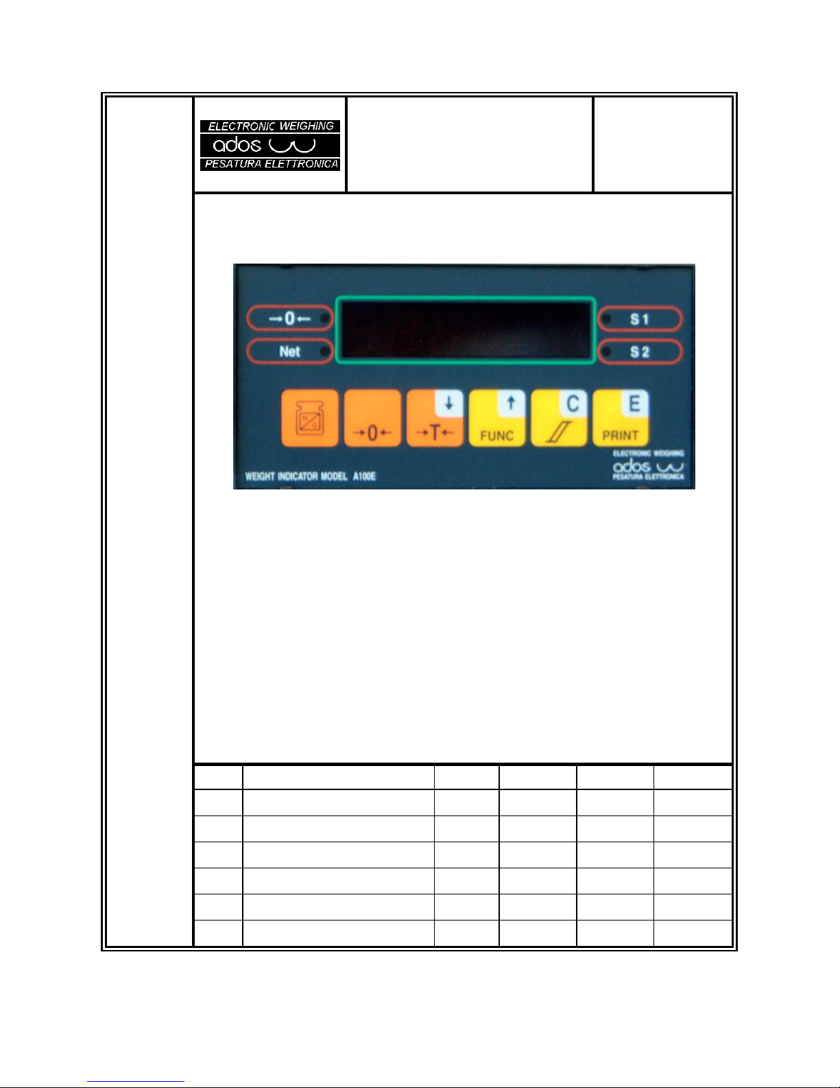
The A100E instrument is a microprocessor based weight amplifier and indicator.
It was designed to connected to a maximum of 6 load cells (350 ?bridge), connected in parallel.
The keyboard can be used to carry out all the programming, configuration and calibration functions.
A series of display messages guides the operator through all the phases.
A series of options sets up the instrument for the main functions related to electronic weighing.
1.2 Versions/options
A
1
0
0
E
X
X
Type of power supply 1 = 115 Vac - 2 = 230 Vac
3 = 24 Vac - 4 = 24 Vcc
5 = 12 Vcc
Version set up for management: Transpallet (T)
SAMPLE ORDER
A100E wired for 230 Vac operation: A 1 0 0 E 2
1.3 Documentation
This technical manual is relevant to the base version of the instrument.
The technical manual is relevant to the transpallet management version is 538-MTU10007.
ADOS S.R.L. Buccinasco (MI)
492-MTU10006 Rev. 4 Page 5 of 49
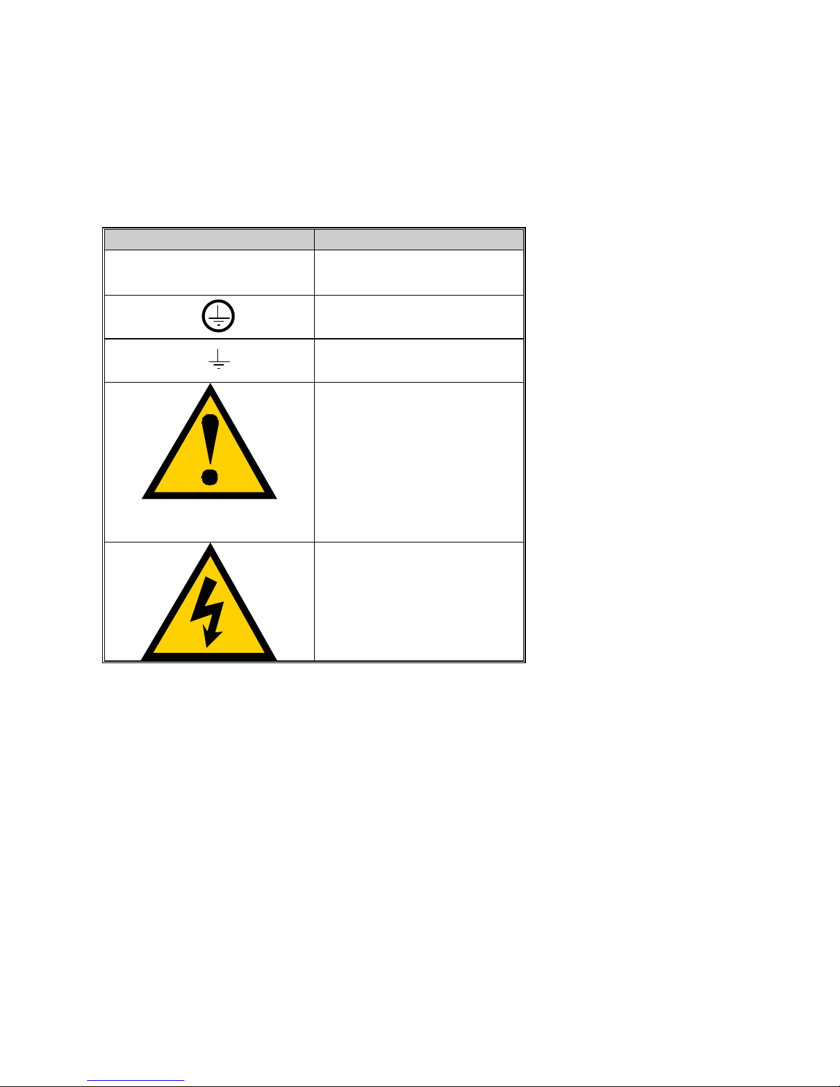
1.4 Equipment marking description
A100E is marked with symbols compliant with European Standard 61010-1 (April 1993).
SYMBOL DESCRIPION
?Alternating current
Protective conductor terminal
Earth (ground) terminal
Caution (refer to accompanying
documents)
Caution, risk of electric shock

ADOS S.R.L. Buccinasco (MI)
492-MTU10006 Rev. 4 Page 6 of 49
2. OPERATING SPECIFICATIONS
2.1 Technical data
Power supply 230 Vac 50/60 Hz -15%...+10%
120 Vac 50/60 Hz (optional) -15%...+10%
Consumption 10VA (15 VA MAX.)
Fuse 230 Vac: 80 mA Time lag T
120 Vac: 160 mA Time lag T
+ 12 Vdc: 500 mA Fast
+ 24 Vdc 630 mA Fast
Operating temperature from - 10 ?C to + 40 ?C
Storage temperature from - 40 ?C to + 70 ?C
Relative humidity 95% non-condensing
Load cell power supply 8 Vdc (short-circuit proof)
Maximum current 90 mA (4 x 350 ?load cells in parallel)
Electric connection 4 wires
Analog signal 0.5 - 2.5mV/V
Resolution 0.8 ?V/Grad
Conversion speed 55 conversion/sec
Graduation 1000-2000-3000-4000-5000
Resolution 1-2-5-10-20-50
Off scale limit (UL/OL) 20% of full scale load
Display five (5) digits LED
Polarity sign -
Keyboard six (6) keys
Status indicators four (4) LED indicators
Decimal point user defined: 0 - 0.0 - 0.00 - 0.000 - 0.0000
Zero tracking user defined (0.5 - 1 - 2 - 5 - 10 div/s)
AZM aperture user defined (OFF - 1.9% - 100% of F.S.)
Motion band user defined (OFF - 0.5 - 1 - 2 - 5- 10- 20 div)
Serial outputs main output RS232 or RS485 Half-duplex, aux
output RS232, Tx only
Digital outputs two (2) base relay outputs and eight (8) extra
Contact rating 0.5 A @ 24 Vdc
Housing self extinguishing NORYL UL 94 V- (Black) for
front panel mounting according toDIN 43700
Dimensions 72 x 144 x 129 mm
Drilling 68 x 138 mm
Weight 0.7 Kg
Mounting Front panel mounting with two holding brackets
mounted on the sides of the enclosure
ADOS S.R.L. Buccinasco (MI)
492-MTU10006 Rev. 4 Page 7 of 49
3. INSTRUMENT OPERATIONS
3.1 Turning on the instrument
When the instrument is turned on, the primary display indicates the following, at intervals of about two
seconds:
A D O S
A100E
V E R 1. 0 6 (Revision of the installed software)
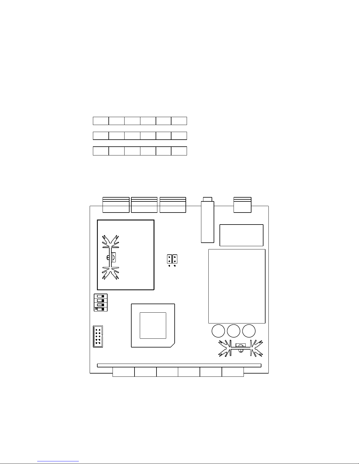
Figure 1
SW1
JP2-JP1

ADOS S.R.L. Buccinasco (MI)
492-MTU10006 Rev. 4 Page 8 of 49
3.2 Display indication
Under normal operating condition (i.e. during weighing) the display shows the value of the weight, using the
following criteria:
?leading zeroes will presented as blank
?the polarity “minus” (in case of negative values) is indicated in the leftmost digit
?if the negative value is composed of six digits (for example -132400), the leftmost digit will show
alternatively the “minus” and the fifth digit value.
Indication limits are the following:
lower limit: - 20% of full scale
higher limit: 120% of full scale
if the weight is under the lower limit the following will be displayed:
? ? UL? ?
if the weight is over the upper limit (or if the load cell signal is higher than 20 mV the following will be
displayed:
? ? OL? ?
3.3 Tare
Pressing the Tkey (with the instrument setted in the Net mode and the weight stable) the instrument will
copy the current value of the gross weight into the tare value, thus clearing the net weight value.
The Tare command can also be issued from serial line.
3.4 Manual Zero
Value of gross weight can be manually zeroed out by pressing the >0< key if the instrument is setted in
GROSS, the weight is stable and the total zeroed value is lower than the limit defined by parameter “0
LIMIT”.
The Zero command can also be issued from serial line.
The effect of a ZERO command is a translation of the response curve of the instrument, without affecting its
slope: if 2000 Kg are zeroed out in a system having 5000Kgof full scale, the new full scale will become
3000 Kg.
3.5 Automatic Zero Tracking
Automatic Zero tracking can be achieved if the value of weight is stable, the total zeroed value is lower than
the limit defined by parameter “0 LIMIT” and the rate of change of weight is lower than value defined by
parameter “Zero Tracking”.

ADOS S.R.L. Buccinasco (MI)
492-MTU10006 Rev. 4 Page 9 of 49
3.6 LED status indicators
The indications provided by the signal LED’s located on the front panel of the instrument are explained
below:
?0?
The LED is on when the value of the weight is 0 and is stable within 1/4 of a division.
The indication is available under gross weight and net weight conditions.
N
The LED is on when the instrument displays the net weight (gross weight minus the tare).
Pressing the Tkey in NET the instrument copies the current value of the gross weight into the tare value,
thus clearing the value of the net weight.
S1
The LED is on when relay 1 is energized.
S2
The LED is on when relay 2 is energized.
3.7 Key functions
ZERO
Press this key (with the instrument in the Gross mode and the weight stable) to clear the divisions indicated
on the display within the limits set by the configuration of the “AZM limit” parameter.
G/N
Press this key to toggle between the Gross and Net condition.
T
Press this key (with the instrument in the Net mode and the weight stable) the instrument to copy the
current value of the gross weight into the tare value, thus clearing the net weight value.
F
Press this key to enter the configuration modality.
C
Press this key to enter the threshold configuration modality.
E

ADOS S.R.L. Buccinasco (MI)
492-MTU10006 Rev. 4 Page 10 of 49
Press this key to perform a print request on the primary serial port. The request takes effect only if the
serial port is configured for “print on request”.
ADOS S.R.L. Buccinasco (MI)
492-MTU10006 Rev. 4 Page 11 of 49
3.8 Switch
The instrument is equipped with a DIP switch banck having the following functions:
Position Function Normal State
SW1-1 Not used OFF
SW1-2 Not used OFF
SW1-3 Not used OFF
SW1-4 Initialization of configuration parameter memory
Can be used as an alternative to the normal init procedure.
See “Initialization” paragraph for operation details.
OFF
3.9 Self diagnostic
A100E transmitter has a number of built-in self diagnostic features intended to improve the overall
operating safety.
Generally speaking, when a fault condition is detected, the instrument is driven to a safety condition
deenergizing alarm relays.
Display indications are provided to help in fault finding.
3.9.1 Configuration memory integrity check
Check is carried out at power on.
If the configuration memory is found defective, the power on sequence will not be completed , all relays
are driven to alarm condition (deenergized) and the serial line is deactivated.
A forced reconfiguration to default is then performed and the primary display shows the following message:
I N I T Blinking
The transmitter stays in this condition as long as a key is pressed by operator to acknowledge the situation.
The instrument must be reconfigured and recalibrated.

ADOS S.R.L. Buccinasco (MI)
492-MTU10006 Rev. 4 Page 12 of 49
3.9.2 Configuration parameter integrity check
Check is carried out every operating cycle.
If a configuration parameter is found defective, the message “ER XX” will be reported on display for half a
second every two seconds, where XX is the code of the wrong parameter, according to the following table:
CODE Meaning Effect on indicator Resolution
ER 01 Error in the CALIBRATION
parameters
Relays are deenergized.
Error code is reported on serial line.
Instrument must be
recalibrated
ER 02 Error in the TARE
parameters
Relays are deenergized.
Error code is reported on serial line.
Redo tare
ER 03 Error in DIVIS e SENSIB
parameters
Relays are deenergized.
Error code is reported on serial line.
Reconfigure parameters
ER 04 Error in
AVER and DEC. PNT
No effect
Error code is reported on serial line.
Reconfigure parameters
ER 05 Error in LIM AZM -
MOTION - ZERO
TRACKING parameters
Relays are deenergized.
Error code is reported on serial line.
Reconfigure parameters
ER 06 Error in SER P - SER A-
BAUD - DLY SND - DLY
RCV - AD485 parameters
No effect Probably malfunctions on
serial line operation. The error code is
reported on the serial line
Reconfigure parameters
ER 07 Error in the RELAY 1
parameters
Relay 1 is deenergized.
Error code is reported on serial line.
Reconfigure parameters
ER 08 Error in the RELAY 2
parameters
Relays are deenergized.
Error code is reported on serial line.
Reconfigure parameters

ADOS S.R.L. Buccinasco (MI)
492-MTU10006 Rev. 4 Page 13 of 49
3.10 Output relay operation
The action of the relay depends on the weight condition (gross or net) defined in the configuration phase
independently from what is indicated on the display. Therefore, the user can switch the display selection as
required without accidentally enabling the thresholds.
The relay returns to “normal” conditions when the weight value again drops below the value calculated as
the sum of the threshold value and the defined dead band value.
Each relay can be configured to operate in one of the following modes:
Off
The relay is permanently disabled.
Closing on Gross
The relay is de-energized (and the output contact opened) for all the gross weight values lower than the
threshold set in the configuration. The relay is energized (and the output contact closed) for all the gross
weight values greater than or equal to the threshold set in the configuration.
Closing on Net upon Loading
The relay is de-energized (and the output contact opened) for all the gross net values lower than the
threshold set in the configuration. The relay is energized (and the output contact closed) for all the net
weight values greater than or equal to the threshold set in the configuration.
Closing on Net upon Unloading
The relay is de-energized (and the output contact opened) for all the negative net weight values lower than
(in terms of absolute value) the threshold set in the configuration. The relay is energized (and the output
contact closed) for all the negative net weight values greater than or equal to (in terms of absolute value) the
threshold set in the configuration.
Example: if the threshold set is 1250, the relay is de-energized for positive values and for the negative
values from -1 to -1249. The relay is energized for values ranging between -1250 and -F.S.
Opening on Gross
The relay is energized (and the output contact closed) for all the gross weight values lower than the
threshold set in the configuration. The relay is de-energized (and the output contact opened) for all the
gross weight values greater than or equal to the threshold set in the configuration.
Opening on Net upon Loading
The relay is energized (and the output contact closed) for all the net weight values lower than the threshold
set in the configuration. The relay is de-energized (and the output contact opened) for all the net weight
values greater than or equal to the threshold set in the configuration.
Opening on Net upon Unloading
The relay is energized (and the output contact closed) for all the net negative weight values lower than (in
terms of absolute value) the threshold set in the configuration. The relay is de-energized (and the output
contact opened) for all the net negative weight values greater than or equal to less (in terms of absolute
value) the threshold set in the configuration.

ADOS S.R.L. Buccinasco (MI)
492-MTU10006 Rev. 4 Page 14 of 49
Example: if the threshold set is 1250, the relay is energized for positive new values and for all the negative
values from -1 to -1249. The relay is de-energized for values ranging between -1250 and -F.S.
ADOS S.R.L. Buccinasco (MI)
492-MTU10006 Rev. 4 Page 15 of 49
3.11 SERIAL INTERFACE MANAGEMENT
3.11.1 Primary serial interface
The primary serial line is available in both the RS232 and RS485 mode.
The factory configuration is RS232 (see Figure 1).
1RS485
2
3RS232
JP2 JP1
JP1 e JP2 closed in position 1-2 RS485 mode
JP1 e JP2 closed in position 2-3 RS232 mode
If the instrument is used in the RS485 modality, an integrated circuit MAX483E must be mounted in the
socket U4 (see Figure 1).
The primary serial line can be configured in one of the following operating modes:
?Off
?Continuous transmission
?Bi-directional (eventually with address for 485)
?Print On request from keyboard command or external button
The transmission parameters of the primary and auxiliary line are :
?8 bit - No Parity - 1 Stop
The primary line speed can be configured as follows:
?9600
?4800
?2400
?1200
3.11.2 RS485 interface
The instrument can control an RS485 line as an alternative to the main line RS232.
The physical interface is on two balanced wires.
The logic protocol is half duplex master/slave and the instrument responds as a slave.
?
?
?
?
?
?

ADOS S.R.L. Buccinasco (MI)
492-MTU10006 Rev. 4 Page 16 of 49
For the RS485 line connection the instrument must be equipped with the driver in U8 and the jumper Z8
must be positioned in 1-2.
The RS232 or RS485 selection is determined by the value of the configuration parameter “address 485”: if
the parameter is 0 the instrument controls the protocol RS232, otherwise it controls the protocol RS485.
The modality is activated independently from the physical configuration of the board, therefore it is possible
to operate with messages addressed also on the physical line RS232.
The data structure is the same, with the only addition of the addressed field (two characters from “01” to
“32”) in reception and in transmission.
3.11.3 Continuous modality
The instrument continuously transmits a string with the following format:
<STX><POL><WEIGHT><K><L/N><STATUS><CR><LF>
where:
<STX> “Start Of Test” (Hex 02) character
<POL> “Blank” (Hex 20) or “-” (Hex 2D) character to indicate the polarity of the data
< WEIGHT > string of 7 numerical characters (Hex 30 .. 39) representing the weight shown on display
and possibly with “.” (Hex 2E)
<K> “K” (Hex 4B)
<G/N> “G” (Hex 47) or “N” (Hex 4E) character to indicate the Gross/Net state
<STATUS> one of the following characters:
“Blank” (Hex 20) System under normal operating conditions
“I” (Hex 43) Instrument to calibrate (invalid data)
“S” (Hex 43) Instrument being configured
“O” (Hex 4F) Instrument off scale
“M” (Hex 4D) Moving weight
<CR> “Carriage Return” character (Hex 0D)
<LF> “Line Feed” character (Hex 0A)
3.11.4 Bi-directional modality
In this modality the instrument transmits the data only when requested by an external system.
The protocol can be used with RS232 lines and with RS485 half-duplex lines. The selection depends on
the configuration value of the RS485 address: if other than zero, the instrument controls the value of the
address field in the received data and inserts the address field in the transmitted data.
The request string has the following format

ADOS S.R.L. Buccinasco (MI)
492-MTU10006 Rev. 4 Page 17 of 49
<STX><ADDH><ADDL><CMD><DATA><CR><LF>
where:
<STX> “Start Of Text” (Hex 02) character
<ADDH> 485 address character - high (Hex 30 .. 32)
<ADDL> 485 address character - low (Hex 30 .. 39)
<CMD> Command identification character
<DATA> Any data related to the command
<CR> “Carriage Return” (Hex 0D) character
<LF> “Line Feed” (Hex 0A) character
Commands from host to A100E
P (hex 50) weight request command. A string is transmitted with the same format of what is
described for continuos mode. If 485 address is other than zero, the <ADDR>
field is inserted after STX
p (hex 70) weight request command. A string is transmitted with the following format:
<STX><G_P><GROS_W><T_P><TARE_W><K/L><L/N><STATO><CR><LF
where:
<G_P><GROSS_W> polarity and value of the gross weight (8 char)
<T_P><TARE_W> polarity and value of the tare weight (8 char)
If 485 address is other than zero, the <ADDR> field is inserted after STX
l (hex 5C) gross weight request command. A string is transmitted with the same format of what
is described for continuos mode, but always sending the value of the gross weight,
independently from display selection.
If 485 address is other than zero, the <ADDR> field is inserted after STX
ZZERO command. The command is always accepted, even if the instrument is in
Net mode or the Motion is ON. The command is effective only if the gross weight
is lower then the defined AZM limit, otherwise en error message is issued
GGROSS command. The command is always accepted.
NNET command. The command is always accepted.
TTare execution command. The command is always accepted, even if the instrument
is in Net mode or the Motion is ON.
SRn request for the value of the set point “n”, with “n” equal to 1 or 2
The answer message has the following format:
<STX><SRnt(0001234)
where:
n is the set point number
tis the code of the relay function
0 = OFF
1 = Closing on Gross
2 = Closing on Net upon Loading
3 = Closing on Net upon Unloading
4 = Opening on Gross
5 = Opening on Net upon Loading
6 = Opening on Net upon Unloading

ADOS S.R.L. Buccinasco (MI)
492-MTU10006 Rev. 4 Page 18 of 49
0001234 is the value of the set point (7 char including decimal point, if any)
SEnt(ddddddd) set value of the set point “n” to type “t” and to value “dddd”
3.11.5 Print On Request modality
The weight string is transmitted like in the continuous transmission when operator pressing the “E” key
(when the instrument is not being configured).

ADOS S.R.L. Buccinasco (MI)
492-MTU10006 Rev. 4 Page 19 of 49
3.11.6 Bi-directional modality with MODBUS protocol
The RTU version of MODBUS is used.
Received and transmitted frame structure
General frame structure is as follows:
ADDRESS FUNCTION DATA CHECK
8 bits 8 bits N x 8 bits 2 x 8 bits
ADDRESS 8 bit defining the slave address and ranging from 1 to 32
FUNCTION 8 bit defining the required function.
The functions supported by A100E are the following
Code 03 Read Holding Registers
Code 05 Force Single Coil
Code 06 Preset Single Register
Code 16 Preset Multiple Registers
DATA All data relevant to the specific function
CHECK CRC-16 (Cyclic Redundancy Check) frame validation
Exception responses
When A100E receives a request involving illegal functions or illegal data an exception response is generated
containing address, function code, error code and checksum.
To indicate that the response is a notification of an error, the high order bit of the function code is set to “1”.
Supported error code are:
01 Illegal function. The message function received is not an allowable action for the
addressed slave.
02 Illegal data address. The address referenced in the data field is not an allowable
address in the address slave location
03 Illegal data value. The value referenced in the data field is not allowable in the
addressed slave location
A100E supported functions
For a complete description of MODBUS available functions, please refer to detailed MODBUS
documentation.
Function 03 - Read Holding Registers

ADOS S.R.L. Buccinasco (MI)
492-MTU10006 Rev. 4 Page 20 of 49
Allows the host to obtain the binary value of the content of A100E registers
All registers can be transferred in a single read request.
The below example reads registers 0 through 2 from slave 01:
ADDR FUNC START
REG HI
START
ERG
LOW
# OF
ERG HI
# OF
ERG
LOW
CHECK
01 03 00 00 00 03 05 CB
Slave answer is as follows:
ADDR FUNC BYTE
COUNT
REG
0
HI
REG
0
LOW
REG
1
HI
REG
1
LOW
REG
2
HI
REG
2
LOW
CHECK
01 03 06 00 0F 00 00 01 C0 74 B4
Value of register 0 is 15, register 1 is 0 and register 2 is 448.
Function 05 - Force Single Coil
Allows the host to force a single coil. In A100E the command is used to issue a ZERO, G/N, TARE or
POF reset command.
If the ZERO cannot be done (not enabled or weigh higher than the allowable limit) an “Illegal Data Value”
exception response will be generated
The below is a valid example:
ADDR FUNC COIL
#
HI
COIL
#
LOW
DATA
VALUE
HI
DATA
VALUE
LOW
CHECK
01 05 00 00 FF 00 8C 3A
The normal response is to retransmit the query message:
ADDR FUNC COIL
#
HI
COIL
#
LOW
DATA
VALUE
HI
DATA
VALUE
LOW
CHECK
01 05 00 00 FF 00 8C 3A
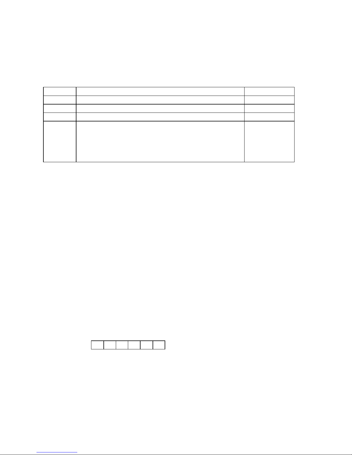
Function 06 - Preset Single Register
Allows the host to modify the contents of an holding register
The below example preset register 12 of slave 01 with 54:
ADDR FUNC REG REG DATA DATA CHECK
Table of contents
Other Ados Accessories manuals


Popular Accessories manuals by other brands


ekwb
ekwb EK-FC1080 GTX Ti FTW3 installation manual

iNels
iNels RFTI-20 quick start guide

Alarm Controls Corporation
Alarm Controls Corporation SREX-100 operating instructions

Diamond Tech International
Diamond Tech International FIREWORKS Beginners Beadmaking Kit Instructional manual

Office Star Products
Office Star Products ProLine II PRDPOW1 operating instructions

Flowserve
Flowserve IPS Smart RTU User instructions