FINO RS 50 General instructions

F
F
Fi
i
iN
N
NO
O
O
S
S
ST
T
TE
E
EA
A
AM
M
M
G
G
GE
E
EN
N
NE
E
ER
R
RA
A
AT
T
TO
O
OR
R
RS
S
S
I
I
IN
N
NS
S
ST
T
TA
A
AL
L
LL
L
LA
A
AT
T
TI
I
IO
O
ON
N
N,
,
,
O
O
OP
P
PE
E
ER
R
RA
A
AT
T
TI
I
IO
O
ON
N
N
A
A
AN
N
ND
D
D
M
M
MA
A
AI
I
IN
N
NT
T
TE
E
EN
N
NA
A
AN
N
NC
C
CE
E
E
M
M
MA
A
AN
N
NU
U
UA
A
AL
L
L

FINO®Installation, Operation & Maintenance Manual
1
We manufacture steam generators for any steam bath need. They are the result
of many years of continued research. From the smallest residential unit to the
largest commercial unit, our products are manufactured to the same rigid
quality standard. We also custom build for those specialized applications e.g.
yachts, Recreational Vehicles (RV’s), specialized home or commercial use,
executive fitness rooms, club house, hotels, resort, and high end spas.
Steam Bath® steam generator has been tested and approved by CSA and listed
with UL, also manufactured as per ISO 9001:2008 Quality Management System,
so you are assured of the highest quality and safety standard.
This manual is a comprehensive guide to proper installation, operation and
maintenance of your ® RS, CS, and RV Series steam units.
It covers the following Models:
RS Series CS Series CS Large RV Series
RS 50 CS 11 CS 18 RV 9
RS 100 CS 12 CS 21 RV 13
RS 150 CS 13 CS 24 RV 15
RS 250 CS 15 CS 30 RV 18
INTRODUCTION 1
SPECIFICATION SHEET 2
INSTALLATION GUIDE 3
GENERAL INSTALLATION INSTRUCTIONS 4
SAFETY TIPS 5
BASIC TROUBLE SHOOTING GUIDE 6
FINO CONTROL - Glass Touch 7
LED BUTTONS 8
FILTRATION 9
SCENT DISPENSER 9
TABLE OF CONTENTS
INTRODUCTION

FINO®Installation, Operation & Maintenance Manual
2
MODEL
NO.
KW
MAX
Volts/
Phase/
Amps
Wire
Gauge
CU FT
RANGE
MAX DIM
L x W x H
(w/drain)
NET
WEIGHT
RV9 8.5 240
/
1
/
38 8
50-375
15”x5”x12” 24 lbs
RV13 13 240
/
1
/
55 6
50-600
15”x8”x12” 30 lbs
RV15 15 240
/
1
/
63 4
50-700
15”x8”x12” 30 lbs
RV18 18 240
/
1
/
75 3
50-800
15”x8”x12” 30 lbs
RS50 3.0 240
/
1
/
13 12
50-90
23”
x
7”
x
10” 25 lbs
RS100 4.5 240
/
1
/
19 12
90-150
23”
x
7”
x
10” 25 lbs
RS150 6.5 240
/
1
/
27 10
150-250
23”
x
7”
x
10” 25 lbs
RS250 8.5 240
/
1
/
36 8
250-375
23”
x
7”
x
10” 25 lbs
CS11 11 240
/
1
/
46 8
300-450
25”
x
9”
x
10” 30 lbs
CS12 12 240
/
1
/
50 6
400-550
25”
x
9”
x
10” 30 lbs
CS13 13 240
/
1
/
55 6
450-600
25”
x
9”
x
10” 30 lbs
CS15 15 240
/
1
/
63 4
500-700
25”
x
9”
x
10” 30 lbs
CS18 18 240/1/75 3600-800 25”x9”x10” 30 lbs
CS24 24 240/1/100 1/03 up to 1200 25”x9”x18” 60 lbs
CS30 30 240/1/125 2/02 up to 1500 25”x9”x18” 60 lbs
CALCULATE THE STEAM ROOM'S VOLUME (V)
in cubic feet by multiplying its length x width x height
(in feet).
Based on the construction design, determine one of
the highest applicable factors from the following and
multiply it by V.
1. If Ceramic Tiles, Glass Tile, or Block is used,
multiply V by 1.3.
2. If there is an external wall, or your steam room is in
the basement, multiply V by 1.6.
3. If Natural Stone, Marble, Slate, or Granite is used,
multiply V by 2.0.
SPECIFICATION SHEET
FINO®Installation, Operation & Maintenance Manual
3
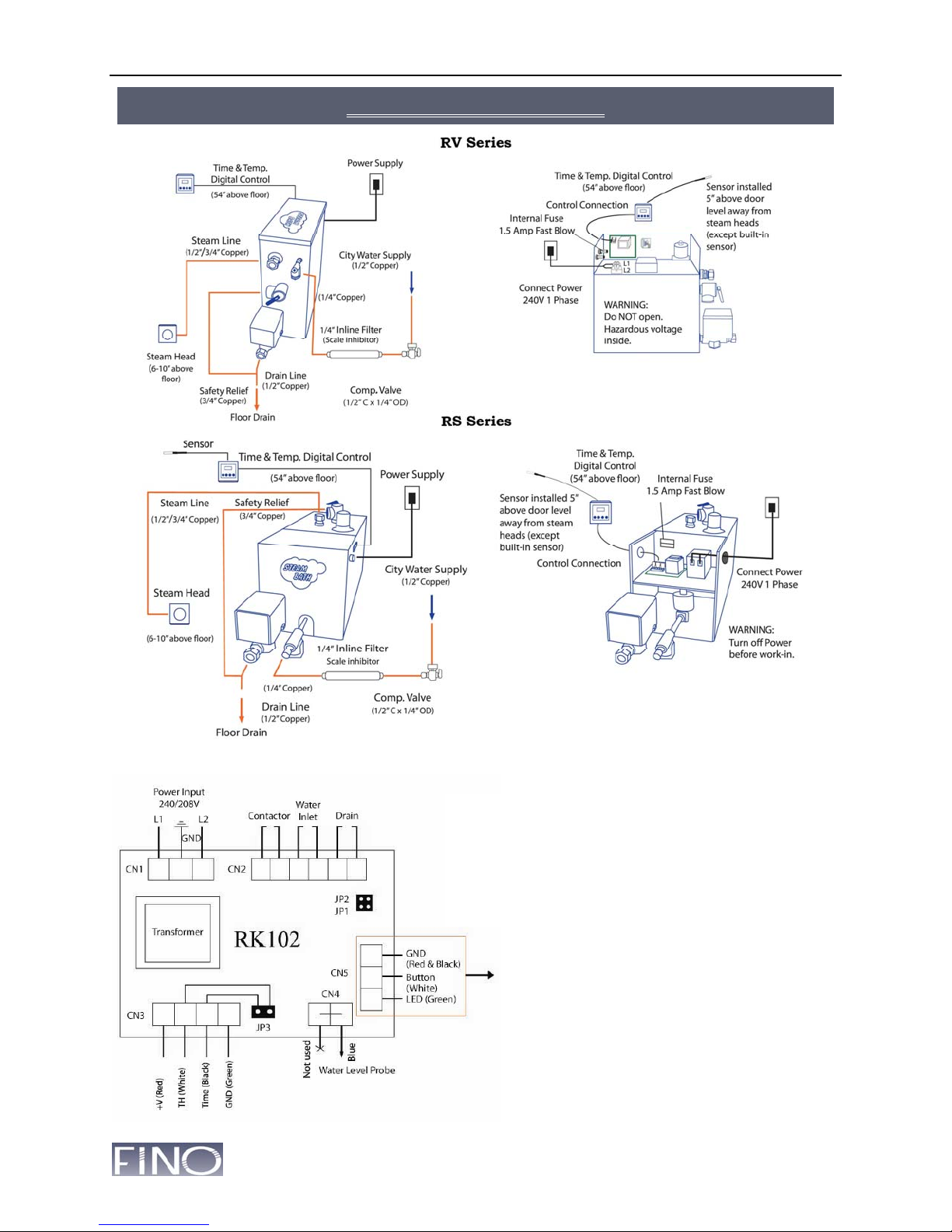
Wiring Diagram for Upgrading Computer Board
Jumpers:
JP1 Open: 90-min. safety feature active.
Close: Safety feature off.
JP2 Open: External timer with or without button.
Close: Only E-Touch button with 30-min. built-in
timer.
JP3: Open: Digital Timer.
Connectors:
CN1: 240V AC Input Power.
CN2: Output Connector.
CN3: Mechanical or digital timer
input.
CN4: Water Level Probe.
CN5: E-Touch Button Connector.
Not Used:
(Only with special instructions
from the manufacturer).
INSTALLATION
GUID
E

FINO®Installation, Operation & Maintenance Manual
4
Steam Room
Locate the legged surface under the unit, if you are using an existing completely tiled shower or
bathtub enclosure, make sure that it is enclosed to the ceiling.
Locating the Unit
Plan the location of your steam unit carefully. Place it for convenient installation and easy access.
A good location, when possible, is in a furnace room or storage room. Do not bury the unit in
walls or other inconvenient locations as it may require periodic maintenance. It may be placed up
to 50 ft. (15 m) from the steam room. A gravity drain will be necessary for all units requiring
drainage. Never locate the unit in an area that may be exposed to frost, or rain.
Positioning the Unit
Place this side (legged bottom) of the steam generator on a flat horizontally levelled surface. The
Front Access Panel should be easily accessible. This area contains the electrical components of
the unit. The Auto Flush units have a drain valve located at the front of the unit. This should
always face you, so that you have easy access to the valves. Place a levelling instrument on the
top of the unit, and be sure that it is horizontally levelled.
Installation in any other way will cause malfunction and burnout, voiding your warranty.
Step 1. Water Connection
Connect your water supply to your unit with 1/4" copper tubing, see Installation Guide. Install a
shut off manual valve between the unit and water line close to the unit. Before connecting water
line to the unit, flush the line into a pail or drain to free it of any plumbing residue. After it is
thoroughly flushed, attach the water line to the inlet line on the unit and open the water supply.
Check for any leaks.
If the water supply minerals are high, refer to “Filtration” section in the end of this manual.
Step 2. Steam Connection
A compression fitting is supplied at the steam outlet(s) labelled on the steam generator and a
½"/(¾”) copper pipe fits this fitting, see (Figure 1). Plumb from this point to the location of the
steam head or vice versa. Insulate the steam pipe to prevent temperature loss in output steam,
caused by heat exchange between pipe and surrounding air.
Drill a 3/4" hole into your steam room, 6"-12" above the floor or approximately 6" above the edge
of your bathtub. Locate the steam head in an area where you will easily avoid physical contact.
Connect the steam head to the pipe that you have brought through the hole into the steam room.
Direct the steam outlet slot in the steam head down toward the floor.
Do not install any valves or limiter between the unit and the steam head; Do not have
any low points in the steam line, that will allow condensation to sit in the pipe and
make noise, also build up pressure in the steam unit.
Step 3. Drain Connection
This is a gravity drain on all units with Auto Flush option. A compression fitting is supplied with
the unit and is to be installed on a ½" (¾” - SS15 up) copper pipe that slopes slightly downward
and away from the unit. It may run to an open floor drain or it can be plumbed into an existing
drain line.
GENERAL INSTALLATION INSTRUCTIONS

FINO®Installation, Operation & Maintenance Manual
5
Without i-cooling / i-cleaning system, the draining water is hot, avoid touching the
drain pipe that it may cause burns.
Step 4. Electrical Connection
Have a qualified electrician connect the unit. The power cable size and breaker size is to be
determined by an electrician. Use the specification sheet inside this manual to find the voltage
and wattage rating of your unit. All applicable electrical codes must be strictly adhered to.
Check your supply voltage to ensure it is compatible with the voltage listed on your unit’s label.
Electrical Power Connection
Install a Circuit Breaker in your Power Distribution Panel. Label that breaker as “Steam Gen”
Select Circuit Breaker size according to electrical codes. Run the power cable from Circuit
breaker to the unit and connect it to L1 and L2 (and L3 in 3 phase models). Fasten the ground
wire to the ground terminal inside steam unit.
Do not connect Neutral to the Ground Terminal, no neutral wire used in this electrical
connection
Use this steam unit as the factory set it up. Modify it only on recommendation from the
manufacturer. NEVER add valves or other controls to the steam line. To do so may cause
equipment failure or personal injury, and the warranty will be null and void.
For all models, please note the following steps:
When you need to shut down the power
1. Turn off the unit at the timer;
2. Wait for 15-30 seconds;
3. Shut down the main power supply.
Failure to do this may cause the microprocessor to malfunction.
1. Read all instructions in this guide prior to installing your steam generator.
2. Always ground the unit properly.
3. Make sure there are no restrictions in the steam line(s).
4. Always turn off the electrical supply and close the water line before doing any work on the
unit.
5. The wet surfaces of steam enclosures may be slippery. Use care when entering or leaving.
6. Use caution when near the steam head(s). They are very hot and may cause personal injury.
7. If you become overheated while in the steam bath, you should turn on the cold shower, open
the door and step out of the bath.
8. If you are pregnant, have heart problems, high blood pressure or physical symptoms other
than normal, consult with your doctor to determine if you should currently use a steam room.
9. Never use a steam bath after consuming alcohol or mind altering drugs.
10. Do not allow children to use a steam bath without adult supervision.
11. This unit is designed for steam baths only. If you wish to use it for other purposes, contact the
manufacturer to find out if it is suited for your application.
WARNING
SAFETY TIP
S

FINO®Installation, Operation & Maintenance Manual
6
Symptoms Possible cause Possible Solution
New unit does not produce
steam after it is connected
- Water is shut off
- Electrical Power is off
- Timer is not set
- Thermostat not set
- Unit not installed
correctly
- Not connected properly
- Ground terminal
connected with neutral
- Thermostat sensor loose
Connection
- Temperature setting
lower than room temp.
- Damage in shipping
- Turn on water supply
- Turn on power. Check circuit
breaker.
- Turn on timer
- Adjust thermostat to desired
temperature
- See Installation Guide &
Instructions on page 3 & 4.
- Check wiring
- Connect Ground Wire to the
Ground Terminal.
- Connect sensor to control panel
have room temp on display.
- Increase temperature set point
over the room temperature
- Contact manufacturer
Used unit not producing
steam
- No power
- Power is on, not working
- Water filter clogged
- Water keep running
- Drain valve stuck open
- Element burned out
- Contactor not engage
- Water level probe faulty
- Unit not produce enough
steam.
- Check & reset circuit
- Check & replace 1A/250V fuse
- Replace or clean filter
- Open & clean inlet valve
- Open & clean drain valve
- Replace element
- Check resistance on contactor
- Clean water level probe
- Calcium & mineral build up, send
back to refurbish.
Water comes from steam
head when * Power on
* Power off
- Water Level Probe faulty
- Heating element burnt
- Dirt on solenoid seat
- Clean water level probe
- Check power leakage on Ground
wire, replace heating element
- Clean solenoid valve, clean filter
Thumping noise when unit
is running.
- Water hammer on inlet
- Water condensing on
steam line
- Contactor buzzing noise
- Install water hammer suppressor
or flex in lieu of 1/4" copper tube.
- Find out low points, replace pipe
- Replace contactor
Unit does not drain;
Water runs through drain
valve continuously
- Drain stuck open
- Seal broken
- Drain plugged
- Manual drain optio
- Open valve & clean up
- Install rebuilt kit
- Open & clean valve
- Manually drain it after each use.
Unit heats but does not
produce sufficient steam
- Drain valve stuck open
and water leak through
- Heating element burnt
- Unit too small
- Clean valve
- Replace heating element
- Upgrade to larger unit
Steam room too hot, steam
dissipates
- Thermostat sensor not
properly placed
- Temperature setting
wrong
- Relocate sensor
- Check the temperature setting
Steam room not hot enough
- Thermostat sensor not
properly placed
- Steam line may too long
- Temperature set too low
- Improper sized unit
- Relocate sensor
- Insulate steam line
- Increase temperature set point
- Contact manufacturer
BASIC TROUBLE SHOOTING GUIDE

FINO®Installation, Operation & Maintenance Manual
7
RVRV
A. Installation
This controller is installed inside the steam room only, and it comes
with a built-in temperature sensor. The best location for the control is
close to your bench for easy access, also further away from steam
head. It is recommended to install the control pad from 36" up to the
maximum 48" height.
Note: The controller is provided with a 25 ft standard-length connector
cable. If you need to extend up to 50 ft, use 4-core wires (22 to 18 AWG).
B. Operation Programme for temperature setpoint and time setting.
1. Power Sign: Turns on or shut off the steam. When the control is in standby mode, the power
light stays on.
2. Temperature control: Controls the temperature set point in the steam room, which can set
from 10°C(50°F) to 85°C(185°F). To change the temperature setpoint, just touch the TEMP
sign for 3 seconds, while the control is on, then use the ▲(Up) or ▼(Down) to set it to desired
value (hold it to change faster), touch the ENTER to save it.
3. Time control: Controls the duration of steam operation, which can be set from 5 to 90
minutes in 1-minute increments. The unit will work until it times out. To change the time
setting, Touch the TIME sign for 3 seconds while the control is on, then use the ▲(Up) or ▼
(Down) to set it on desired time (hold it to change faster), touch the ENTER to save it.
4. Temperature/Time display: When the control is turned on, it displays the current
temperature in the steam room; By simply touch the temperature / time sign to switch the
display on temperature or time. On the time display, it will show the minutes counting down.
5. Celsius to Fahrenheit: To switch the display reading between Celsius and Fahrenheit, first,
turn off the control. Then touch the TEMP sign until the "F" or “C” turns on the display.
6. Lights (LEDs): There are 5 lights around the
display, each indicating a status:
- Power: is on as control is off in standby mode.
- TEMP: is on when there is a call for steam.
- TIME: is on when timer is still counting down.
- °c: is on when temperature is set for Celsius.
- °f: is on when temp. is set for Fahrenheit.
7. Default Setpoints: The control goes back to the
following default settings if the power is interrupted.
Temperature defaults: 47°C (117°F). Set range: (10 to 85°C)/(50 to 185°F).
Time default: 30 minutes. Set range: 5 to 90 minutes.
FiNO Control - Glass Touch
FINO®Installation, Operation & Maintenance Manual
8
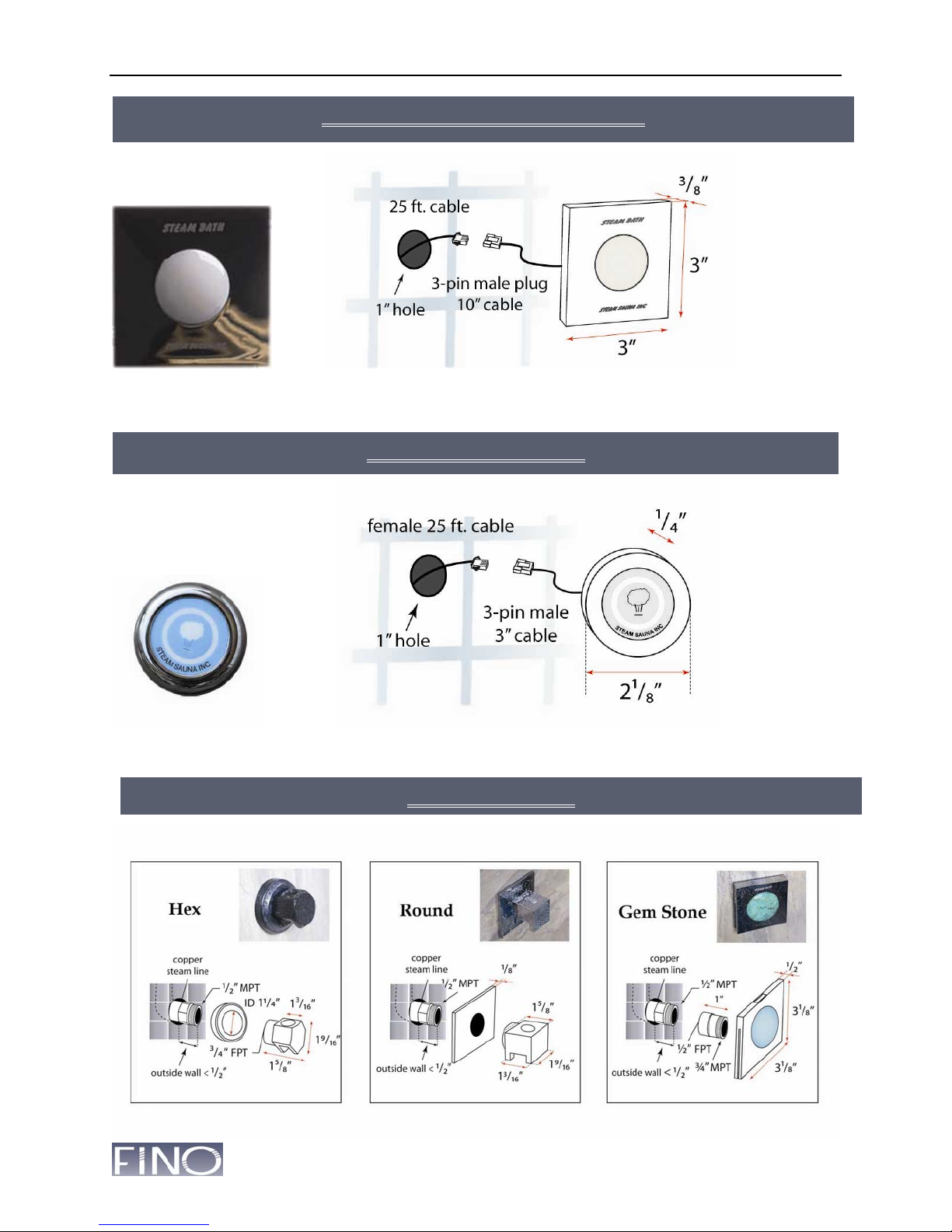
Touch to turn on and shut off steam with blue LED indicator light.
Touch to turn on and shut off steam with blue LED indicator light.
LED STONE TOUCH BUTTON
LED PUSH BUTTON
STEAM HEADS
FINO®Installation, Operation & Maintenance Manual
9
LCD
Filter System
Calcium and other mineral deposits are your steam generator’s worst
enemy. The factory installed a sediment filter on the incoming water supply
line is imperative. However, a secondary filtration system to reduce or
remove these components from the water prior to its entering the unit will
not only extend time between service calls, it will extend the life of your
unit. There are many filter options available as secondary filters. These will
reduce or even eliminate the mineral buildups within the tank.
Water Softener or Reverse Osmosis (R.O.) System
Either of these systems is ideally suited as a
secondary system. However, even if there is a
water softener set up on the house water other
than R.O. System, it is set up to accommodate
only the heating of water and not the boiling of
water. A secondary small softener dedicated to
the steam generator is generally recommended. It
will need to be set up slightly differently than the
house softener so that it strips all mineral
impurities from the water.
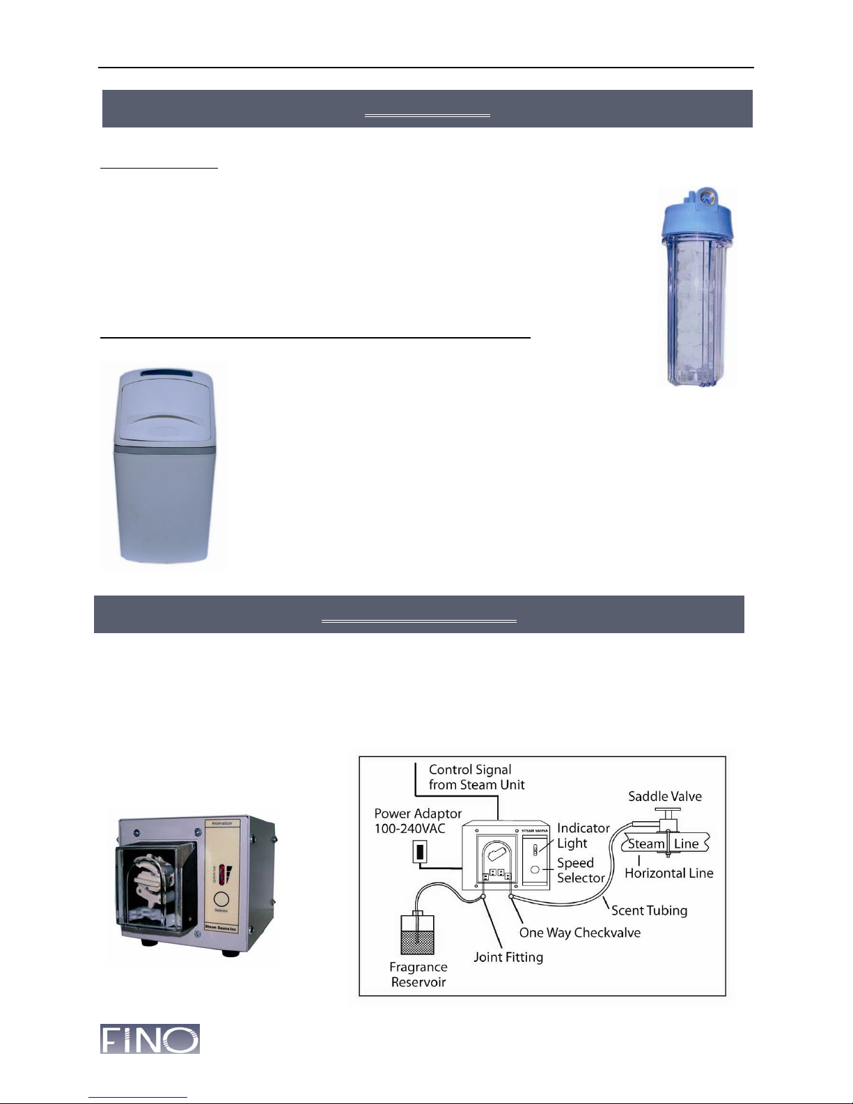
Scent dispenser pumps the fragrance (eucalyptus, wintergreen…) from the bottle into the steam
line. Install the scent pump beside the steam generator and connect its adopter to the power
source.
The scent tubing starts from the Fragrance Bottle and its black portion will be mounted on the
scent pump wheel. Then it ends to the saddle valve, which will tap into the steam line.
FILTRATION
Water
Scale
Inhibitor
Water Softene
r
Scent Dispenser
SCENT DISPENSER

FINO®Installation, Operation & Maintenance Manual
10
This manual suits for next models
15
Table of contents


