Fintek iCOOL User manual

Soluzioni per il benessere ed il risparmio
www.finteksrl.com
TECHNICAL MANUAL
ICOOL/IWARM
Be
f
ore installin
g
the air conditione
r
care
f
ull
y
read the instruction
s
iCOOL/iWARM
Pompe di Calore Monoblocco
ad Alta Efficienza

Index
Index
1. Main Features
2Certification( C )
2.
3. Overall Dimensions
4. Explosion view and parts list
5. Rated technical data
6
Elbl
6
.
E
nergy
l
a
b
e
l
7. Installation
8. Electric wiring
9. Description of software operation
10
Pi
10
.
P
recaut
i
on
11. Ordinary maintenance
12. Problem and solution

1.Main features
Double ducted machine is different with the normal split type air conditioner, and there is no outdoor
unit, and installed with high wall. It is a special solution for commercial and residential buildings.
Th t i
d t t li i t it b h d ff t l k t th b ildi l
Th
e
t
w
i
n-
d
uc
t
sys
t
em e
li
m
i
na
t
es secur
it
y
b
reac
h
es an
d
o
ff
ers a grea
t
l
oo
k
t
o
th
e
b
u
ildi
ng, as on
l
y
2x200mm holes are required.
The benefits of no outdoor unit are: no sleeve, no louvers and no rust, ensuring low cost installation
and maintenance. The heat pump provides low operating costs when in heating mode.
• R410a gas, friendly refrigerant with high efficiency ozone.
•
Auto water evaporation in cooling and heating mode
Auto
water
evaporation
in
cooling
and
heating
mode
• Intelligent control technology.
• High-efficiency cooling and heating performance.
•Silent operation
• Full function LCD remote control
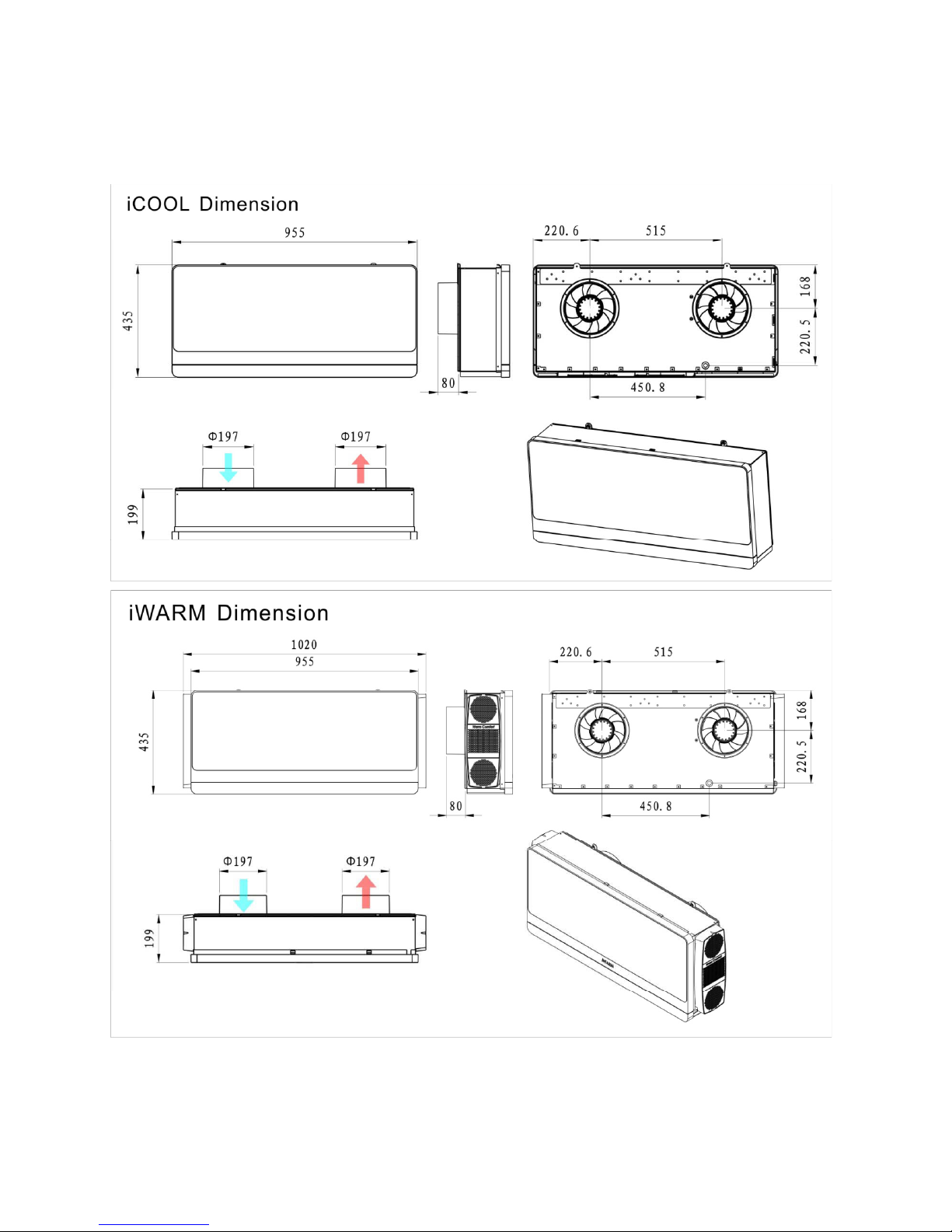
3. Overall Dimensions
Note : The external pipes are same, Ø197mm .

4. Explosion view and parts list
4.1 iCOOL Explosion view

iCOOL Parts list
No. in Explosive
View ),17(. code BOM English Name Qty
1 R133140024 Compressor and accessory 1
2 R122050360 Condenser assy. 1
3 R122060135 Capillary assy. 1
4 R122010207 Evaporator assy. 1
5 R122120281 4-way valve assy. 1
6 R131040178 Indoor motor 1
7 R131040175 Anticlockwise condenser fan 1
Cf
8 R131040176
C
lockwise condenser
f
an 1
9R131060068 Step motor (panel) 1
10 R131060066 Step motor (plap) 1
11 R131010509 Main PCB 1
12 R131160054 Compressor capacitor 1
13 R127030254 Compressor capitor holder
14
R131030006
3
way terminal block
1
14
R131030006
3
-
way
terminal
block
1
15 128060209 Wire protection ring 1
16 R131130003 Condenser fan capacitor 2
17 R139010035 Power plug protection ring 1
18 R132040139 Power plug 1
19 R128030549 PMMA 1
20
R128030543
Front panel
1
20
R128030543
Front
panel
1
21 R128030545 Front frame 1
22 R128030555 Outlet frame 1
23 R128030557 Flap1 1
24 R128030572 Flap2 1
25 R138140752 Insulation material for flap1 1
26 R128030547 Ste
p
motor box 1
p
27 R128030550 Linkage 1
28 R128030551 Connecting rod 1
29 R128030552 Coupler 1
30 R128030554 Short pin 2
31 R128030553 Long pin 5
32 R128030548 Air filter 1
33 R128030561 Outside grille 1
34 R128030286 Axis sleeve 2
35 R128050021 Tangential fan 1
36 R139050004 Axletree seat 1
37 R128060423 Bottom EPP 1

38 R128060422 Upper EPP 1
39 R128060424 Condenser cover EPP 1
40 R128060427 Front cover EPP 1
41 R128060426 Evaporator cover EPP 1
42 R128060425 Water cover EPP 1
43 R140140071 Bottom metal assy. 1
44 R127020799 Compressor installation plate 1
45 R127041004 Right metal plate 1
46 R127030288 Electrical box 1
47 R127020823 Support plate 1
48 R127080061 Wall bracket assy. 1
49
R127020801
Back metal plate
1
49
R127020801
Back
metal
plate
1
50 R127020803 Top metal plate 1
51 R127041005 Left metal palte 1
52 R127020796 Evaporator motor support 1
53 R127020798 Indoor motor holder 2
54 R138140753 Insulation material for flap2 1
55 R138140699 Bottom plate sponge 1
56 R138140700 Compressor bottom sponge 1
57 R138140725 Front cover EPP sponge 1
58 R138140716 Electrical box top sponge 1
59 R138140717 Electrical box side sponge1 1
60 R138140718 Electrical box side sponge2 1
61 R138140724 Right metal plate sponge 1
62 R138140696 Condenser insulation s
p
on
g
e1
pg
63 R138140698 Evaporator insulation sponge 1
64 R138140729 Wall bracket insulation sponge 1
65 R138140701 Back metal plate sponge 1
66 R138140573 Capacitor sponge 1
67 R138140723 Condenser fan insulation sponge 1
68 R138140720 Outlet frame sponge1 1
Of
69 R138140721
O
utlet
f
rame sponge2 1
70 R138140705 Top metal plate sponge 1
71 R138140706 Condenser cover EPP sponge 1
72 R138140704 Left metal palte sponge 1
73 R138140726 Front cover insulation sponge 1
74 R138140727 EPP insulation sponge 1
75 R139010076 Water plug 1
76 R128070006 Drainage pipe 1
77 R131020097 LED display 1
78 R131170067 Remote control 1
79 R128040261 Remote control seat 1
80 R131100001 Battery 2

4.2 iWARM Explosion view

No. in Explosive
View ),17(. code BOM English Name Qty
iWARM Parts list
1 R128030549 PMMA 1
2 R128030543 Front panel 1
3 R128030554 Short pin 1
4 R128030552 Coupler 2
5 R128030548 Air filter 1
6 R128030553 Long pin 5
7 R131020097 LED display 1
8 R128030545 Front frame 1
9 R128030547 Step motor box 1
10 R128030550 Linkage 1
11 R128030551 Connectin
g
rod 1
g
12 R131060068 Step motor (panel) 1
13 R128030557 Flap1 1
14 R128030572 Flap2 1
15 R128030555 Outlet frame 1
16 R131060066 Step motor (plap) 2
17 R127041116 Right metal plate 1
18 R131040178 Indoor motor 1
19 R127020796 Evaporator motor support 1
20 R127020798 Indoor motor holder 2
21 R128060423 Bottom EPP 1
22
R128050021
Tangential fan
1
22
R128050021
Tangential
fan
1
23 R122010207 Evaporator assy. 1
24 R128060422 Upper EPP 1
25 R128060427 Front cover EPP 1
26 R127020823 Support plate 1
27 R140140071 Bottom metal assy. 1
28 R127020799 Compressor installation plate 1
29 R128060425 Water cover EPP 1
30 R128060426 Evaporator cover EPP 1

31 R122060135 Capillary assy. 1
32 R133140024 Compressor and accessory 1
33 R122120281 4-way valve assy. 1
34
R122050360
Condenser assy
1
34
R122050360
Condenser
assy
.
1
35 R127030288 Electrical box 1
36 R131160054 Compressor capacitor 1
37 R127030254 Compressor capitor holder 1
38 R131030006 3-way terminal block 1
39 R131130003 Condenser fan capacitor 2
40 R131010509 Main PCB 1
41 R132040139 Power plug 1
42 R127041117 Left metal palte 1
43 R128060424 Condenser cover EPP 1
44 R127020803 Top metal plate 1
4
5
R127
0
2
080
1B
ac
k m
eta
l
p
l
ate
1
5
0 080
ac eta p ate
46 R131040175 Anticlockwise condenser fan 1
47 R131040176 Clockwise condenser fan 1
48 R138140701 Back metal plate sponge 1
49 R128030561 Outside grille 2
50 R128070006 Drainage pipe 1
51 R131170148 Remote control 1
52 R128040261 Remote control seat 1
53 R131100001 Battery 2
54 R127041118 PTC heater cover 2
55 R122230031 PTC heater assy. 2
56 R131050102 12VDC fan blade 4
57 R128040450 PTC fixing plastic box 2
58 R128020543 PTC air filter 4
59 R128020519 PTC inlet grille 4
60 R127090128 PTC protection net 2
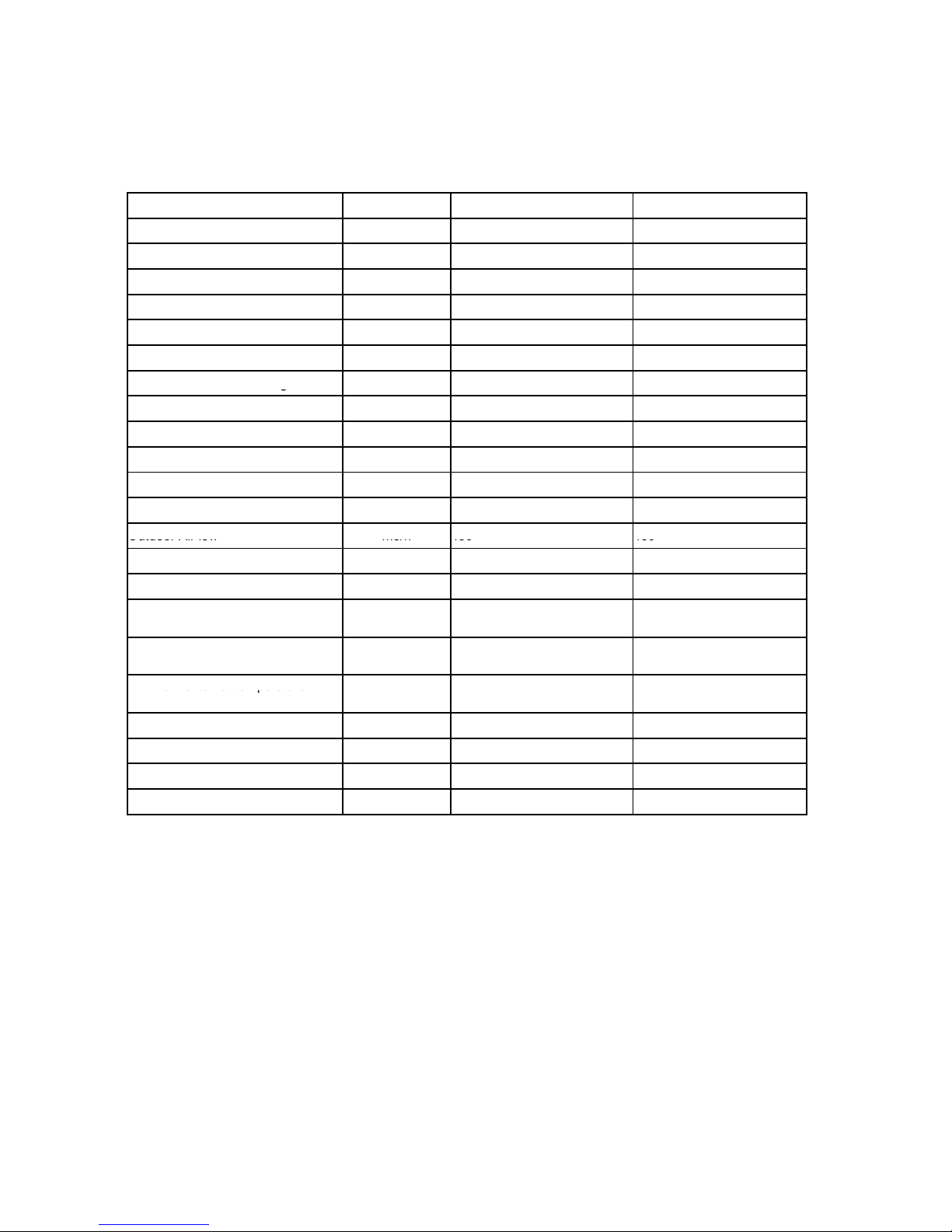
5.Rated technical data
Descriptions Unit ICOOL 2.3 IWARM 2.3
Cooling capacity W (Btu/h) 2360 (8050) 2360 (8050)
Heating capacity W (Btu/h) 2()2()
Rated voltage V 230 230
Frequency Hz 50 50
Electrical heater W (Btu/h) ------- 1600 (5500)
Absorbed power in cooling W 904 904
Absorbed current in coolin
g
A 3.9 3.9
g
Absorbed power in heating W
Absorbed current in heating A 4
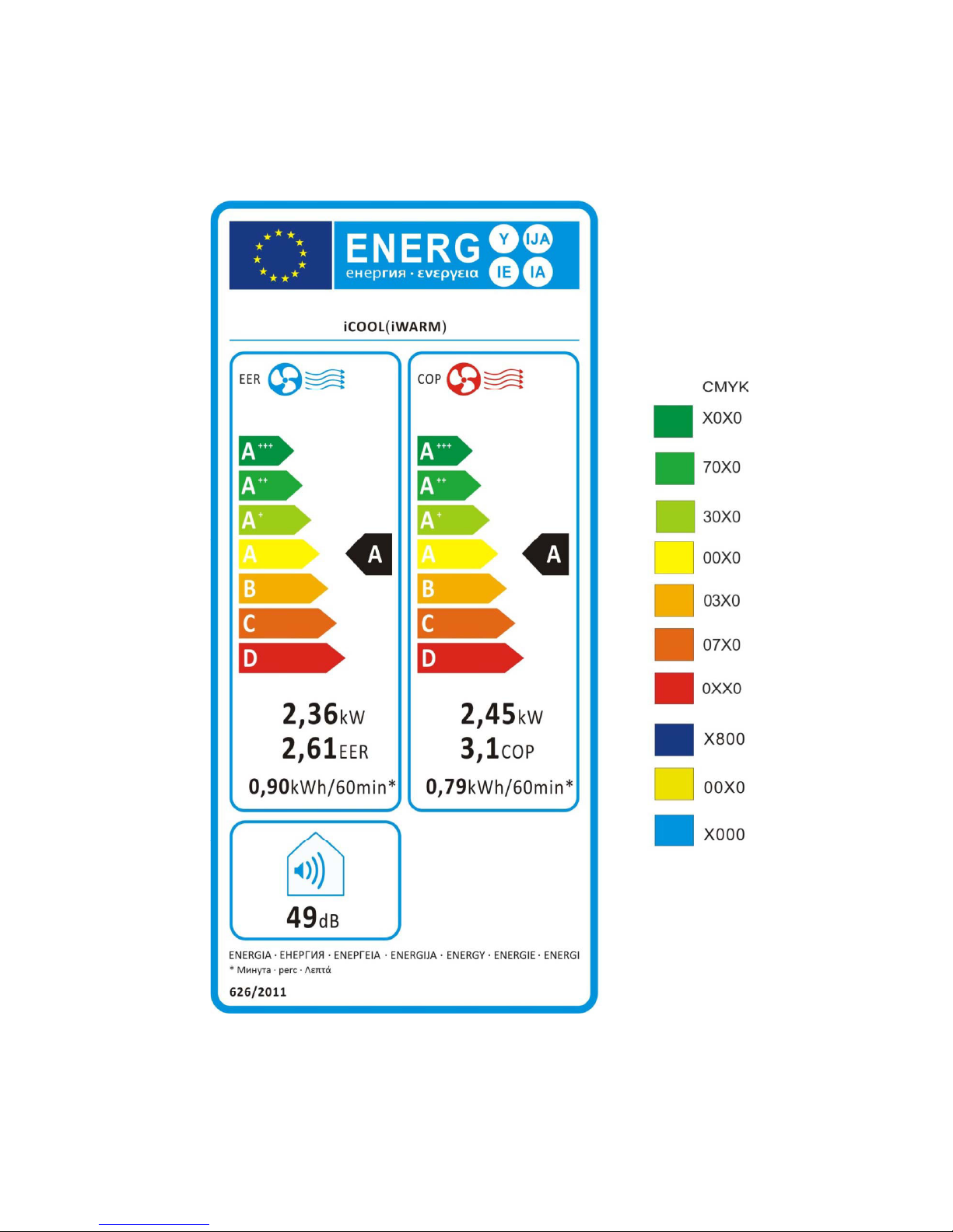
EER label ( Cooling Mode ) ABCDEFG AA
COP lable ( Heating Mode ) ABCDEFG A A
Indoor Air low m3/h 350 350
Outdoor Air low
m3/h
450
450
Outdoor
Air
low
m3/h
450
450
Noise lever ( SPL ) dB(A) 49 49
Dehumidification capacity L/24h 12.5 12.5
Optional temperature (remote
control) ć18-30 18-30
Maximum external temperature *** eC 43 43
Minimum external temperature HP
e
C
5
5
Minimum
external
temperature
HP
****
e
C
-
5
-
5
Fuse (T3,15L) V 250 250
Refrigerant / R410a g 640 640
Dimension H/W/D cm 43/95.5/19.5 43/102/19.5
Net Weight Kg 40 42
**The above data could be changed in order to improve the performance.
*** The machine can work at T3 condition , with max out door temperature 52
eC but the cooling performance will be reduced .
**** The machine can work at -15 eC , but the Heating performance will be
reduced .
7. Installation


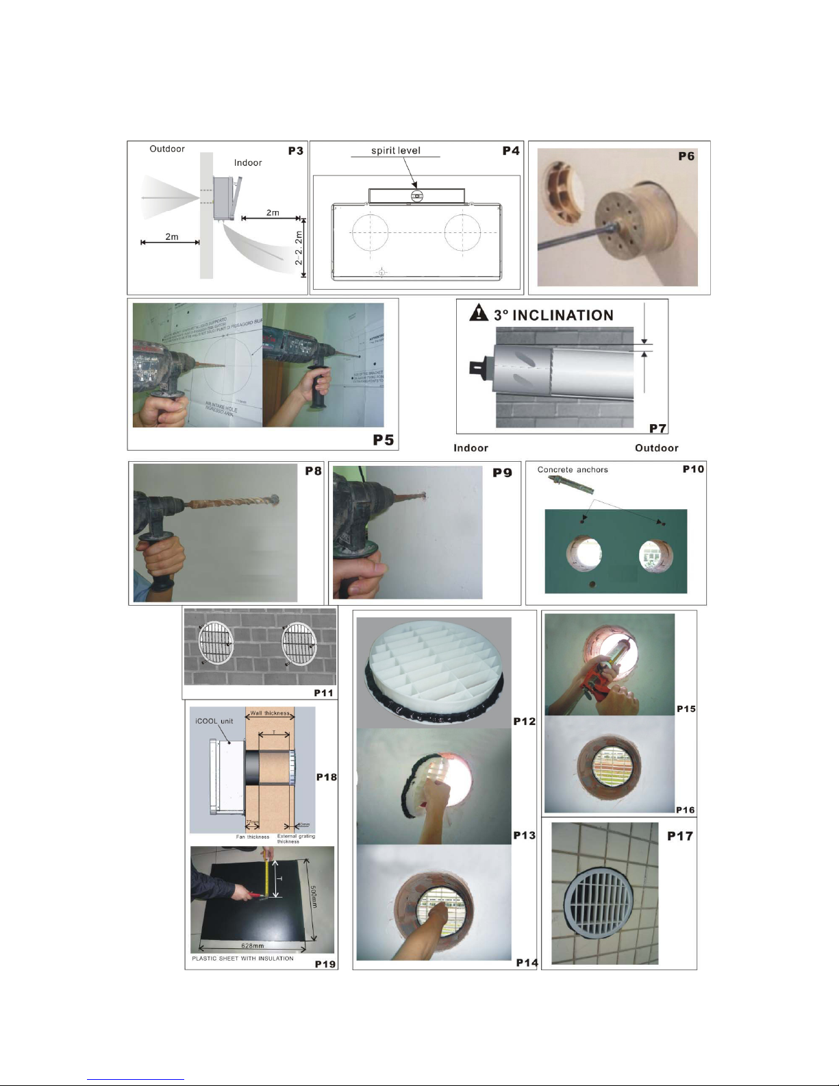
7.1 Positioning the air conditioner (P3)
To maintain the best performance from your air conditioner, prevent breakdowns or hazards, you
must position it correctly.Please follow the guidelines and instruction below in full, as failure to do so
could cause potential installation problems.
The air conditioner must be installed on an exterior wall that has access to the out side with a
minimum of 2 meters clearance to the outside.(See image P3)
The air conditioner must be fitted leaving room all around as illustrated in the paper template.
The wall on which the air conditioner is installed must be sturdy and able to withstand the weight for
the air conditioner.
After determining the best place for installation as described above. Please check to ensure that the
wall can be drilled in the chosen area without interferin
g
with other structures or installations
(
beams
,
7.2 Paper template (P4)
g(,
piers, pipes, wires, etc.).
Please also ensure that there are no obstacles on the outside of the wall, which may obstruct air
circulation through the drilled holes, for example:(plants and their leaves, slats or panelling, drain
pipes, overflows and gratings,etc.). Any obstruction could interfere with the correct performances of
the air conditioner.
Fasten the template to the wall once the following guidelines have been thoroughly checked.
• Do not drill any holes until you are completely confident that there are no obstacles in the area you
wish to drill and there are no obstructions, which could be hidden by the construction of the wall, for
example: electrical wiring, water&gas pipes or supporting lintels or beams.
• Ensure that a spirit level is used, as the air conditioner must be level.
• Follow the installation instructions in full.
•Fasten the template to the wall taking care to check the distance from the floor or ceiling.
•Use a pilot drill to mark the centre of each core hole to be drilled.(See image P5)
7.3 Drilling the wall(P6,P7,P8)
Please note:If you are drilling the hole above ground floor level, please ensure that an area has been
secured and while the holes are drilled the outside area is supervised until drilling has been
secured
and
while
the
holes
are
drilled
the
outside
area
is
supervised
,
until
drilling
has
been
completed.
Intake and outlet holes
• This operation should be carried out using the proper tools ( diamond tip or core borers drills with
high twisting torque and adjustable rotation speed).
•Find the holes center drilled before, use a core boring head having a diameter of 200mm to drill the
two holes for intake and outlet the air.
Thi ti h ld b i d t i th t l (di d ti b d ill ith hi h
•
Thi
s opera
ti
on s
h
ou
ld
b
e carr
i
e
d
ou
t
us
i
ng
th
e proper
t
oo
l
s
(di
amon
d
ti
p or core
b
orers
d
r
ill
s w
ith
hi
g
h
twisting torque and adjustable rotation speed).
Note: It is recommended that the holes must have a slightly downward inclination of 3-5 degree to
prevent any backflow of water from the pipes.

Drainage hole (P8)
This air conditioner has a system to drain the condensate moisture automatically. Please read
carefully the following instruction.
Drill a hole through the wall measuring 30mm in diameter in the position shown in the paper template,
Drill
a
hole
through
the
wall
measuring
30mm
in
diameter
in
the
position
shown
in
the
paper
template,
marked the center before. Drainage occurs by gravity. For this reason, it is essential for the drain line
to have a minimum downward inclination at least 3 degrees throughout its length. With this solution,
you can drain the condensate moisture to a suitable place to do not cause any problems to your
neighbours.
This drainage method is more common use, and the discharge pipe goes outside where there is no
problem to connect or to discharge it, this solution is OK for hot country and normal cold temperature
outside.
Wllb kthl (P9)
W
a
ll
b
rac
k
e
t
h
o
l
es
(P9)
Drill the holes for anchoring the unit to the wall using preferably the 2 holes with 10mm diameter
showed in black on the paper template. As the unit is installed on high wall, it is recommended that the
bolts should be fixed very well.
7.4 Fastening the anchors (P10)
Insert the concrete anchors into the holes for the unit and tighten them inside the wall
Insert
the
concrete
anchors
into
the
holes
for
the
unit
,
and
tighten
them
inside
the
wall
.
The anchor bolts provided require 10mm holes; the wall should be inspected to determine if provided
bolts are useful or if it is necessary to use a different anchorage. The manufacture is not liable in case
of underestimation of the structural consistency of the anchorage made at the time of installation.
7.5 Fitting the gratings
After drilling the holes, the plastic gratings supplied with air conditioner need to be fitted on the wall.
1.When gratings is easy accessibility, you could fix the gratings from outside, it is recommended to
fasten it to the wall with wall plugs and screws with a diameter of 6mm, and keep the fins in vertical
position. (See image P11 )
2. When the air conditioner is installed in the high space, and impossible to reach the gratings from
outdoor side, you could fix the gratings from inside.
Put the silicon gel around of the soft grating, like Fig17.Then fold the outer grating in half, insert your
arm inside the hole with the grating. Let the grating unfold and pull the grating toward you. With a little
i d i l i h 2 i ill fi h d f h h l (P12 13 14)
pat
i
ence an
d
man
i
pu
l
at
i
on, t
h
e
2
grat
i
ngs w
ill
fi
t t
h
e en
d
o
f
t
h
e
h
o
l
es.
(P12
,
13
,
14)
After fixing the outside grating,we could inject more gel inside the space between the grating and wall.
(See P15,16)
The black silicon gel is just for reference, we could use white or transparent color gel to fix the outdoor
grille.(P17)
The above installation solution is just for solid wall.

7.6 Fixing plastic sheet and insulation
After fixing the outside grating,insert the plastic sheet with insulation supplied with the conditioner
into the holes.The sheets must be 107mm shorter than the thickness of the wall.(See P18)
Use an ordinary cutter for the operation. (See P19)
Roll the sheet and insert it into the hole, paying attention to the splicing line, which must always
face up wards.(See P20)
7.7 Connecting drainage pipe
Connect the drain pipe(from rubber terminal) to the air conditioner (back side) after unplugged the
black rubber cu
p
(
see P21
)
.
p( )
With this solution, you can drain the condensate moisture to a suitable place to do not cause any
problems to your neighbours.
1. When the machine is installed in normal climate or hot area, we can connect the drainage pipe
to outside, with a proper place. (See P22)
2. When the machine is installed in very cold area, the water in drainage pipe is frozen easily in
winter, we could connect the drainage pipe inside the wall, and connect with a proper
place.(See P23)
7.8 Fitting the air conditioner on anchors
After checking again that the fastening anchors are securely fastened to the wall, and that any
necessary preparations for electric connection and condensate drainage have been made, fasten
the air conditioner to its supporting anchors.(See P24)
Lift it up by holding the sides at the bottom, slightly insert the outside fan rings into the two big
holes on the wall.
(
See P25
)
The air conditioner can now be
p
ushed firml
y
a
g
ainst the wall
,
then lift
() p yg
,
the unit and make sure the anchors and unit match well. (See P26)
Inspect carefully the installation to make sure that the insulating back panel must fit firmly against
the wall and there are no fissures at the back of the air conditioner.
Fixing two nuts with top of the machine, to make sure the unit is installed well. (See P27,28)
Note:
1. The appliance shall not be installed the laundry.
2. The appliance must be positioned so that the plug is accessible.
3. The appliance shall be installed in accordance with national wiring regulations.
7.9 Power cord connection
For every unit, there would be a power cord on the left side(P28).Connect the plug with the socket,
and operate the unit.

8. ICOOL/IWARM Electric wiring

9.1 Main technical index
PCB h ld t th f ll i i t
9. Description of software operation
PCB
s
h
ou
ld
mee
t
th
e
f
o
ll
ow
i
ng requ
i
remen
t
s:
• Measured from the receiverˈreceiving distance of remote control should 8mˈreceiving
angle60econe angle˗
• Discrepancy of temperature controlf1ć˗
• Discrepancy of time control5min/24h˗
• Discrepancy of indoor PG fan speed˖f10rpm˗
Rd l
AC230
f
20%
0H
•
R
ate
d
power supp
l
y˖
AC230
f
20%
ˈ5
0H
z˗
• PCB should conform to RoHS.
9.2 Definition
•RT˖room temperature.
•IPT˖indoor coil temperature.
•ST˖setting temperatureˈrange 1830ć
•OPT˖outdoor coil temperature.
• NTC data˖R25=5.0Kȍf1% B25/50=3470f1%
9.3 Mode introduction
931Automode
9
.
3
.
1
Auto
mode
After running the unit by ON/OFF key or choose the auto running mode by remote control, it will fix its
running mode by judging room temperature (see below table):
Indoor temp. Indoor temp.20
ć
20
ć˘
indoor
˘
25
ć
indoor25
ć
Running mode heating fan cooling
St d d fi d
20
ć
22
ć
25
ć
St
an
d
ar
d
fi
xe
d
setting temperature
20
ć
22
ć
25
ć
Note:
1. When Auto mode is selected, unit would check room temperature first and work with fixed mode as
above accordingly. Every 6 minutes, unit would check room temperature again, running mode would
be changed according with update room temperature.
2
If working mode is changed by remote control unit has 3 minutes delay protection for compressor
2
.
If
working
mode
is
changed
by
remote
control
,
unit
has
3
minutes
delay
protection
for
compressor
.
3. Fan speed selection: For Dry mode, fan speed is fixed with low speed. For Cooling, Heating and Fan
mode, fan would work with set speed.
4. Unit has protection function, including 3 minutes delay function, Anti-cold function before heating,
Over heating protection during heating function, Anti-frozen during cooling mode, E1,E2,E3,E4
protection.
This manual suits for next models
1
Table of contents
Other Fintek Air Conditioner manuals


Popular Air Conditioner manuals by other brands


Samsung
Samsung AR18NSWSPWKXCV Service manual

Kenmore
Kenmore 405.84086 Use & care manual

Mitsubishi Electric
Mitsubishi Electric MFZ-KA25VA Service manual

Sharp
Sharp AU-1802Y Operation manual

Mitsubishi Electric
Mitsubishi Electric City Multi Series Technical & service manual

Haier
Haier HSU-10VNJ17 Operation manual