Fintek WINDY 3 HP User manual
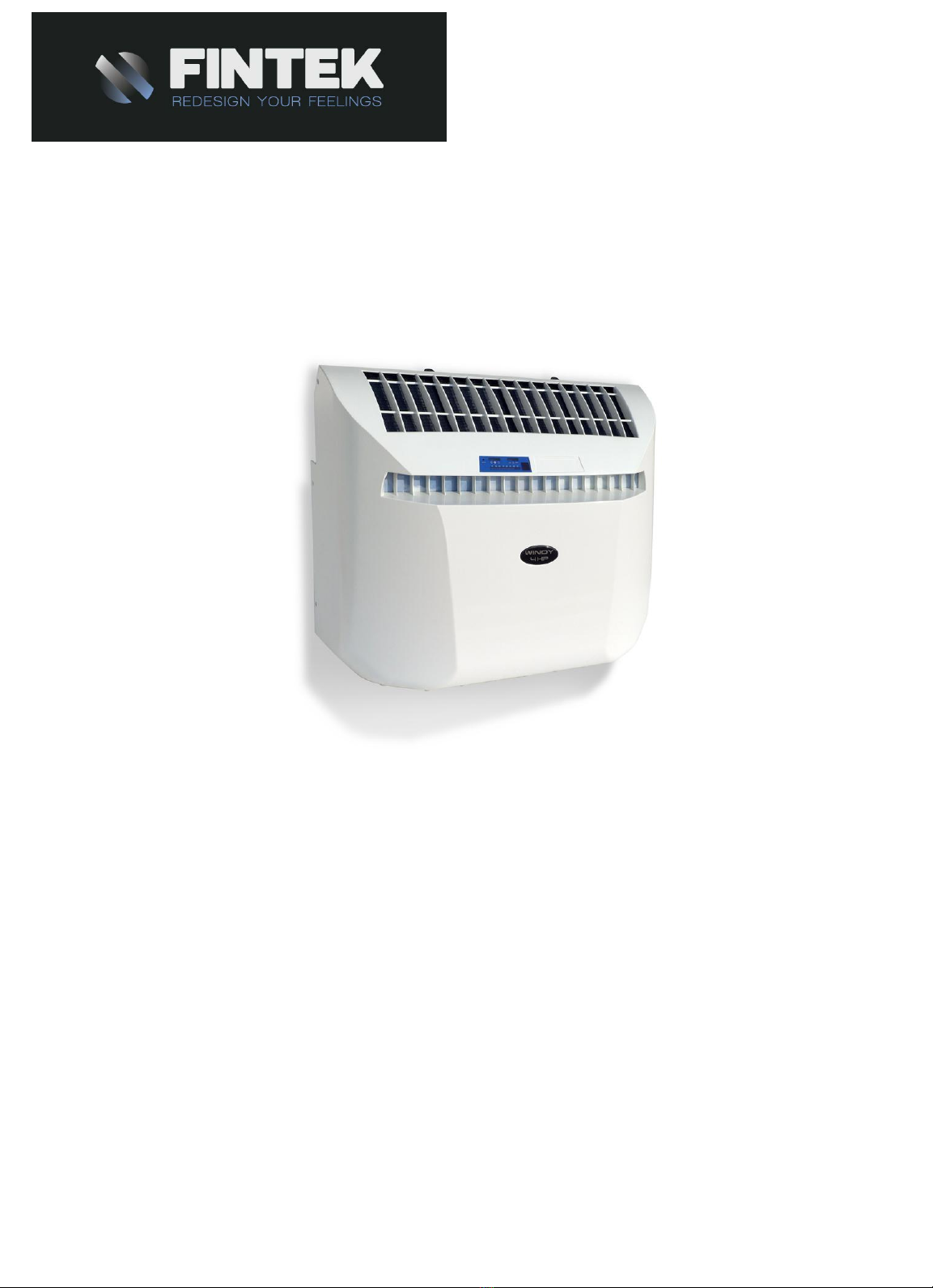
WINDY AIR CONDITIONING
3HP - 4 HP -5 HP - 4 HP I - 5 HP I
INSTRUCTION MANUAL
910.100.179GB REV08

5 di 24
MAIN COMPONENTS WINDY 3 – 3 HP – WINDY 4 – 4HP ....................... pag.6
MAIN COMPONENTS WINDY 5 – 5 HP – 5 INVERTER .......................... pag.7
CAUTION ............................................................................................. pag. 8
INSTA ATION .................................................................................. pag.8
HOW TO INSTA IT COMPONENT ...................................................... pag.9
E ECTRICA CONNECTION.................................................................. pag.11
HOW TO OPERATE IT CONTRO PANE , DESCRIPTION....................... pag.11
DISP AY PANE ................................................................................... pag.11
REMOTE CONTRO DESCRIPTION....................................................... pag.12
NIGHT OPERATION .............................................................................. pag.13
COO ING / HEATING ............................................................................ pag.13
VENTI ATION ........................................................................................ pag.13
DEHUMIDIFICATION ............................................................................... pag.13
AUTO .................................................................................................... pag.13
AUTOMATIC ........................................................................................ pag.14
TIMER-ON DE AYED SWITCHING ON..................................................... pag.14
TIMER-OFF DE AYED SWITCHING OFF.................................................. pag.14
Defrosting................................................................................................ pag.14
Heating efficiency.................................................................................... pag.14
Operating limits and warning signals...................................................... pag.14
MAINTENANCE AND CARE.................................................................... pag.15
Trasport ................................................................................................. pag.15
Standard maintenance ............................................................................ pag.15
How to clean the air filter ........................................................................ pag.15
How to clean the cover............................................................................. pag.16
At the end of the season......................................................................... pag.16
TROUB E SHOOTING............................................................................. pag.16
CONDENSE WATER TAP KIT (OPTIONA )............................................... pag.17
TECHNICA DATA .................................................................................... pag.18
WIRING DIAGRAM .................................................................................. pag.19
WIRING DIAGRAM WINDY INVERTER....................................................... pag.20

6 di 24
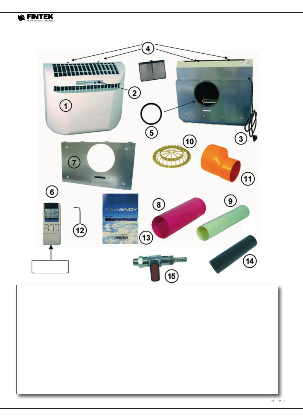
MAIN COMPONENTS WINDY 3 – 3 HP – WINDY 4 – 4HP
MAIN COMPONENTS WINDY 3 – 3 HP – WINDY 4 – 4HP
1 . Air conditioner
2 . Control panel
3 . Electrical cable with plug
4 . Air filters
5. Back plate sponge O-ring seal
6 . Remote control
7 . Counter-frame
8 . External air intake pipe open Ø 150
9 . nternal air delivery pipe Ø 100
10. External grid
11 . Allen key for water tank tap
12 . nstallation manual
13 . Tap (option)
MAIN COMPONENTS
MAIN COMPONENTS
Batteries not
included
7 di 24
MMAAIINN
CCOOMMPPOONNEENNTTSS
WWIINNDDYY
55
––
55
HHPP
––
1 . Air conditioner
2 . Control panel
3 . Electrical cable with plug
4 . Air filters
5. Back plate sponge O-ring seal
6 . Remote control
7 . Counter-frame
8 . External air intake pipe open Ø 150
9 . nternal air delivery pipe Ø 100
10. External grid
11. Connection 100 -140
12. Allen key for water tank tap
13. nstallation manual
14. Sponge
15. Tap (option)
MAIN COMPONENTS
MAIN COMPONENTS
Batteries not
included

8 di 24
CAUTION
This air-conditioner was designed for internal use.
- The air-conditioner must be installed vertically on
an even surface and on perfectly vertical walls.
(please refer to paragraph ‘ nstallation’) (Pag. 10)
- The connection to the mains must be carried out
according to the existing installation rules (please
refer to paragraph ‘Electrical Connection’) (Pag. 14).
- Make sure that curtains and/or other objects do not
obstruct the air intake filter and the internal air
delivery pipe, and that plants, shutters and blinds
do dot obstruct the external air intake.
- The air-conditioner must never be installed in
laundry rooms or in particularly damp rooms such
as greenhouses etc
- The air-conditioner must never be installed in
rooms containing explosive gases and/or
vapours or dangerous materials, or in rooms
where other machines generate high heat.
- Never place any object on top of the air-
conditioner
- Do not introduce any object in the internal and
external air outlets; this might cause injuries to
people and damage the machine.
- Do not switch on or off the air-conditioner by
plugging in or out the electrical plug into and from
the socket. This procedure, if frequently repeated,
might damage the cable, the plug or the socket,
which, in turn, might cause injuries to people. Use
always and only the remote control, and use the
protection switch device. (Please refer to ‘Electrical
connection’)
- Do not damage, pull, crush or fix with nails the
supply cable. When the supply cable is damaged,
please call the technical department.
- f you are not going to use the air-conditioner for
a long time, deactivate the protection switch device
and remove the plug from the socket.
- When installing the air-conditioner, mind that cool
air is not directly routed towards people.
- Do not install an oven where it may be directly
subject to the airflow from the air-conditioner, as
this may cause imperfect combustion
- We recommend ventilating periodically the room
where the air-conditioner is installed, especially if
the room is very crowded or if there are gas ovens
or smell sources.
- Do not use the air-conditioner for a long time with
open doors or windows; you will thus avoid
generating an excessive amount of condensate
water, in addition to achieving an energy saving.
- The ecologic cooling gas (R410A) used in the air-
conditioner has null oxygen depauperization
properties (ODP=0). n spite of that, the air-
conditioner must be disposed of in the proper
disposal centres.
INSTA ATION
How to install it
To successfully install it and to have optimal
operating performances, follow carefully the
instructions contained in this manual.
Non-compliance with installation procedures may
cause the air-conditioner not to work properly and
relieves Fimer Air Conditioning from any warranty
duty and from any responsibility in case of
damages to people, animals or objects.
Where to install it
The air-conditioner must be installed according to
the specifications detailed below:
- Only install the air-conditioner on an outer wal
- The wall must be sufficiently strong to support the
weight of the unit and to guarantee an adequate
fixing.
- Leave enough room around the unit for
maintenance interventions (as indicated in the
picture 1).
- f you install it in a low position: minimum distance
from the floor: 300 mm.
f you install it in a high position: minimum distance
from the ceiling: 150 mm
- There must never be obstacles (such as plants,
flower-pots, thick gratings etc.) to the free
circulation of the air from the coaxial pipe and from
the air delivery pipe (please refer to the
picture 2), as this might
jeopardize the proper operation
of the air-conditioner.
- Please make sure that, where
you intend to drill the hole for
the coaxial pipe, there are
neither electric cables, water
pipes, installations etc., which
might be damaged, nor pillars
and beams, as the drilling of
the hole would become
extremely difficult.
Fig. 1
Fig. 2
This manual suits for next models
4
Table of contents
Other Fintek Air Conditioner manuals


Popular Air Conditioner manuals by other brands

Fujitsu
Fujitsu ASYG 09 LLCA installation manual

York
York HVHC 07-12DS Installation & owner's manual

Carrier
Carrier Fan Coil 42B Installation, operation and maintenance manual

intensity
intensity IDUFCI60KC-3 installation manual

Frigidaire
Frigidaire FAC064K7A2 Factory parts catalog

Sanyo
Sanyo KS2432 instruction manual


Mitsubishi Electric
Mitsubishi Electric PUHZ-RP50VHA4 Service manual

Panasonic
Panasonic CS-S18HKQ Service manual

Panasonic
Panasonic CS-E15NKE3 operating instructions

Gree
Gree GWH18TC-K3DNA1B/I Service manual

Friedrich
Friedrich ZoneAire Compact P08SA owner's manual

Daikin
Daikin R32 Split Series installation manual