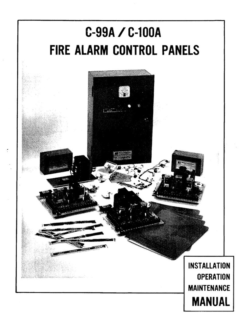
Fire Burglary Instruments XL 1219 Installation manual

P
w
“r.I
XL1219
Programming Instructions
’
--=-.
:;
Fire Bur~lmry hstruhentsi Inc.. ;--Lf’a.
L -
50 Engineers Road, Hauppauge, New York 11788 . ‘(800) 645-5430 ‘. . ’
COMPUTER PART NO. I 2147 REV. B APRIL ‘85

This device will only operate properly if programmed correctly. Many of the panels functions
including zone types and operations, audible or silent outputs, etc. are prom programmable.
Therefore, it is imperative that these instructions are read and followed very carefully.
Many of the options available will require programming in several different locations of dif-
ferent fields. It is advisable to utilize’the BLANK PROGRAMMING SHEET MARKED WITH* -/’
LOCATIONS (11, 12, etc.) to write out the entire program before attempting to actually
program. The first and MOST IMFORTANT decision which must be made prior to program-
mine is what each of the 6 general ourpose zones are planned to be. There are several
opt&s such as 24 HR ALAEM ZON’ES,’ 24 HR TROUB’LE ZONES, or CONTROLLED ZONES
(burglary zones which are armed & disarmed). The charts and descriptions on Page 6 thru 9
will help with the decision. It will be necessary to program on AT LEAST 2 QUADRANTS
of the prom, sometimes 3 and 4. Proceed with the program as follows:
110 Programmer Switch Setting:
!
Q
QUAUKAN 1
MODE SWITCH QUADRANT SW. 8 UADRANT SW. 7 SELECTED
North South South 1
North South North 2
North North South 3
North North North 4
R75 Quad Selection Jumper Setting
_. ,
2 Quad Program 3or 4 Quad Program
Quad 1 & 2 Connected Quad Connected
Ouad 3 & 4 cut 1, 2, 3, 4
--
NOTE: The Prom should NOT be in the Programmer at this time!
FIELD
Step 1: Plug in the 110 programmer, OP should appear in the LED display. Set the
mode switch in the NORTH position. Set the quadrant 7 & 8 switches in the south
(quad. 1) position. THlS field may be used for a common phone prefix (area code
for all numbers etch) all three phone numbers. If a time delay is needed before
or between digits, key in “C” where the delay (3 sec. each “C”) is needed.
m
1 P FIELD
Step 2: Press the momentary ENTER switch then #9, and IP should appear in the LED
display. Key in the first telephone number of the first Receiver. Up to I1 digits may
be used. Information must be entered in this field.
FIELD ”
Step 3: Press the EN.TER switch then #9, and 2P should appear in the LED display.
Key in the second telephone number for the second receiver. Up to 11 digits may be
used. If there is no second phone number leave this field blank. The second phone
number may report aseparate. account number. different from the 1st and 3rd phone
numbers. See expanded formats booklet DAC (different account numbers).
m
3
P FIELD
Step 4: Press the ENTER switch then f9 and 3P should appear in the LED display.
Key in the third telephone number for the third receiver. Up to 11 dismay be used.
If there is no third phone number, leave this field blank. The third phone number
may report a separate account number, different from the 1st and 2nd numbers. This
option should be used in the event the different Central Offices can not supply the same
2
account numbers. (See expanded formats booklet DAC (different account numbers).

I
A F
FIELD
Step 5: Press the ENTER switch then #9, and AF should appear in the LED display.
The first location in this AF field marked 11 on your blank program sheet will
determine the number of attempts the digital communicator will make at all the
- .phone numbers in the event the receiver or receivers are busy. Select one of the
following digits from the chart below as desired:
NOTE: UL REQUIRES NO LESS THAN 5 ATTEMPTS AND NO MORE THAN 10
ATTEMPTS ON MERCANTILE INSTALLATIONS.
# OF ATTEMPTS DIGIT 1 # OF ATTEMPTS DIGIT 1 # OF ATTEMPTS DIGIT 1
I I I
7 7 T 13 D I
2 2 8 8 14 E
3 3 9 9 15 A
4 4 10 0 Unlimited F I
5 5 11 B
6 6 12 C
The second location in this AF field marked 12 will determine: (A) Whether any one
7
receiver to kiss-off the dialer IS sufficient orif it will be necessary for all receivers _
to kiss-off the dialer if more than one phone number has been selected. (B) Whether
expanded reporting (ER), universal restore (UR), universal alarm codes (UAL), universal
abort codes (UA), and universal trouble codam format will be used. The definition
of these formats and how to PROGRAM for them is explained in the EXPANDED
FORMATS booklet! Select one of the following digits for all functioniesired
from the following chart: ‘2
.
DIGIT 1 FUNCTIONS
0 1, any one receiver (standard format)
_-
=‘, any one receiver UR, UT, UAL, UA
’(22 . ._-.--any one receiver, ER
4 all receivers
5 all receivers UR, UT, UAL, UA
6 I all receivers ER
IFIF] FIELD
Step 6: Press the ENTER switch then #9, and FFshould appear in the LED DISPLAY.
Select one receiver type per telephone numberprogrammed. 11 of thixld corresponds
to the receiver at phone number 1. 12 and 13 are for phone numbers two and three. If
only one phone number is used leave 12 and 13 blank. Make selection from the following
chart. Note: All receivers MUST HAVE KISSOFF TONE.
\ DIGIT RECEIVER TYPE
0 Radionics 2300hz, 2Opps w/parity
1 Franklin, Sescoa, DCI, Radionics, 2300hz, 2Opps, Osborne Hof.Quikal
2 Radionics 1400hz, 2Opps w/parity
3 Adcor CDRSO, Radionics 1400ht, 2Opps.
5 Ademco
7 Silent Knight (slow)
8 Radionics 2300hz, 4Opps w/parity
F Silent Knight UL compatible

ucl
A
FIELD
Step 7: Press the ENTER switch, then #9, and AC should appear on the LED display. Key
in a 3 digit subscriber account number. This account number will be sent to all phone num-
bers programmed. unless the DAC format is used. If the DAC format is used. this account
number
In
AL
Lill be sent for phone number 1 only.
FIELD
Step 8: Press the ENTER switch, then //9, Alshould appear in the LED display. Select num-
bers in the approprmcations from the chart below for the following ALARM CODES. It
is imperative to know what type of zones (Controlled, 24 hr Alarm, 24 hr trouble1 each
will be, at this time. Zones selected as 24 HR TROUBLE ZONES and Location 111
MUST have an “F” programmed in this field unless UT is desired (see expanded Formats).
The actual zone-types will be programmed later in the 2P and 3P fields of Quadrant
2. Program an “,‘I (which leaves a blank and increments to the-next location) for any
zones not being used.
NOTE: The 111location in this field will be the Common Trouble ZONE Code when UT is desired.
Step 9: After completing Step 8 place the Prom chip, Model F102 (DM74S387N or
63S140N) into the programmer with the blue dot down, and depress the PROGRAM
switch momentarily. FINISH should appear in the LED display. If
“NO
CAN DO”
appears in the LED display, and ONLY A 2 QUADRANT PROGRAM IS PLANNED
to operate the system, R75 should be cut and all information must be redone
beginning at quadrant 3 and finishing in quadrant 4. (NOTE: IT WILL BE NECESSARY
TO USE MORE THAN 2 QUADRANTS OF THE PROM ONLY IF UAL, UC, UO, EC, EO, DAC
OR MUC, MU0 ARE DESIRED.
Step 10: If FINISH is displayed in Step 9, remove the
prom chip from the 110 so&et and
place it back in its antistatic tube temporarily. Move the switch marked Quadrant 7 to the
north position and leave Quadrant 8 switch south which is Quadrant 2 on the
prom.
m
0 P ‘FIELD QUAD 2
Step 11: Press the ENTER switch and f0, Op should appear in the LED display.
In this field we select the closing and opening codes if desired, and the TROUBLE
CODES for all zones that .may have a trouble transmission. If the zones are
selected (in 2P Quad 2) as Controlled zones a trouble code may be transmitted when
the zone is bypassed.
the system is unarmed, The Trouble transmission can occur UPON. bypassing when
OR, when a zone is bypassed the transmission will, occur
upon arming. Zones (selected in 2P and 3P of this quad) which are desired to be
24 HR. TROUBLE ZONES and the COMM‘ON TROUBLE ZONE MUST have their
4

actual Trouble codes programmed in this Field. 24 HR ALARM ZONES CAN NOT send
m- -. a Trouble code, an “F” must be programmed into their-locations. The Common
- , Trouble Zone Will report the SAME CODE for Fire Trouble, loss of AC ( for
at least 90 sec.) or low battery condition. Select the appropriate co= from the follow-
ing chart.
NOTE: These closing/opening codes \;yi!l be sent when any user arms/disarms this system.
1 LOCATION I DESCRIPTION I CODE
1
11
12 Closing
Opening O-9, C or F
O-9. B or F
13 Always F Always F
L4 Zone 1 Trouble Code O-9, A or F
15 Zone .2 Trouble Code O-9, A or F
16 Zone 3 Trouble Code O-9, A or F
L7 Zone 4 Trouble Code O-9, A or F
L8 Zone 5 Trouble Code O-9, A or F
L9 Zone 6 Trouble Code O-9, A or F
I
110 I Common Trouble Zone Code I O-9, A or F 1
I
111 I Always F I ~~~~~~Always F I
For English Language Printout of Codes Use:
A _- _______________ - __________________ Trouble
B _- ____ - _________ -__- ________________ Opening
C _-_-- ______________ - _____ - __________ Closing
I1IPI
FIELD QUAD 2
Step 12: Press the ENTER switch then #9, !p should appear on the LED display. In
this field select the ACTUAL RESTORE CODES for all the zones in the event a restore
on abort or standard restores are desired. The ACTUAL ABORT CODE and 24 HOUR
AUTOMATIC TEST CODE is programmed in this field if these options are desired. SONA-
LERT RINGBACK, BELL RINGBACK ON CLOSING and AUTO UNBYPASS are the final
options which are selected in the 110 location oi this field, (Step 13). Select one code per
location Ll-19 (as desired). If any of locations 11-19 are not desired, program an “_F”.which
will leave a Blank. Then complete Step 13, 110 and 11 I locations.
NOTE: UL REQUIRES SENDING 24 HOUR AUTOMATIC TEST CODE ON
MERCANTILE INSTALLATIONS.

l.!lEl
FIELD QUAD 2 CONTINUED
NOTE: UL REQUIRES 24 HOUR AUTOMATIC TEST CODE TO BE SENT ON
MERCANTILE INSTALLATIONS.
For English Language Printout use: E ------ Restore
D ------ Abort
Step 13: THE TENTH LOCATION in this field marked LIO determines several options as
follows: (A)_SONALERT RINGBACK: Several pulsing tones from the Keypad Sonalert
whenever the Central Office receives a successful dialer transmission. ALL transmissions
will have ringback unless otherwise specified. (B) BELL RINCBACK ON CLOSING: The
Burglary Bell will pulse several times after successful transmission of closing reports to
the Central Office. (C) AUTO UNBYPASS: If this option is selected, all controlled zones
which were bypassed at the XL1219R Keypad while the system was disarmed will automat-
ically be unbypassed UPON DISARM, if there had NOT been an alarm condition on any
other zone while the system was armed. Otherwise manual unbypassing must be done after
disarming. Program one of the following digits desired from the following chart for this
110 location. NOTE: The Common Trouble Zone will AUTOMATICALLY be unbypassed
UPON DISARM regardless of auto unbypass feature.
NOTE: UL REQUIRES BELL RINGBACK 0:J CLOSING FOR MERCANTILE
INSTALLATIONS.
6
THE ELEVENTH LOCATION marked 111 MUST be programmed “F”.

ul
2
P FIELD QUAD 2
Step 14: Press the ENTER switch, then #9, 2P should appear in the LED display.
The first location inmield marked 11 willdetermine what the FIRE ZONE
will do in the event that it is aborted.- An abort on this zone is accomplished by de-
pressing the keypad
q
button BEFORE THE FIRE ALARM CODE reaches the Cen-
tral Office. Select one of the following Digits for the 11 location. If this Fire Zone
is no: used program a D in this location.
DIGITS FIRE ZONE OPERATION ON ABORT
C Fire Code / No abort
D Fire Code / Stop dialing on abort
E Fire Code / Restore code on abort
F Fire Code / Abort Code on abort .
THE SECOND THRU SEVENTI-I LOCATIONS in this field marked 12-17 correspond’to zones
1-6 respectively. One digit from the following chart MUST be programmed for each of these
zones in their specific locations. These locations determine two things for each of the zones;
(A) What TYPE each zone will be and (B! What reaction should take place in the event the
subscriber violates a zcne and immediately thereafter at-tempts to abort the dialer transmis-
sion; (eg. because the initial trip was accidental.) There are four different zone types as
follows: (1) CONTROLLED DELAY OR INSTANT which are standard Burglary Delay or Instant.
(2) CONTROLLED INTERIOR which is a special burglary zone whose operation is fully explained
in the ~~1213 Hook-up and Installation Manual. (3) 24 HR ALARM ZONES which can
sound the burglary bell pulsing, steady or silent when the respective loop wires are opened
or shorted. (4) 24 HR TR0UBLE ZONES which can sound the XL1219R Keypads, sonalerts
pulsing, steaoy, or silent when tne respective loop wires are opened or shorted.
24 HR ALARM ZONES, if AUDIBLE can be aborted by momentarily depressing the Keypad
\#I BUTTON. 24 HR TROUBLE ZONES, 24 HR ALARM ZONES, if SILENT can be
aborted by not maintaining the violation on their terminals. (If programmed for abort
condition). Controlled zones can be aborted by disarming the system. Abort action MUST
take place prior to the ALARM CODES transmission of these zones reaching the Central
Office. Select ONE DIGIT for EACH of these locations 12-17 for zones 1-6 from the
following chart. NOTE: If any of these zones are not used, program a 5 in their location.
NOTE: ZONE 1 MAY NOT BE PROGRAMMED AS A 24 HR TROUBLE ZONE.
7

En
2
P FIELD QUAD 2 CONTINUED
1 Controlled Interior Stop dialing on abort I
2 Controlled Interior Restore Code on abort ”
Abort codelon abort
\ No abort
3 Controlled Inter ior
4
.- Controlled De!ay or Instant
I 5 Controlled Delay or Instant
6 Controlled Delay or Instant
7 Controlled Delay or Instant
9 24 HR. Trouble Zone
Non Stop dialing on abort
’ Interior Restore code on abort
I Abort code on abort
Stop dialing on abort
A 24 HR. Trouble Zone Restore on abort
B 24 HR. Trouble Zqne Abort code on abort
C 24 HR. Alarm Zohe Momentary/ No abort
D 24 HR. Alarm Zone Stop dialing on abort I
E 24 HR. Alarm Zone Restore code on abort 1
F 24
HR.
Alarm Zone Abort code on abort
I .
THE EIGHTH LOCATION in this field marked 18 will determine the operation of the
Common Trouble Zone. This zone will transmit alarm code if any of the following
conditions exist: Loss of AC power for at least 90 seconds, Low Battery Condition,
if the Battery voltage falls to approximately 10 volts, or Fire Trouble on the FIRE ZONE.
Program digit 9 in this location for proper operation of the Common Trouble Zone.
I I
DIGIT 1 OPERATION OF COMMON TROUBLE ZONE I
9 I
maintained/stop dialing on abort I
THE NINTH LOCATION in this field marked 19 determines the loop response time in milli-
seconds for the Fire Zone, Zones I, 2 and 3. Select one digit desired from the following
chart for this location.
B 50 msec. 50 rruec. 750 mscc. 50 rnsec.
C 750 msec. 750 msec. 50 rnsec. 50 msec.
D 50 tnsec. 750 msec. 50 rnsec. 50 rnsec.
E 50 msec.750 msec. 50 nuec. 50 rnsec.
8, F 50 rnsec. 50 rnsec. 50 rmec. 50 rnsec.

THE TENTH LOCATION in this field marked 110 determines the loop response time in milli-
seconds for ZONES 4, 5, 6, and the COMMON TROUBLE ZONE. Select one digit desired
from the fole chart for this location.
.
DIGIT’ Zone 4 Zone 5 Zone 6 Common Trouble Zone
, 0 750 msec. 750 msec. 750 msec. 750 msec.
I
50 msec. 750 msec. 750 msec. 750 msec.
2 750 msec. 50 tnsec. 750 msec. 750 msec.
I
I
3 I 50 rnsec. I 50 msec. I 750 msec. I 750 msec.
4 750 msec. 750 msec. 50 msec. 750 msec.
5 50 msec. 750 msec. 50 tnsec. 750 msec.
6 750 msec. 50 rruec. 50 rnsec. 750 msec.
r-7 1 ~~~~~
50 msec. I 50 rnsec. I 50 msec.
I ~~~~~
750 msec.
8
750 msec. 750 msec. 750 msec. 50 msec.
9 50 msec 750 msec. 750 msec. 50 rnsec.
A 750 msec. 50 msec. 750 msec. 50 msec.
B 50 rnsec. 50 n-uec. 750 msec. 50 msec.
b C 750 msec. 750 msec. 50 msec. 50 msec.
L D 50 rnsec. 750 msec. 50 msec. 50 rnsec.
E 750 msec. 50 rruec. 50 rnsec. 50 tnsec.
F
50 rnsec. 50 rnsec. 50 msec. 50 msec.
THE ELEVENTH LOCATION marked 111 in this field MUST be programmed “F”.
III
3
P FIELD QUAD 2
Step 15: Press the ENTER switch, then 119,3P should appear on the LED display.
The first location in-tmield marked 11 will-determine what type of audible output there
will be when the Fire Zone is activated. The Fire Zone can sound the Burglary
bell, pulsing, or steady, or a separate Horn, which should be connected to the Fire Horn
terminals. Select one of the following Digits as desired.
DIGIT 7
FIRE ZONE OUTPUT
0
Pulsing Burglary Bell
1 Steady Burglary Bell
2 Steady Fire Horn
THE SECOND THRU SEVENTH LOCATIONS in this field marked 12-17 will determine :
(A) whether zone 1-6 will be Delay,or Instant if they have been selected as
CONTROLLED NON INTERIOR ZONES, and if they will report trouble codes on
bypass, and also be DAY ZONES (sound the Keypad Sonalert while disarmed if
violated). (8) If zones 1-6 are selected as CONTROLLED INTERIOR ZONES will
they report trouble codes on bypass and also be DAY ZONES. (C) \li’hatyE of
audible output @I occur upon violation if these zones are selected as 24 HR ALARM ZONES.
or 24 HR T.ROUBLE ZONES. One digit MUST be programmed in EACH of these locations
12-17 for each-of zones l-6 respectively. Proceed as follows: SELECT ONE of the follow-
_-
-m ing CHARTS below which CORRESPONDS with what TYPE EACH zone has been pro-
grammed previously in 2P field of this quadrant. THEN select the appropriate dieit for
-_
all options DESIRED within that chart for each zones operation. NOTE: CHART
D, DOES NOT APPLY TO ZONE 1.
NOTE: Trouble code UPON ARMING can be selected ONLY if a closing code is used.
(Closing code is programmed in the OP field Quad 2.or?%%ipIe closings UC or EC in Quad 4):
9

ul
3
P FIELD QUAD 2 CONTINUED .
CHART A
DIGIT CONTROLLED NON-INTERIOR ZONES (DELAY OR INSTANT)
(STEADY BURG. BELL OUTPUT)
2 Delay/Zone Trouble
Code
upon arming if bypassed/Day Zone
3 Delay/Zone Trouble Code upon arming
if
bypassed
4 . Delay/Zone Trouble Code when bypassed/Day Zone
5 Delay/Zone Trouble Code when bypassed
6 Delay/Day Zone i
7 Delay ’
A Instant/Zone Trouble Codes upon arming
if
bypassed/Day Zone
B Instant/Zone Trouble Code upon arming
if
bypassed
C Instant/Zone Trouble -Code when bypassed /Day Zone
D Instant/Zone Trouble Code when bypassed
E Instant/Day Zone
F
Instant
10
THE NINTH THRU ELEVENTH LOCATIONS
marked 19-111 MUST be programmed an ‘IF’:.

m
A F
FIELD QUAD 2
Step 15: Press the ENTER switch, then 119,AF should appear in the
first location in this field marked Ll will ,deterxne the follouiing: (A) Touch tone or .
Rotary dialing (B) Whether bell testis desired or not (last dinit of Arming Code activates
bell momentarily if system arms) (C) Whether 24 Hour automatic test code will
be sent,
’ (Auto test resets after every transmission) and (D) Whether quad switching is desired.
Quad switching will be necessary if UAL, UC, UO, EC, EO, DAC, or MUC, MU0 for-
mats are used. Do no: select quad switching until redding the Expanded Formats
Booklet.
Select one of the following digits for this location.
NOTE: UL REQUIRES 24 HOUR AUTOMATIC TEST CODE TO BE SENT ON
m
MERCANTILE INSTALLATIONS
DIGIT I FUNCTIONS
0
Touchtone dialing, quad switching, bell test, 24 Hr. auto test
1 Touchtone dialing, quad switching, bell test
2 Touchtone, quad switching, 24. hr. automatic test
3 Touchtone, quad switching ’
4 Touchtone, Bell Test, 24 Hr. auto- test
5 Touchtone, Bell Test
6 Touchtone, 24 Hr. auto test
7 Touchtone dialing
8 Rotary dialing, quad switching, bell test, 24 Hr. a&o test
9. Rotarv, auad switchinrr, bell test
A
1 R
otarv, auad switching. 24 Hr. auto test
B 1 Rotarv. auad switching
C 1 Rotarv. bell test, 24 Hr. auto test
D Rotary, bell test
E Rotary, 24 Hr. Auto Test
F Rotarv DIalinn
L
THE SECOND LOCATION in the fieid marked L2 will determine : (A) Whether the
XL1219R KEYPAD PANIC will be audible or silent, (B) If the OPENING CODE will
be sent on DISARM, ONLY AFTER AN ALA?‘,hl CONDITION HAS OCCURRED, (C)
Whether Universal Closing (UC) and Univer,sal Opening (UO), Multiple Universal
Closing (MUC!, Multiple Universal Opening (MUO), Expanded
Closing
(EC) and Eu-
panded Opening (EO) format will be used in the event that more than one
closing
opening
signal will be sent. As many as 8 different closing and opening codes can
be sent if desired on installations where multiple personnel are
arming
and
disarming
this system (UC, UO, MUC, MUO, EC, & EO, explanation and programming is ex-
plained in Expanded Formats Booklet . If
only one
set of closing /opening codes are
desired do not select the MUC, MUO, UC, UO, EC, & EO option. Select an appropriate
digit from the following chart. NOTE: There will be NO ringback on KEYPAD
PANIC if it is programmed as SILENT. ,
DIGIT FUNCTIONS
Q 8 Keypad Panic AUDIBLE,
9
.Keypad
Panic AUDIBLE, ~MU~~~UO, UC bc UO or EC & E%-
A -;----
Keypad
Panic AUDIBLE, opening after al&%-O‘WLY- -.--
B
Keypad
Panic-AUDIBLE, opening after alarm O~LY,MUC&MUO, UC&UO, or EC&EOy
C Keypad Panic SILENT,
D Keypad Panic S LENT, M~JC & MUO, UC & UO, or ‘i6’ d( EO
-E
Keypad
Panic SILENT, opening code
after alarm ONLY
Keypad Panic SILENT, opening code after alarm ONLY, MUC&MUO.~C~UO, or EC&E0
11
i \

m
F F
FIELD QUAD 2
Step 16: Press the ENTER switch, then #9, FFshould appear in the LED display. There
are three locations infield marked LI, fi, & L3. LI is Fall Back Exit Time, L2 is
Fall Back Entrance Time, and L3 is Bell Cut-Off Time. Select one digit in each of these
locations for the desired times from the following chart:
NOTE: Exit and Entry times may be changed by the subscriber if desired when
programming the XL1219R Keypad. However, if all power AC and DC are
lost T,HESE times will be active again. These times are active on power up.
NOTE: UL REQUIRES A MAXIMUM ENTRY TIME OF 20 SECONDS FOR MERCANTILE
AND 40 SECONDS FOR RESIDENTIAL INSTALLATIONS. FURTHERMORE, NO
GREATER THAN 15 MINUTES BELL CUTOFF TIME IS ALLOWED ON EITHER
TYPE INSTALLATION.
UEI
A -
FIELD QUAD 2
Step 17: Press the ENTERswitch, then t9, AC should appear in the LED display. There
are
four locations
in
this field
marked Ll-L4. A four digit FALLBACK ACCESS CODE
must be entered
in
these locations. This code will be used to allow the XL1219R Keypad to
enter into ITS program mode by USER 1. This code is also USER 1’S actual arm/disarm code.
User I maychange his code while programming at the keypad, voiding out this access code.
However,
if all
power, AC and DC
is
lost on this system it will be necessary for User 1 to
reprogr.am the keypad using THIS code again. Enter any four digit code (only numbers O-8)
desired in these
lOCatiOnS.
NUMBER 9 MAY’ NOT BE USED IN THIS CODE.
.
,-- -
I2

Step 18: Press the ENTER switch,
then
#9, AL should appear in the LED display. The first
location of this field marked Ll MUST be progr!ammed with an F. THE SECOND THROUGH
SEVENTH LOCATIONSof this field marked L2-L7 correspond to zones l-6 respectively. If
any of these zones are CONTROLLED ZONES, the following options may be programmed here
for each of these zones. (A) Bell lock out THIS ZONE: If the bell is tripped by any of the
Controlled zones, after the bell cutoff time expires the bell will not retrigger when that SAME
zone is violated, until the system is disarmed and rearmed. However, the dialer WILL re-r.
(8) Bell lock out ALL ZONES: Each controlled zone may be programmed that ifis violated,
and the bell rings, when bell cutoff time expires, the bell WILL NOTretrigger again for any
Controlled zone, until disarmed and rearmed. The dialer WILL retrigger when each zone is
violated. (C) If Controlled zones have NOT been programmed as DAY ZONES, they may be
programmed to trigger the sonalert for 1 SECOND PULSE on violation, while the system is
disarmed. (D) RESTORE FOLLOWS LOOP: After a controlled zone is violated, and the
Central Office receives the alarm
code
for that zone, the restore code will be reported to the
Central Office as soon as that loop has restored itself. If this option is not selected, Controlled
zones will send their restore codes only after bell cut-off if their loops are restored. Program
ONE DIGIT from the following chart for EACH ZONE l-6 in their respective locations. If
any
of zones l-6 are anything other than Controlled zones
an
“F” must be programmed in their
locations.
NOTE: When ANY BELL LOCKOUT feature and/or RESTORE FOLLOWS LOOP are programmed:
The Communicator will report ALARM CODES as the zones are RETRIGGERED, if
these zones have been programmed for momentary/no abort operation in the 2P FIELD,
QUAD 2 . Otherwise
these zones
will respond as if aborted,
when
RETRIGGERED
momentarily.
DIGIT
2
3
4
5
6
7
A
B
C
D
E
F
THE EIGH’
be progran
FUNCTIONS
Bell lock out this zone, -1 sec. Sonalert
Bell
lock out
this zone
Bell lock
out all zones,
1 sec. Sonalert
Bell
lock out all zones
1 second Sonalert
Restore Follows Loop
Restore Follows Loop, Bell Lock Out This
Zone,
1 sec. Sonalert
Restore Follows Loop, Bell Lock
Out
This Zone
Restore Follows Loop, Bell Lock Out All Zones, 1 sec. Sonalert
Restore Follows Loop, Bell Lock Out All
Zones
Restore Follows Loop, 1 sec. Sonalert
None of the above.
H THRU ELEVENTH LOCATIONS in this field marked L&L1 1 MUST
ned “F”. each
Step 19: After Step 18 has
been
completed, plug the prom chip back into the pro-
grammer with its blue dot DOWN. Depress the PROGRAM switch momentarily. The
word FINISH should appear in LED display.
If UAL, MUC, & MUO, DAC, UC, UO, EC, EO and Quad switching have NOT been
selected in the program, the prom chip may be inserted into the XL1219 blue
dot
Up and you may proceed with the Keypad Programming section, and panel installation.
CAUTION: THERE SHOULD BE NO POWER ON THE XL1219 WHEN THE PROM
IS INSERTED.
,? -
\
13

PROGRAMMING SHEET
Corn mon Phone
Prefix
IOlPl l l l I l l l l 1 [ ]
Ll L2 L3 L4L5 L6 L7 L8 LSLlOLll
1st Phone
IllPI I I 1 I 1 I 1 I I I 1
Ll L2 L3 L4 L5 1.6 L7 LB LSLlOLll
2nd Phone
[nIpI 1 l l I l I 1 1 1 I
J
Ll 12 I.5 L4 L5 16 L7 LB L9LlOLll
3rd Phone
131Pl I I I I I I
I I I I 1
I.1 12 L3 L4 L5 L6 L7 Lf3 L9LlOl.11
,*I/$/
Ll L2
Receiver 2 Type
Receiver 3 Type
11 12 13 14 I5L6 L7 Lt) 19LlOLll
*CT = COMMON 1ROUEILE
Ll L2 L3 L4 L5 16 L7 LB LSLlOLll
b c” 2 @T b‘ B’
,$ c= c” 2 2 4 f 3
c b i
x0 so 2p x0 x0 %O l t -2 YY
13lpI
I I I I I I I IFIFIF)
Ll L2 L3 LB L5 L6 L7 L8 ~9L101.11
hsllng Type, 26 Hr Test, Bell Test Puad Switch
/ji
Ll L2
Fall Back
Exit
lime
Fall Back Entrance lime
Bell Cut
Off Time
Ll L2
L3
Fall
Back Code
. .
(AILk=l 1 1 1 1 1 1 h=lFlF
Ll L2 L3 L4 LSL6 L7 LB L9LlOL1
14

PROCRAhlMINC SHEET
-3
lolaI I IF1 I I I I I I IF]
Ll I2 LJ L4LS L6 L7 L8 L9LIOL11
/lIPI 1 [ f I 1 [ 1 I I I 1
LI LZ L.; L4 L5 1.6 L7 LB L9 LlOL 11
12lPI I I I 1 1 1 1 I 1 I 1
I1
LZ LJ LQ L5 16
17 LB LYLIULII
Phone 172 z
Phone #3
Account # ,”
Account #
-- 2 -.
Always F
[31P1 1 1 IFI 1 1 IFlFbIF]
CA L2 L\ L1( LS :6
L7
L8 19LlUL11
CLO-SING ACCOUNT #
Phone
Rl Closing
Account #
Phone #2 (L Phone #3
Closing ol Closing
Account ,” Account
Number 3 Number
-,‘- Alwavs F
IAIL 1 1 IFI 1 1 IFIFIFIFI
L1 L2 L3 L4 LSL6 L7 LB L9L10L11
-4
U nib ersel Cloning C
ode
/-or E.C.;o~es, c
k
User
Codes
11niversal
0 pf-nkng Code
[aPI I I I I I I I IFIFIFl
L1 L2 L3 LCC L5
16
L7 Lll L9LlOLll
LA LZ
LEIEUII
.Ll L2 1J
OPENING ACCOUNTU
Phone # 10 penlng Account fl
IAlCl
1 1 1 ]
Ll 12 LY LO
Phone 12 4 Phone 13
0 peninq ~ Opening
Account ,” Account
Number ’ Number
-z- Alwavs F
[AILl I I IFI
I I IFlFlFlFl
11 I2 13 16 LSt6 L? LB L9110Lll 15

-
-
SAMPLE RESID
aumwll
Co m m on Phone Prefix
lOlPl 1 1 1 I [ 1 [ 1 1 1 1
Ll L2 LJ 14i5 16 I.7 L8 L9L.lllLll
1st Phone
2nd Phone
51-d Phone
Ll L2 L3 L4 Ls 16 L7 L8 L91.!01
I1
Receiver 1 Type
Receiver 2 Type
Receiver 3
Type
Account NII mber
[AlClql5lbl ]
LI L2 LJ LI( LSLL L7 LB L9L10L11
‘CT = COMMON TROUBLE
l
LR
q
Loop Response
Ll
L2 L> 14 1’~ i6 L7 ;8 L9LlOLl1
/
Fall
8ack
Exit
Tine I
I I
Fall l3ack Entrance lime .I
Bell
Ill,
Cut
Off Time 1
jFrF1313131
Ll ;2
L3
-
‘-, P
., 16
s,

SAMPLE COMMERCIAL PROGRAM
Co m mon Phone. Prefix
[o[Plllslopl l l l l l [ ]
Ll L2 LS L4C5 L6 L7 LB L9LlOLll
1st Phone
~1lP15l812161116111 I I I 1
I1 1.2 L3 L4 L5 L6 L7 LB L9LlOLll
2nd Phone
[2lPl2l3l4l8lZl8lLl l l l ]
Ll L2 L3 L4 LS Lb L7 L8 L9LlOLll
3rd Phone
13lPl I l l I I l I I I I 1
Ll L2 L3 L4 L5 L6 L7 LB L9LlOLll
U Attempts
Receiver
Kiss Off
Receiver 2
Type
Account Nu mSer
lAlCl415lb 1 ]
l
CT z COfltlON 1ROUBLE
Ll L2 LJ L4 LS L6 L7 L8 L9LlOLll
Ll L2
Fall
Back Exit Time
Fall
Back Entrance lime
Ll LZ 1.3
Ll L2 L3 L4 L5 L6 L7 1.8 L9LlnLll
17
Popular Fire Alarm manuals by other brands

United Technologies
United Technologies Kidde FX-270 Installation sheet

Bosch
Bosch FPA-1000-UL Installation and operation guide

Bosch
Bosch FMC-300RW-GSRRD installation guide

System Sensor
System Sensor 8100 FAAST Installation and maintenance instructions

SILENT KNIGHT
SILENT KNIGHT SK-4224 Installation and operation manual

First Alert
First Alert FA2000C user manual

Tyco
Tyco RC-1 manual

Cooper Notification
Cooper Notification Eluxa ELCH installation instructions

Honeywell
Honeywell NOTIFIER IDR-M Installation and commissioning manual

Honeywell
Honeywell ESSER FACP technical information

E2S
E2S STExJ2 instruction manual

Panasonic
Panasonic Firetracker FT1020G3 CIE Operation manual