VES, LLC
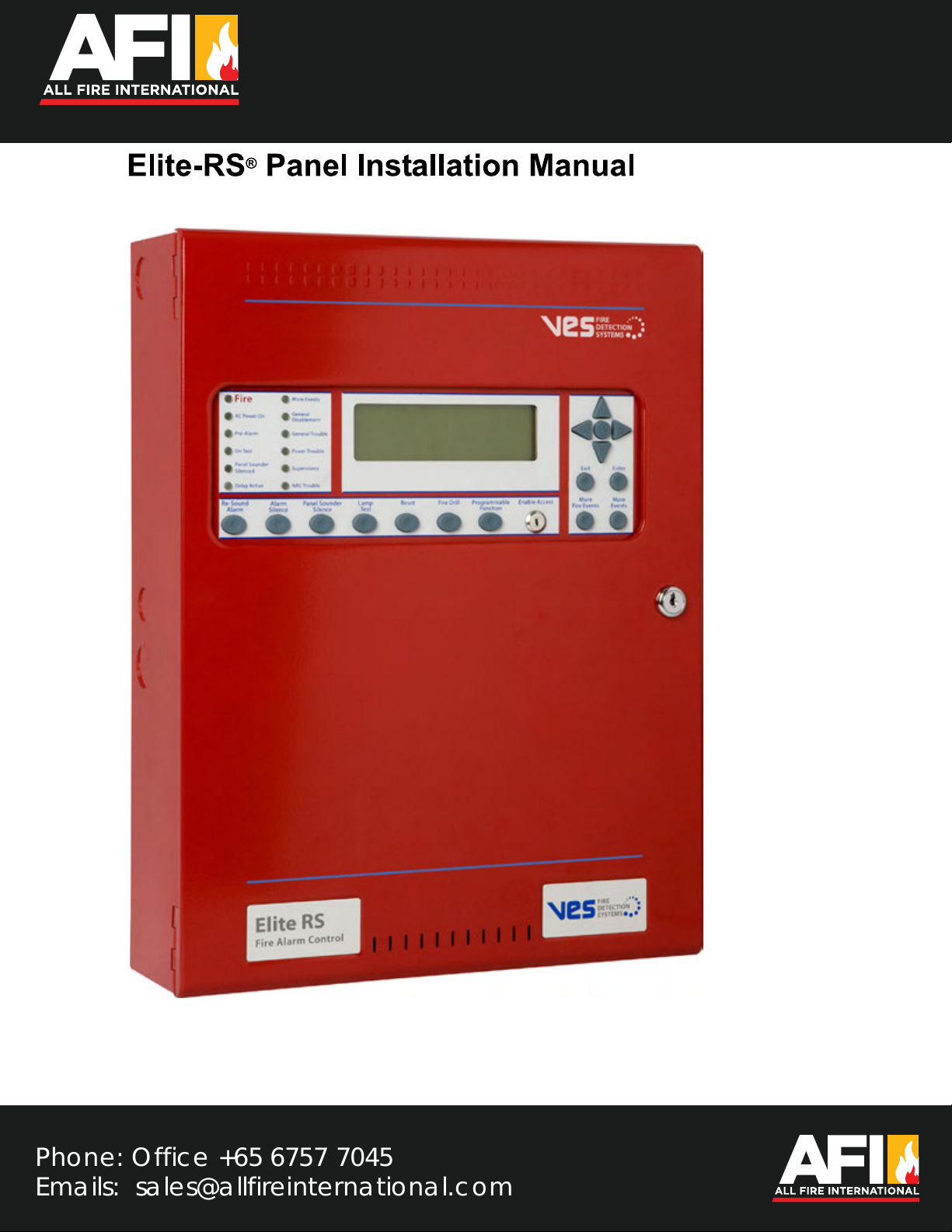
Elite-RS Panel Installation Manual VF3529-00, Revision E01.03
H-Series
Underwriters Laboratories (UL)
File number (S 8485)
Fire Alarm Equipment
VES, LLC
The VES Elite-RS Panel is suitable as follows:
• Local Signaling Unit
• Releasing for eLAN-RS Panels only. Non-Releasing for Elite-RS Panels.
• Types of signaling services are automatic fire alarm, manual fire alarm, waterflow alarm and sprinkler supervisory.
• Style 4, 6 or 7 for Signaling Line Circuits
• Style Y for Notification Appliance Circuits
• Non-coded Signaling, DACT requires Integrated Dialer
• Remote Station (RS) Protected Premises Unit (PPU) provides releasing, non-releasing and VESNet communication on models
(VFXX24, VFXX44, VFXX04) containing the Modem-DACT Ethernet (VFYY04, VFYY05, VFYY08, VFYY09), integrated Dialer or on models
(VFXX21, VFXX41, VFXX01) containing the Media Gateway
• Central Station (CS) Protected Premises Unit (PPU) provides releasing, non-releasing and VESNet communication on models
(VFXX24, VFXX44, VFXX04) containing the Modem-DACT Ethernet (VFYY04, VFYY05, VFYY08, VFYY09), Integrated Dialer or on models
(VFXX21, VFXX41, VFXX01) containing the Media Gateway
• Models (VFXX22, VFXX42, VFXX02) containing the NIC, must be connected (networked) to the VESNet with models (VFXX21, VFXX41,
VFXX01) containing the Media Gateway to communicate to a Remote Station Protected Premises Unit, Proprietary Protected Premises Unit or
Central Station Protected Premises Unit. The VESNet LCD Display (VF8300) with or without the LED ADD-ON Annunciator (VF8203) may also be
connected to the VESNet (networked) with the above models
• Proprietary (P) Protected Premises Unit (PPU) provides releasing, non-releasing and VESNet communication on models (VFXX24,
VFXX44,VFXX04) containing the Modem-DACT Ethernet, (VFYY04, VFYY05, VFYY08, VFYY09) Integrated Dialer or on models (VFXX21,
VFXX41, VFXX01) containing the Media Gateway
• Remote Station (RS) Protected Premises Unit (PPU) provides releasing, non-releasing and eNet communication on models
(VFXX24, VFXX44, VFXX04) containing the Modem-DACT Ethernet or on models (VFYY04, VFYY05, VFYY08, VFYY09) containing the
integrated Dialer
• Central Station (CS) Protected Premises Unit (PPU) provides releasing, non-releasing and eNet communication on models
(VFXX24, VFXX44, VFXX04) containing the Modem-DACT Ethernet or on models (VFYY04, VFYY05, VFYY08, VFYY09) containing the
Integrated Dialer
• Proprietary (P) Protected Premises Unit (PPU) provides releasing, non-releasing and eNet communication on models
(VFXX24, VFXX44,VFXX04) containing the Modem-DACT Ethernet or on models (VFYY04, VFYY05, VFYY08, VFYY09) containing the
Integrated Dialer
“XX” shown in the model numbering above denotes control panel type where “XX” is “09” for eLAN-RS Panels and “08” for Elite-RS Panels.
“YY” shown in the model numbering above denotes control panel type where “YY” is “04” for H-Series eLAN-RS Panels, “05” for A-Series eLAN-RS
Panels, “08” for H-Series Elite-RS Panels and “09” for A-Series Elite-RS Panels.