Fire-Lite IPDACT User manual

IP Communicator
IPDACT
Installation Manual
Document DM373-I
Version 2.0
March, 2007

i
Table of contents
I - Chapter. Introduction................................................................... I-1
I - 1. IPDACT Introduction......................................................... I-1
I - 1.1. User Scenario........................................................ I-1
I - 1.2. Operation Mode..................................................... I-3
I - 1.2.1. Monitoring................................................... I-3
I - 1.2.2. Alarm sending............................................. I-5
I - 1.3. Additional features................................................. I-6
II - Chapter. IPDACT Description...................................................... II-7
II - 1. General Description ......................................................... II-7
II - 2. LEDs .............................................................................. II-10
II - 3. Jumper........................................................................... II-11
II - 4. Connection points to the Control Panel and external..... II-11
II - 5. LAN................................................................................ II-13
II - 6. Console.......................................................................... II-13
III - Chapter. Installation and cabling............................................. III-17
III - 1. Installation..................................................................... III-17
III - 1.1. Assembly Instructions for the IPDACT box........ III-19
III - 2. Wiring............................................................................ III-20
III - 2.1. Wiring for UL Listed Fire Installations ................ III-20
III - 2.1.1. Installation scheme................................. III-20
III - 2.1.2. Installation instructions ........................... III-22
IV - Chapter. Configuration............................................................. IV-27
IV - 1. Configuration modes..................................................... IV-27
IV - 2. DHCP............................................................................IV-27
IV - 3. Telephonic Console ...................................................... IV-29
IV - 3.1. Configuration...................................................... IV-30
IV - 3.1.1. Default Configuration.............................. IV-32
IV - 3.1.2. Register description................................ IV-32
IV - 3.1.3. Minimum configuration for the installer...IV-38
IV - 3.1.4. Configuration Example ........................... IV-39
IV - 4. Asynchronous Console ................................................. IV-41
IV - 4.1. Accessing the console.......................................IV-41

ii
IV - 4.2. Main Menu......................................................... IV-41
IV - 4.3. IPDACT generic configuration............................ IV-42
IV - 4.4. Monitoring configuration and sending of alarms.IV-42
IV - 4.5. IPDACT Quick Configuration ............................. IV-43
IV - 4.6. Monitoring.......................................................... IV-44
IV - 5. Telnet............................................................................IV-46
V - Chapter. Appendix .....................................................................V-47
V - 1. UL Compliance............................................................... V-47
V - 2. Control Panels................................................................ V-47
V - 3. Technical Specifications................................................. V-48
The manufacturer reserves the right to introduce changes and
improvements to the appropriate features of both the hardware and
the software of this product, modifying the specifications included in
this manual without prior notice.

IPDACT - Introduction
I-1 Doc.Dm373-I
Rev. 2.0
I - Chapter.
Introduction
I - 1. IPDACT Introduction
The IP module (IPDACT) is adevice which, when connected to asecurity
control panel, carries out three basic tasks:
•To send over an IP network the alarm information sent by the panel
to which this is connected.
•To check the connectivitybetween the control panel and the alarms
reception center.
•In cases where it is not possible to transmit over the IP network, the
IPDACT will stop intercepting the alarms from the panel. At this
point the alarms will be sent over the telephone line.
The IPDACT operates together with the Teldat VisorALARM device, located
in the alarm receiver center. This behaves as an alarm receiver which
receives the alarms through an IP network (instead of the traditional public
switch telephone network) and sends them through aserial port to automation
software in order to be processed. Additionally, this receives monitoring
messages from multiple IPDACT and generates the corresponding alarm in
cases where communication fails with one or more of these. For further
information on howthe IP VisorALARM receiver operates, please see
manual Dm 357-I.
I - 1.1. User Scenario
Atraditional securityscenario consists of acontrol panel (CP), located in the
client environment and an alarm receiver center (ARC) located in the security
company’s control center. The CP contains agroup of sensors which trigger
aseries of alarms or events which, when produced, are sent to the ARC to be
processed.
Communication between the above is traditionally carried out over the
telephone line so that both ends can initiate a call to the remote end: the CP in
order to notify events and the ARC for bi-directional tasks (activation,
teleloading and general control).

IPDACT Module - Introduction
I-2 Doc.Dm373-I
Rev.2.0
The communication protocol varies depending on the manufacturers who
usually tend to use their own solutions. The IPDACT supports Contact-ID
protocol.
The CP is placed as the first connection element to the PSTN so that it can
prioritize the customer’s telephone line.
Public Telephony
Switched Network
Alarm
Control Panel
Client
Alarm Receiver
Sur-Gard/Radionics Automation SW
IBS/ MAS/ MicroKey
Fax
Alarm Receiver Center
Figure 1. Traditional security scenario
Within the general user scenario, the IPDACT device is located in the client
area, next to the control panel, intercepting the telephone line. This is
displayed in Figure 2.The arrowin the figure demonstrates the preferred
path to send alarms from the CP; here the telephone line is used as abackup
in case there is a communication malfunction in the IP network.
Public Telephony
Switched
Network
Alarm
Control Panel
Client
hechopor M.A. Berrojo
Teldat
C
Intenet
router router
Eth 10 Mbps
Eth 10 Mbps
Alarm Receiver
Sur-Gard/Radionics
Visor Alarm
Automation SW
IBS/ MAS/ MicroKey
hechopor M.A. Berrojo
Teldat
C
Fax
MI P
Alarm Receiver Center
hechopor M.A. Berrojo hecho por M.A. Berrojo
@Teldat
Visor Alarm
Figure 2. Teldat VisorALARM and IPDACT operating scenario
From firmware release 2.2 onwards, the IPDACT has a newfunctionality
incorporated giving rise to a third possible scenario: network backup. In the
previous scenario, where communication fails between the device and the
ARC, the IPDACT hands over the communications to the control panel. With
the newfunctionality, the IPDACT tries to open communications with a second
device, the backup VisorALARM. Onlyin cases where there are problems
with this second device does the control panel take over. Meanwhile, even in
this state, the IPDACT continues to tryand communicate with the ARC until
one of the VisorALARMs responds.

IPDACT Module - Introduction
I-3 Doc.Dm373-I
Rev.2.0
In UL compliance installations, the IPDACT must have firmware
version 4.0.
Figure 3. Network backup function scenario.
I - 1.2. Operation Mode
The IP Module (IPDACT) connected to the client control panel carries out two
tasks: sending alarms from the panel and monitoring the connection with the
IP receiver. The network backup option has implications in connection
monitoring. The alarms reception center is composed of two VisorALARM
devices, one main and the other backup. The IPDACTs release 2.2 onwards
has had their monitoring procedures modified in order to contemplate the
presence of two devices in the central.
I - 1.2.1. Monitoring
The IPDACT is adevice that intercepts the control panel telephone
connection with twoaims: firstlyto detect when the panel sends an alarm in
order to capture it and retransmit over the connected IP network and secondly
to allowthe telephone line to be used at the same time as sending alarms.
The interception of the telephone line takes place ONLY in cases where
connectivity with either of the Teldat VisorALARM devices has been verified.
The IPDACT-VisorALARM connectivity is checked through atraffic monitor
which the IPDACT periodically sends and to which the main Teldat
VisorALARM responds. (Through configuration, the main VisorALARM IP

IPDACT Module - Introduction
I-4 Doc.Dm373-I
Rev.2.0
address is given to the IPDACT and is the primary communication option.
The backup VisorALARM IP address is also configured and is used in cases
where the main device fails). If the exchange of messages does not occur
during the configured time, the IPDACT tries to resend. If, after a configurable
number of attempts, asatisfactoryresponse is not received, the connectivity
with the main VisorALARM is presumed lost. At this point the IPDACT tries
to communicate with the backup VisorALARM,to which it will nowtryand
send the alarms, polls, etc. In cases where communication with this second
device also fails, the telephone line access is returned to the control panel as
if the IPDACT was not present. From this point on, the IPDACT will try to re-
establish communications both with the main Teldat VisorALARM and the
backup, communication with the main device taking priority.The moment
communications are reestablished with either of the twoARC devices, the
IPDACT intercepts the telephone line once more.
The supervision traffic is encrypted UDP. The Ethernet frame size does not
exceed 70 bytes. The monitoring interval, the number of retries and time
between retries are all configurable, and are values that must be carefully
considered. Normally the monitoring interval in the control panel is high as
this implies atelephone call. However, in the case of IPDACT, this cost is
irrelevant as it is dealing with traffic which in all likeliness is running over aflat
rate connection. In addition, a high value here is not advisable in cases where
the IPDACT connects to Internet through arouter executing NAT, avery
probable situation. This is because traffic coming from the ARC towards the
IPDACT reaches this thanks to the router maintaining the entryin the NAT
table active during aperiod of time, the entry being refreshed with supervision
traffic. If the supervision interval is greater than the residence time for the
entryin the NAT table, communications from the ARC will not be possible.
There is no rule to say howlong an entry in the NAT table must last for. In
cases of the TELDAT devices, this is around 5minutes. Alowvalue has the
problem that the traffic the VisorALARM must process is high, the same as
the bandwidth requirements. If ARC Internet access is ADSL, you need to
consider that the upstream channel is smaller than the downstream one and
that supervision traffic returned to the IPDACTs is slighter larger than the
incoming.
The incoming traffic to the ARC is:
mipsALIVEKEEP NTC **528 −
=
The minimum supervision time can be 1second and aVisorALARM can have
3000 IPDACTs registered that give an input traffic of 1,58 Mbps. The return
traffic is approximately 6% larger.
The Teldat VisorALARM received monitoring messages from the IPDACTs.
If these are registered, they are assumed alive and an acknowledgement
response is sent to them; if the IPDACTs are not registered, they are ignored.
Periodically the status of all the registered IPDACTs is checked and all those
which have not notified their availability(i.e. those which have not responded

IPDACT Module - Introduction
I-5 Doc.Dm373-I
Rev.2.0
since the last check) an alarm is generated. This is a350 code alarm from
the Contact-ID protocol (Communication trouble)which is received in SwAut.
In order to prevent the Teldat VisorALARM from sending hundreds or
thousands of communication failure alarms when faced with asituation of
general failure of IP traffic reception, the device itself monitors the network
access through echo ICMP packets (ping) to aknownaddress: if the echo
ICMP packets (ping) towards this address fail then acode 356 alarm is
generated from the Contact-ID protocol (Loss of central polling).
Apart from the above codes, the VisorALARM also generates others related
to network backup. For further information on this, please see manual Dm
298-I “VisorALARM Installation Manual”.
I - 1.2.2. Alarm sending
When the IPDACT has connectivitywith the Teldat VisorALARM,the former
intercepts the telephone line and processes all the incoming and outgoing
calls taking place.
The supported alarm sending protocol is Contact-ID. This format sends
alarms through DTMF digits complying with the following format:
AAAA MM QEEE GG CCC S
where AAA is the client number, MM the type of message, Qan event
qualifier, EEE the type of alarm, GG the group or partition number, CCC the
zone number and lastly Sis the frame validation digit.
When the panel opens to send an alarm, the IPDACT provides power and
emits the dialing tone. When the control panel dials the alarm center
telephone number, it issues the Contact-ID handshake and receives the alarm
frame. From this point, the IPDACT sends this alarm to the VisorALARM.
The control panel is not given the frame sent acknowledgement (kissoff)until
the said acknowledgement is received from the Teldat VisorALARM.If the
IPDACT does not receive the acknowledgement within 2seconds, this carries
on resending aconfigured number of times after which connection with the
Teldat VisorALARM is assumed lost and the control panel sends the alarm
over the telephone line. From this point, the IPDACT tries to re-establish
communication with the VisorALARM as previously described. In cases
where the network backup functionalityis operative, afailure in sending an
alarm to the main VisorALARM changes into an attempt to establish
communications with the backup VisorALARM and to send the alarms to this
second device. If this attempt also fails, then the control panel takes over the
process of sending the alarms.
It’sessential that the total time, in which the IPDACT deactivates in
cases where communications fail with both the IP receivers, is
greater than the control panel’s highest retry time.
The IP VisorALARM receiver on receiving an alarm from an IPDACT stores
this in anon-volatile internal memory.When the operation has successfully

IPDACT Module - Introduction
I-6 Doc.Dm373-I
Rev.2.0
finished, it sends the acknowledgement to the IPDACT originating the alarm
so that in turn this is sent to the associated control panel. If the alarm storage
memorycannot store the alarm, no acknowledgement is given.
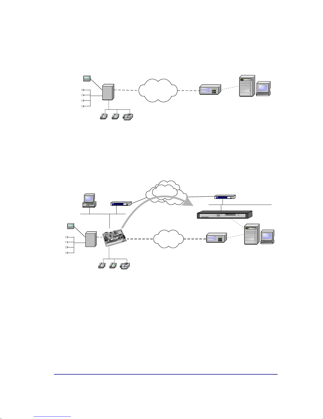
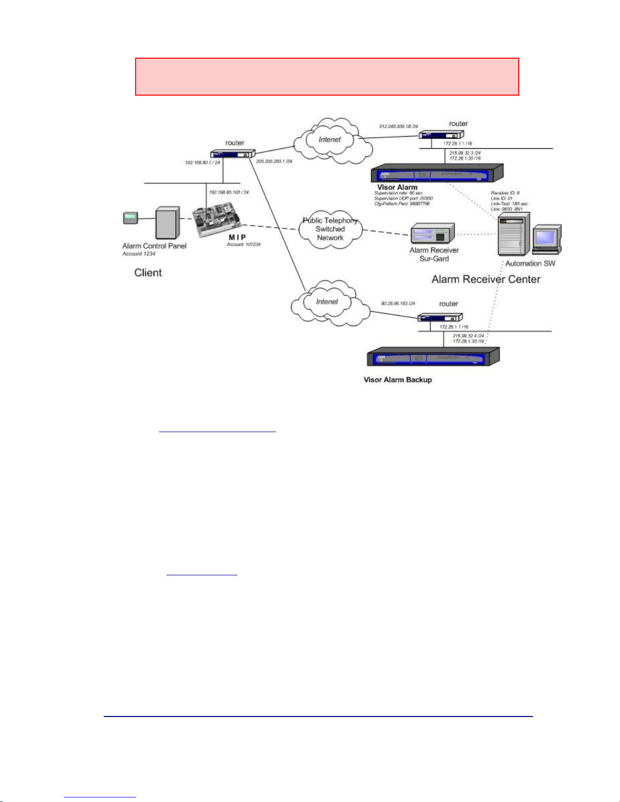
As regards the SwAut, the Teldat VisorALARM behaves as an alarm receiver
that sends alarms received through aserial port. The Teldat VisorALARM
can emulate aSur-Gard, an Ademco 685 or aRadionics 6500 receiver. The
serial line parameters are configurable as well as those relative to the
emulated receiver (link-test, receiver and line identifier, start and end frame
characters, etc.)
I - 1.3. Additional features
In order to simplify installation and updating of the registered IPDACTs, the IP
VisorALARM receiver has additional facilities.
To install new IPDACTs, the Teldat VisorALARM possesses configuration
patterns associated to installer passwords. These permit you to automatically
register new IPDACTs in the supported IPDACT list and at the same time
enable the IPDACT to request the necessary configuration for start up. The
device can simultaneouslyhave multiple patterns; the choice of one or other
depends on the installer password used in the IPDACT to request the service.
In order to maintain and update the registered IPDACTs base, the Teldat
VisorALARM has commands available to remotely update one or multiple
configuration parameters used bythe IPDACTs.
Additionally, in order to simplifythe IP parameters configuration, something
that is not alwayseasy, the IPDACT has aDHCP client program, release 2
onwards, which attempts to automatically obtain all the IP connectivity
information (address, mask and gateway) on startup. To do this, you need to
have aDHCP server in the local network. If the IPDACT does not
automatically obtain the IP address, use the parameters that have been
statically configured, permitting you to make sure that the device operates
even when the said server is down. From release 2.2 onwards, the DHCP
client can be deactivated.
With the aim of adding to point 38.1.5 on UL864, the IPDACT allowstrouble
signaling to be sent to amaintenance VisorALARM receiver, which is a
different device from the main and backup VisorALARMs. The IPDACT
does not discriminate between sending to one receiver or another
depending on the type of signal (alarm or trouble), but sends the same
signal to both the operating receiver and to the maintenance receiver.It
is the receiver’s task to filter the signals to be sent to the automation software.
Receivers that can be configured as maintenance are those containing
firmware version 10.5.16 and superior. These receivers are characterized as
they do not execute IPDACTs supervision functions, nor carry out any remote
operations over the IPDACTs, nor do theyadmit IPDACT registration. These
are repeat alarms coming from the IPDACTs and simply filter the signals,
sending only the required signals to the automation software.

IPDACT Module - Description
II-7 Doc.Dm373-I
Rev. 2.0
II - Chapter.
IPDACT Description
II - 1. General Description
The figure displayed below, represents the IPDACT hardware.
Figure 4. IPDACT
The hardware version and release is identified through its board number
which is TS-540/X where X is the release number.
The following figure shows the identifier details and howto locate it.

IPDACT Module - Description
II-8 Doc.Dm373-I
Rev. 2.0
Figure 5. Board identification details
The IPDACT basically consists of twoelements: the control module and the
telephonic module.

IPDACT Module - Description
II-9 Doc.Dm373-I
Rev. 2.0
Figure 6. IPDACT circuit details.
The device CPU, memory and the LAN (identifiable through the RJ-45
connector) are found in the control module. This manages all the information
procedure and the sending of the information through an IP network over the
LAN.
The telephonic module physically supports the control and contains all the
connection points with the control panel. This manages the entire telephonic
interface with the control panel and the client telephone network (public
telephone network termination point and client phone wiring).
From aconfiguration /monitoring point of view,the IPDACT possesses LEDs
that permit you to viewthe status of the various elements, from the P2 jumper
to control various aspects and atelephonic console. This telephonic console
is accessible from the connection to the control panel (TO-AP) and requires
an analog telephone with tone dialing.
The IPDACT has an asynchronous console which permits you to monitor /
configure the device through an asynchronous terminal.

IPDACT Module - Description
II-10 Doc.Dm373-I
Rev. 2.0
II - 2. LEDs
The IPDACT has three groups of LEDs that provide information on the status
of each type. These are displayed in the following figures:
Figure 7. LEDs and pins for a IPDACT
The LED labeled “ON” (LD1 for all the versions and releases) is green and
indicates that the IPDACT is powered.
Line status LED: Next to the relays there is aLED labeled LD6. In green this
indicates that the telephone relays are active i.e. the IPDACT intercepts the
telephone line. In normal working mode, this only occurs when the IPDACT
has connectivity with the configured VisorALARM.The relays also activate
when the telephone console activates (please see section IV.2 for further
information). When the control panel is executing maintenance tasks due to a
bi-directional call, the relays are inactive.
LEDs LD2, LD3, LD4 and LD 5 each have an independent connotation:
•LED A LD2: Supervision information.
ON: a management frame is sent to the VisorALARM (contact or keep-alive).
OFF: a response is received to the sent management frame. If there is no response,
this remains active, indicating the lack of connectivity with the VisorALARM.
•LED B LD3: TO-AP terminal status
ON: the alarms panel telephone line is off hook.
OFF: the alarms panel telephone line is on hook.

IPDACT Module - Description
II-11 Doc.Dm373-I
Rev. 2.0
•LED C LD4: alarm sending to the VisorALARM.
ON: an alarm has been sent to the VisorALARM.
OFF: a response has been received to the sent alarm.
•LED D LD5: a bi-directional call to the alarm panel is in progress.
ON: there is abi-directional call to the alarm panel. The LED located next to the
relays is off as the alarm panel has directly accessed the telephone line.
OFF: no bi-directional call in progress. The panel is operating normally.
II - 3. Jumper
The bridge labeled P2 operates byshort-circuiting both pins through a metallic
element such as a screwdriver or a clip. This permits two tasks:
a) On device startup this permits you to configure the IPDACT with the
default configuration. For further information on howto activate the
default configuration, please see section IV.2.1.1.
b) Access the telephonic console. This permits you to configure /monitor
the IPDACT through atelephone connected to the said IPDACT. For
further information, please see section IV.2.
II - 4. Connection points to the Control Panel and
external
In order to connect the IPDACT to the control panel and to power this, there is
arowof choc blocks. All the connections are limited in power. As can be
seen in the following figure, the connections are grouped in the following
manner:
Figure 8. Connection choc block
Choc block connection to the control panel

IPDACT Module - Description
II-12 Doc.Dm373-I
Rev. 2.0
•TO-AP: terminals proving telephonic connection to the control panel.
This must be connected to the control panel connection which this is
using to access the PSTN.
•FROM-AP: terminals receiving telephonic connection from the control
panel. This must be connected to the control panel connection which this
uses to provide a line to the subscriber numbers.
Choc block connection to the Public Switched Telephone Network
•PSTN: access terminals to the public switched telephone network. This
connection is supervised. In cases where there is afailure, the analog
output activates.
Choc block connection to the client telephone numbers
•PHONE: terminals providing telephonic connection to the telephone
numbers possessed by the client at home or at installations.
Choc block associated to the analog output control
•OUT NC: terminals whose state is normally short-circuited. On activating
the output, these terminals stop being short-circuited. Short circuit is
carried out through an electric-mechanical relay. The technical data for
this can be found in appendix V.3.
•OUT NO: terminals whose state is normal open. On activating the output
these terminals pass to ashort circuit state. Short circuit is carried out
through an electric-mechanical relay. The technical data for this can be
found in appendix V. 3.
This output is also related to the input status of the PSTN and LAN and with
the IP connectivity status with the alarms reception center. When there is IP
connectivity,the OUT NO terminals will be in their normal state i.e. open. If
there is afailure in IP connectivity,then these terminals pass to aclosed
state.
Choc block associated to an analog input
•INPUT: terminals associated to the input. This input is supervised and
considered inactive when a1K ohms resistance is detected between its
ends. When an open circuit is detected, the device, which should be
connected to this input, is regarded as having been disconnected i.e. it
has been sabotaged.
In UL compliance installations, this input should not be used and
must be bridged with a 1K resistance.

IPDACT Module - Description
II-13 Doc.Dm373-I
Rev. 2.0
Tamper Chock Blocks
•TAMPER: Anadditional input connecting to abox tamper which indicates
if the box is open. The input is normally closed.
Choc block power connections
+12/24V: Itis possible to power the unit at either 12 or 24 volts. For UL
Listed Installations, the power source is regulated, limited in power and
UL compliant.
•GND: power ground terminal.
II - 5. LAN
The device connects to the LAN through an RJ45 (CN1) connector.
Figure 9. LANConnector and cable.
Failure detection in the Ethernet interface is indicated by the analog output
activating.
II - 6. Console
An asynchronous console is available for configuration / monitoring tasks.
The IPDACT has a black RJ45 connected labeled CNI for console connection.
Consequently you will need aDB9 to RJ45 converter for the said connection
which is provided by Fire-Lite. The following figures showboth the converter
and the connector respectively.

IPDACT Module - Description
II-14 Doc.Dm373-I
Rev. 2.0
Figure 10. DB9-RJ45 converter for the console connection
Figure 11. Console connector details
The access configuration is 9600 8N1 (8 bits, without parity, 1 stop bit).

IPDACT Module - Description
II-15 Doc.Dm373-I
Rev. 2.0
The environment is asimple one orientated to menus. The main menu is
displayed in the following figure.
- Main Menu -
Configuration
a) Generic MIP config
b) Remote Alarm report
c) Quick Install
Monitoring
d) General Info
e) Remote Monitor
f) Events
g) IP Connectivity
z) Exit
option:


IPDACT Module – Installationg and cabling
III-17 Doc.Dm373-I
Rev. 2.0
III - Chapter.
Installation and cabling
III - 1. Installation
The IPDACT device is designed to connect aconventional control panel,
which uses the telephone network to transmit alarms, to an IP network. The
module can be connected to a wide variety of panels although only the panels
given in the list in the appendix V.2 should be used for UL compliant
installations.
The IPDACT is installed in a separate box from the panel.
The box is shown in the following figure:
Figure 12. IPDACT Box.
The placement of the IPDACT within the box is as follows:
Table of contents
Other Fire-Lite Cell Phone manuals