Fireco Dorgard Pro User manual

Dorgard Pro
Handbook
Compliance Made Easy
2019-02-20

Contents
Section 1: System overview Page 1
Section 2: Survey Page 5
Section 3: Installation Page 7
Section 8: Troubleshooting Page 11
Section 16: Maintenance Page 18
Section 17: Notes Page 19
Compliance Made Easy

Page 1
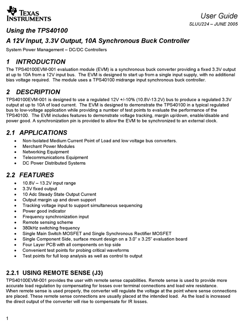
Dorgard Pro is a fire door retainer which holds open fire doors legally,
allowing them to automatically close when a fire alarm is activated.
Dorgard Pro can be acoustically activated or connected to a Transmitter using secure wireless
technology. The radio Transmitter can be directly wired to volt free contacts of a fire alarm relay or
triggered acoustically, processing the sound of the fire alarm and sending a radio signal to Dorgard Pro
allowing them to release the doors.
Part Number Part Name
218-8662 Dorgard Pro Site Survey and Demo Case
360-1551 Dorgard Pro Black
956-8278 Dorgard Pro White
885-3205 Fireco Transmitter
966-2075 Fireco Repeater
System
overview
System
overview

• Overall Height: 205mm
• Casing Height: 150mm
• Width: 195mm
• Depth: 45mm
• Weight: 700g
150mm
205mm
195mm
Dorgard Pro
Page 2
Dorgard Pro is a self contained fire door hold open device which is able to retain a fire
door, at any angle of opening.
Dorgard Pro
Power Two x LR14 C Size batteries
Battery life Five years when radio connected, three years in acoustic
mode
Triggers Fireco Transmitter 885-3205 or acoustically
Radio frequency 433.050 MHz to 434.790 MHz
Applicable door size Up to EN7 160Kg, 1600mm
Fire rating Suitable for timber/composite doorsets up to 120 minutes and
steel doorsets of 240 minutes
Compliant to
EN1155, EN1634, EMC Directive, Radio Equipment Directive,
Critical (Cat A) BS7273-4, when hard wired to a critical
(cat A) system
Radio
Fire
Power
Alert
FR120M
System
overview

Page 3
The Fireco Transmitter is a radio control unit for the Dorgard Pro system. Connecting to
a fire alarm relay or listening to the sound of your fire alarm, it controls and monitors
the system.
Fireco Transmitter
Power 8-30V AC or DC
Battery back-up Two x LR14 C-size batteries, capable of operating system
for 7 days
Triggers Volt free NC/NO/COM or Acoustic
Radio Frequency 433.050 MHz to 434.790 MHz
Range Typically 40-50m
Maximum System Capacity 50 Repeaters and 500 Dorgard Pro
Compliant to EN1155, EMC Directive, Radio Equipment Directive
Operating Temperatures -5 to +70C
• Casing Height: 180mm
• Width: 180mm
• Depth: 48.5mm
• Weight: 532g
180mm !
180mm
!
Radio
Fire
Power
Alert
System
overview

Page 4
System
overview
The Fireco Repeater extends the radio range from the Fireco Transmitter allowing you to
connect more units over a greater distance. Up to 50 Fireco Repeaters may be used in
any installation.
Fireco Repeater
Power 8-30V AC or DC
Battery back-up Two x LR14 C-size batteries, capable of operating system
for 7 days
Triggers Fireco Transmitter
Radio Frequency 433.050 MHz to 434.790 MHz
Range Typically 40-50m
Maximum System Capacity 8 Repeaters and 120 Dorgard Pro
Compliant to EN1155, EMC Directive, Radio Equipment Directive
Operating Temperatures -5 to +70C
• Casing Height: 180mm
• Width: 180mm
• Depth: 48.5mm
• Weight: 532g
!
180mm
180mm
!
Radio
Fire
Power
Alert

1. Switch your Dorgard Pro Demo & Site Survey
Transmitter into survey mode by flicking the switch
on the base of the Survey Transmitter to the right.
2. Press down the plunger on your Demo
Dorgard Pro. This will sync the two units and
enable you to survey a building.
!
3. Place the Survey Transmitter where you are
proposing to install the Fireco Transmitter. This should
be within 2 metres of the fire alarm relay if you are
planning on directly connecting the Transmitter.
If proposing an acoustically activated Transmitter,
place the Survey Transmitter where it is able to hear
the sound of the fire alarm above the background
noise. Do not site Transmitters within 1 metre of power
sources or metal surfaces (including Georgian
wire glass).
https://goo.gl/CMxYW8
Dorgard Pro
!Dorgard Pro
!
1
Page 5
Surveying a
building prior to
installation
Survey

7. Assess a position for the required Fireco Repeater
to be installed, i.e. not within 1 metre of a power source
or metal surface (including Georgian wire-glass).
8. Move your Fireco Survey Transmitter to this new
position and repeat the first steps of the survey until you
have a positive radio range reading at each door you
require to be held open with Dorgard Pro.
Repeat this process for all of the doors you wish to cover. If at
a door position the Dorgard Pro gives a red LED indicating it is
no longer in range of the Survey Transmitter, the installation will
require a Fireco Repeater to be located at the end of the range.
4. Place the Survey Dorgard Pro at the position a
Dorgard Pro is to be fitted. Ensure you hold it at
the bottom of the fire door with the rubber foot
touching the floor. Press the plunger down to get a
radio reading. If the Dorgard Pro is in range of the
Survey Transmitter the top LED of the Dorgard Pro
will flash green for 4 seconds. If the Survey Dorgard
Pro is no longer in range it will flash the top LED
red for 4 seconds.
6. To identify a suitable location for the new Repeater bring
the Survey Dorgard Pro closer to the Survey Transmitter
until you are again in range (confirmed by getting a green
light on the top LED of the Survey Dorgard Pro after you
press the plunger down).
!Dorgard Pro
!Dorgard Pro
!Dorgard Pro
!Dorgard Pro
!Dorgard Pro
!Dorgard Pro
!Dorgard Pro
Dorgard Pro
!
!Dorgard Pro
Dorgard Pro
!
!Do
Page 6
Survey

Option 3. Connect to another source such as the
auxiliary power from the fire panel. The power
supply must be between 8v and 30v (AC or DC).
Connect the green two way terminal block into the
two way green connector located at the base of the
Transmitter or Repeater.
The Transmitter or Repeater will beep twice and
the power LED on the label will show a green
light to say it has been successfully powered. The
Transmitter will carry out its channel scan indicated
by a flashing amber radio LED.
Power
Dorgard Pro
Dorgard Pro is supplied with two C-size batteries. To replace the batteries,
unscrew the battery compartment on the top face of Dorgard Pro using
an PZ2 screwdriver. Lift the battery shaft out and insert two new batteries
positive up.
Transmitter & Repeater
Provided
• EZ6016 24V 1A DC Power Supply with 2-way terminal block
• EC7922 Power cable C7 with stripped ends
• EC5217 UK plug adaptor
• EC2083 EU Plug adaptor
• EC0000 AU Plug adaptor
The Transmitter and Repeater require 8-30V AC or DC.
Connecting to power
https://goo.gl/XQyoHw
Page 7
Installation
Option 1. Using the supplied power supply EZ6016
connect either the UK, EU or AU plug adaptor by slotting
one into the fixing point.
Option 2. Fit the C7 power cable EC7922 into the Power
Supply EZ6016 at the base of the unit and connect to a
non-switched fused 1A spur.
8-30V ac/dc
https://goo.gl/V2HjZd

The Transmitter is factory set to be triggered
acoustically by the sound of the fire alarm. The
resistor factory fitting across the green three way
terminal block denotes the Transmitter is in Acoustic
Mode.
Remove green three way terminal block from the base of
the Transmitter.
Remove resistor from the green three way terminal block.
Wire the COM NC NO from the volt free contacts of the
fire alarm relay into the green three way terminal block.
Connect the green three way terminal block into the
corresponding green three way connector on the base of
the Transmitter.
Connecting
Transmitter to fire
alarm CIE relay
C NO NC
FIRE ALARM
C NO NC
https://goo.gl/vL546L
https://goo.gl/RmafKZ
Page 8
Installation
Setting up an
acoustically-activated
Transmitter

3. Press the bind button on the base of the
Transmitter or Repeater once you have successfully
bound all of the Dorgard Pro.
Binding a
Dorgard Pro
to a Transmitter
or Repeater
4
4
https://goo.gl/dMvJ77
Page 9
2. Insert an object <3mm diameter and press the bind
button in the hole located to the left of the label on
the front of Dorgard Pro. The top radio LED will flash
green until it has found and bound to the Transmitter or
Repeater. It will then show you a constant green radio
LED for 4 seconds.
1. Press the blue bind button on the base of
the Transmitter or Repeater. This will put the
Transmitter/Repeater in bind mode, indicated
by the top radio LED flashing green, and allow
Dorgard Pros and Repeaters to be bound to it.
The Transmitter/Repeater will stay in this mode
for one hour or until you press the bind button
for a second time. The radio LED will then
stop flashing.
Installation

Binding a Repeater
to a Transmitter or
Repeater
1. Press the blue bind button on the base of the
Transmitter or Repeater. This will put the Transmitter/
Repeater in bind mode (indicated by the top radio
LED flashing green) and allow Repeaters to be
bound to it.
2. Once the Repeater has successfully bound to
the Repeater or Transmitter it will stop flashing
the top radio LED green and come out of
binding mode. When the Repeater is
successfully bound it will carry out a channel
scan, this is indicated by a flashing amber
power LED.
Press the blue bind button on the Transmitter or
primary Repeater again to take the unit out of
binding mode and allow you to bind further units
to the recently bound secondary Repeater.
4
4
https://goo.gl/ZrzuGd
Page 10
Installation

Troubleshooting section
Section 8: Failing to bind Page 11
Section 9: Amber radio LED on the Transmitter Page 13
Section 10: Red radio LED on Repeater Page 14
Section 11: Amber radio LED and amber flashing fault LED
on Transmitter/Repeater Page 14
Section 12: Detach Page 15
Section 13: Factory reset Page 16
Section 14: Dorgard Pro is marking the floor Page 17
Section 15: Dorgard Pro is slipping on the floor Page 17
Compliance Made Easy
Scan to watch our
technical support videos

Failing to
to bind
Dorgard Pro
State
Dorgard Pro will show you it has unsuccessfully bound
by showing you the radio LED as red for 4 seconds.
It will then take itself out of binding mode and remain
in acoustic mode.
If Dorgard Pro again lights its radio LED red (4s) it has unsuccessfully bound to the Transmitter or
Repeater.
You will need to re-site the Transmitter or Repeater closer to the Dorgard Pro
OR bind the Dorgard Pro to a different Repeater
OR add another Repeater to your system to increase the coverage.
Check
Check that the Transmitter or Repeater to which you
want the Dorgard Pro to bind is in binding mode.
The Transmitter or Repeater will be flashing its top
radio LED green.
Fix
While the Transmitter or Repeater is in binding mode,
try pushing the bind button on the Dorgard Pro again.
The Dorgard Pro will flash its top radio LED green and
retry binding to the Transmitter or Repeater.
Dorgard Pro
!
!Dorgard Pro
4
Page 11
Troubleshooting

Page 12
Repeater
State
The Repeater is still flashing its top radio LED
green 1 minute after the bind button on the base
of the Repeater has been pressed down.
Check
Press the bind button on the Repeater again. If the
top radio LED stops flashing it has bound to the
Transmitter or primary Repeater.
OR Check that the Transmitter or primary Repeater is
in bind mode, displayed by the top radio LED flashing
green.
Failing
to bind
Fix
You will need to move either the Transmitter or Primary
Repeater closer to the Secondary Repeater.
OR move the Secondary Repeater closer to the Transmitter or Primary Repeater
OR bind the Secondary Repeater to a different Repeater
OR add another Repeater to your system to increase the coverage.
4
!
Dorgard Pro
!
!
Troubleshooting

Page 13
Fix
Push the plunger down on each of these Dorgards,
if lost communication temporarily they will attempt
to rebind automatically. If successful this will clear
the amber LED on the Transmitter and both amber
LEDs on the Repeater.
If the plunger fails to stay down and the Dorgard shows
red radio LED and red alert LED then it has failed to
rebind and will need detaching and rebinding. If it does
not rebind then an additional repeater may be required.
Amber radio LED
on the Transmitter
State
The top LED is amber on the Transmitter. This indicates
it has lost communication with one or more of the
devices that are bound to it indirectly (if it was directly
bound to the lost device the alert LED would also be
flashing amber, section 11).
Check
Repeaters;
If the top LED is red it has lost its communication with its Transmitter/Repeater that it receives its
signal from (ie its parent device).
(Transmitter/Repeater - see section 10).
If the alert LED is flashing amber with radio amber then check all the devices directly bound to it.
Dorgard Pro
!Dorgard Pro
!
Troubleshooting

State
This is indicating the Repeater is no longer in
communication with its parent device (Transmitter or
Repeater). All the devices that are bound to the Repeater
will also show lost communication fault.
Fix
Check the parent device to check for faults and that its
powered. If there are no faults, it may be necessary to
move the Repeater closer to its parent device or fit an
additional Repeater to bridge the distance.
Red radio LED
on Repeater
State
Indicates that one or more of the devices DIRECTLY bound
to it has lost communication.
Check
Repeaters. If showing red radio LED see section 10.
Dorgards. Push the plunger down on each of the Dorgards,
if lost communication temporarily they will attempt to rebind
automatically. If successful this will clear the both amber
LEDs on the Repeater.
If the plunger fails to stay down and the Dorgard shows red
radio LED and red alert LED then it has failed to rebind and
will need detaching and rebinding. If it does not rebind then
an additional Repeater may be required to bridge
the distance.
Amber radio LED and amber
flashing fault LED on
Transmitter/Repeater
Page 14
Troubleshooting

Detach
Detach
In order to remove a Dorgard Pro or Repeater from a
network, hold the bind button down on the products you wish to detach, until the top radio LEDs show
amber. Whilst they are showing amber, they are detaching themselves from the network. Once they have
finished detaching, they will no longer show amber, and Dorgard will revert back to acoustic. Press the
bind button again to stop the detach process.
If you are detaching a Repeater from a network which has other Repeaters or Dorgard Pro bound to it,
they will lose communication and go into a fail to safe state, releasing any doors they are holding open.
They will continue to be bound to the Repeater, however, and will no longer retain any doors until the
Repeater is re-bound to a Transmitter or Repeater which is connected (acoustically or wired) to a fire
alarm relay.
Detaching is a way of removing a Repeater or
Dorgard Pro from the network.
One way detach on
Transmitters/Repeaters
It may be that the Repeater or Transmitter which the Dorgard
Pro or Repeater is bound to is no longer operational, in which
case you cannot unbind from both products.
If this happens hold the bind button in until the top radio LED
flashes amber. It will continue to flash amber whilst it clears
any lost devices. This can take several minutes. The amber
LED will go solid temporarily when cleared, then continue to
flash. Turn off detach by pressing bind button.
To carry out a one way detach on a Dorgard, factory reset it.
(see section 13.)
4
https://goo.gl/Zpnjqo
Page 15
Troubleshooting

Dorgard Pro
1. Remove the batteries.
2. Hold the bind button in whilst putting the batteries back in.
3. Release the bind button after Dorgard Pro beeps 3 times.
Factory reset
Transmitter & Repeater
1. Remove power.
2. Remove the bottom and top covers.
3. Remove one of the batteries.
4. Replace the power whilst holding down the
bind button.
5. Wait for three beeps, to indicate the Transmitter
or Repeater is reset.
6. Replace battery.
Dorgard Pro
!x3
https://goo.gl/kTmrjh
https://goo.gl/kTmrjh
!
x3
Performing a factory reset returns the product to the original
system state by erasing all of the information stored. This
restores the device’s software to its original manufacturer
settings.
After carrying out a factory reset, the device will lose all of its
retained memory so will no longer be bound to or control any
products. It will no longer retain any doors until it is re-bound
to a Transmitter or Repeater which is connected (acoustically
or wired) to a fire alarm relay.
Page 16
Troubleshooting

Check
Check the rubber foot is making good contact with
the floor and the plunger is fully pressed down.
Fix
Resite the Dorgard Pro lower on the door to ensure
the rubber foot makes good contact with the floor.
OR Install a Dorgard Floorplate
Dorgard Pro
is marking
the floor
Dorgard Pro
is slipping on
the floor
Press and release the plunger 5 times
within 1 minute. Wait for 2 beeps.
This will activate the anti-drag feature so when the
door is pulled, Dorgard Pro will release the door.
Use the QR code (above right), to view our video of how
to turn the anti-drag feature on or off.
4
x2
x5
<1min
https://goo.gl/4F5JnS
https://goo.gl/cNDrMG
Page 17
Troubleshooting
Other manuals for Dorgard Pro
1
Table of contents
Popular Controllers manuals by other brands
Lambario
Lambario LAMBARIO-RF-SMARTLINE-RGB user manual
Sealey
Sealey ECS350 instructions
Aaeon
Aaeon AEC-6915 manual
Mitsubishi Electric
Mitsubishi Electric MELSEC FX3U Programming manual
Stanford Research Systems
Stanford Research Systems LDC500 Operation and service manual
Watlow
Watlow PM LEGACY PM3 user guide
