Fireye UC485 User manual

1
DESCRIPTION
TheUC485isanopticallyisolatedUSBtooneportRS-422/485converter.Theprovidedcable
plugsintoanyavailableUSBportonyourcomputerorUSBhubandthedevicewillshowupasan
additionalCOMportintheWindowsDeviceManager,makingtheUC485compatiblewithWin-
dowsapplications.TheUC485isanUSBtoRS485converterthatdrawspowerfromtheUSBport
sonopowersupplyisrequired.
TheUC485isanaccessoryfortheFireye®BurnerLogix,FLAME-MONITOR™andMicroM
flamesafeguardcontrolsystems,theNEXUSsystemwhenusingaComFireoranNXMBI,the
45FS1and45UVFS1FlameSignatureScanners™andthe95IRS2,95UVS2and95DSS2InSight
integratedscannersandthe105F1-1Paragonscanner.
Opticalisolationoffersasignificantimprovementinnoiseimmunityandimprovesreliabilityin
communicationsthroughput.TheUC485isanUSBtoRS485converterusedtoperformthefollow-
ingfunctions:
1.
CustomizetheoperatingcontrolmessagesandlockoutalarmmessagesoftheYZ300Interlock
AnnunciatoruseintheBurnerLogixYBandZBsystems.
2.
CustomizetheoperatingcontrolmessagesandlockoutalarmmessagesoftheE300Expansion
ModuleusedintheFLAME-MONITORsystem.
3.
InterfacebetweenaWindowsbasedPCrunningtheFS700WCommunicationSoftwareandthe
45FS1and45UVFS1FlameSignatureScannertoprovideremotecommunicationscapability.
4.
InterfacebetweenaWindowsbasedPCrunningtheFS950WCommunicationSoftwareandthe
95IRS2,95UVS2and95DSS2InSightintegratedscannerstoprovideremotecommunications
capability.
5.
InterfacebetweenaWindowsbasedPCrunningtheE720WBoilerWorxCommunicationSoft-
wareandtheE340BurnerManagementControlSystemtoprovideremotecommunications
capability.
6.
InterfacebetweenaWindowsbasedPCrunningtheComFireNEXUSCommunicationSoft-
wareandtheNEXUSparallelpositioningcombustioncontrolsystemstoprovideremotecom-
municationscapability.
7.
InterfacebetweenaWindowsbasedPCrunningthePGEXLT(ExplorerLite),FEX1(Fireye
Explorer)CommunicationSoftwareandthe105F1-1Paragonor95DSS3InSightIIintegrated
scannerstoprovideremotecommunicationscapability.
TheUC485providesthemeanstodirectlyconnecttoanydevicethathasRS485communication
capability.
TheUC485ispackagedwithanRJ12telephonejackmountedonaPCboard,(ED612),toprovide
aneasymethodtousetheED512cablestointerfacetotheBurnerLogixsystemincludingthe
YZ300/YZ320InterlockAnnunciatorsandEPprogrammersforcustomizingmessages.
TheUC485includesTRANSMITandRECEIVELED’sthatindicatethetransmissionandreception
ofdatarespectively.TheLED’sarealsousefulwhenfirstconfiguringasystem.
UC485
OPTICALLY ISOLATED
USB to RS422/RS485
CONVERTER
UC-4851
APRIL 8, 2013

2
RS-485 Control
No special software is required to control the RS-485 receiver or transmit line driver. The driver is
automatically enabled during each byte transmitted in RS-485 mode. The transmitter is always
enabled in RS-422 mode. The receiver is tri-stated during each byte transmitted in the echo-off
mode. The receiver is always enabled in the echo-on mode. There are 4.7k Ohm pull-up/pull-down
resistors on the RDA and RDB lines. A termination resistor is usually not necessary but may be
added if needed.
Dip Switch Set-up
Dip switches allow the UC485 module to be configured for two-wire or four-wire, RS-422 or RS-
485 modes. In two-wire mode the TDA(-) and RDA(-) are tied together so are TDB (+) and RDB
(+), making multi-dropping the UC485 converter into an existing network easy.
For use with Fireye equipment it is recommended to have all dip switches set to the ON position.
SPECIFICATIONS
Dimensions: .0.5 x 1.7 x 0.8 in (8.9 x 4.3 x 2.1 cm)
Temperature Range: 0° to 70° C (32° to 158° F)
Rs-422/485 Baud Rate: Pluggable (removable terminal block with ED612
RS-422/484 Connector: 12 Mbps
USB Connector: USB type-B female
USB Power: Low power device (<100 mA)
USB Compatibility: USB 1.0, 1.1 and 2.0
Operating System: Windows 98/SE, 2000, ME XP, Vista, 7
Isolation: 2000 V RMS
Surge Protection: 15KV ESD
Accessories: Driver CD, USB Cable, ED612
Switch OFF ON
One (1) TD always enabled
(TD 422)
TD always enabled during
data transmission
(TD 485)
Two (2) RD always enabled
(ECHO ON)
RD disabled during data
transmission
(ECHO OFF)
Three (3) Four-wire mode
(4-Wire)
Tw o - w i r e m o d e
(2-Wire)
Four (4) Four-wire mode
(4-Wire)
Two-wire mode
(2-Wire)
RS-422
Echo ON
4 Wire
4 Wire
RS-485
Echo OFF
2 Wire
2 Wire
OFF ON
DIPSWITCHES - REAR VIEW

3
INSTALLATION FOR WINDOWS
CUSTOMIZING BurnerLogix YZ300 OR FLAME-MONITOR E300 MESSAGES
You can customize the recycle and lockout alarm message associated with each pair of terminals of
the E300 Expansion Module and YZ300 Interlock Annunciator. Each customized message can be up
to 40 characters in length.
The following equipment is required:
A Windows compatible PC with E300 (Flame-Monitor) or YZ300P (BurnerLogix) programming
software.
UC485 USB to RS485 converter with USB cable.
ED612 with RJ12 connector mounted and wired into terminal block of the UC485.
For E300 messages, an EP programmer with an engineering code of 28 or later.
For BurnerLogix, a YZ300 Interlock Annunciator.
#2. The screen above appears. Make sure Install
the software automatically is selected. Then
select the Next> button.
You may be prompted to BROWSE the CD to
select the correct folder that contains the
proper driver.
#1. Plug the UC485 into an available USB
port on your Windows compatible computer
or connected hub. The screen above appears,
telling you that there is a new device plugged
into the USB bus. Click on No, not this time,
then the Next> button.
#3. The screen above will appear. Click the
Finish button to complete the installation. #4. Continue to install the serial port in the
same way as installing the converter. Click
the Next button followed by the Finish but-
ton. It takes a couple of seconds for the serial
port to be installed.
4
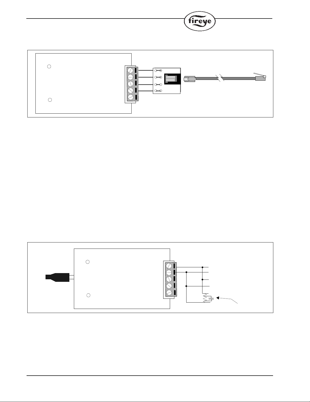
1. Connect the UC485 converter to an available USB port of a Windows compatible computer.
FIGURE 1. .
2. Connect the ED612 (RJ12 female connector provided with the UC485) to terminals TD(A),
TD(B), RD(A), and RD(B) on the UC485
3. Plug one end of the ED512-2, -4, -8 cable into the jack on the ED612 and the other end into
either of the jacks located on the EP programmer for a FLAME-MONITOR system or directly
into the YZ300 for a BurnerLogix system.
For complete details on customizing the E300 messages, refer to bulletin E-3001.
For complete details on customizing the YZ300 messages, refer to bulletin YZEM-3001.
COMMUNICATING WITH 45FS1/45UVFS1 SIGNATURE SCANNERS OR 95IRS2/95UVS2/95DSS2 AND
95DSS3 INSIGHT II FAMILY OF INTEGRATED SCANNERS OR PARAGON SCANNERS
These flame scanners provide remote communications capability over an RS485 communication
data link. The data link uses a single, twisted shielded pair wire (e.g. Belden 8761) in a multi-drop
(e.g. daisy chain) wiring configuration. A Fireye communication software program running on a
Windows compatible PC is required for communicating with the flame scanners.
Since the flame scanners communicate over the data link via RS485, the UC485 USB/RS485 con-
verter is required for the communications Port of the PC. The UC485 converter is wired in the fol-
lowing manner:
FIGURE 2. UC485 WIRING
GND
TDA (-)
TDB (+)
RDA (-)
RDB (+)
TD
RD
TDA (-)
TDB (+)
RDA (-)
RDB (+)
GND
ED512, -2, -4, -8
ED612
GND
TDA (-)
TDB (+)
RDA (-)
RDB (+)
COM B
COM A
COM B
COM A
(ORANGE)
(BROWN)
COMMUNICATIONS
TERMINATOR 100
ON LAST SCANNER
TD
RD
USB CABLE
COM B
COM A
CONNECT TO
USB PORT ON
PC OR HUB

5
For complete wiring details on wiring and communicating with these flame scanners, refer to the fol-
lowing bulletins:
COMMUNICATING WITH THE E340 BOILER CONTROL
The E340 Boiler Control also communicates over an RS485 communication data link. The data link
uses a single, twisted shielded pair wire (Belden 8761) with the E340 controls wired in a multi-drop
(e.g. daily-chain) wiring configuration. The Fireye communication software program (P/N E720W)
is required for communication with the E340 controls.
Wire the UC485 converter to the E340 controls in the following manner:
FIGURE 3.
SCANNER BULLETINS SOFTWARE BULLETINS
45FS1/45UVFS1
SIGNATURE SCANNER
CU-32 & CU-33 CU-56 (FS700W/WINDOWS)
95IRS2/95UVS2/95DSS2 INSIGHT
INTEGRATED SCANNERS
CU-95 CU-102 (FS950W/WINDOWS)
95DSS3 INSIGHT II INTEGRATED
SCANNERS
CU-113 CU-109 (FEX1/WINDOWS)
105F1-1 PARAGON SCANNERS CU-108 CU-111 (PGEXLT/WINDOWS)
GND
TDA (-)
TDB (+)
RDA (-)
RDB (+)
TD
RD
USB CABLE COM B (TERMINAL 80)
COM A (TERMINAL 81)
COM B (TERMINAL 80)
COM A (TERMINAL 81)
FIRST E340
LAST E340
COMMUNICATIONS
TERMINATOR
P/N 61-6439
CONNECT TO
USB PORT ON
PC OR HUB

6
NOTICE
When Fireye products are combined with equipment manufactured by others and/or integrated into
systems designed or manufactured by others, the Fireye warranty, as stated it its General Terms and
Conditions of Sale, pertains only to the Fireye products and not to any other equipment or to the
combined system or its overall performance.
WARRANTIES
FIREYE guarantees for one year from the date of installation or 18 months from date of manufacture
of its products to replace, or, at its option, to repair any product or part thereof (except lamps and
photocells) which is found defective in material or workmanship or which otherwise fails to conform
to the description of the product on the face of its sales order. THE FOREGOING IS IN LIEU OF
ALL OTHER WARRANTIES AND FIREYE MAKES NO WARRANTY OF MERCHANT-
ABILITY OR ANY OTHER WARRANTY, EXPRESS OR IMPLIED. Except as specifically
stated in these general terms and conditions of sale, remedies with respect to any product or part
number manufactured or sold by Fireye shall be limited exclusively to the right to replacement or
repair as above provided. In no event shall Fireye be liable for consequential or special damages of
any nature that may arise in connection with such product or part.
FIREYEUC-4851
3 Manchester Road APRIL 8, 2013
Derry, New Hampshire 03038 USA Supersedes September 28, 2012
www.fireye.com
Table of contents
Other Fireye Media Converter manuals


