BMR Power Baby 1 User manual
MANUAL
Power Packet
in a small Size:
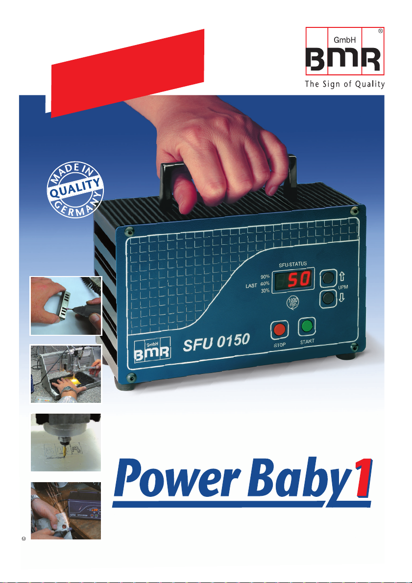
Handheld High Frequency Converter SFU 0150
BMR GmbH 2008

SFU 0150
2
Plea e read
thi manual carefully
before the fir t u e
Version 06.April.2009
Congratulation
for purchasing a BMR-GmbH product.
We thank you for the decision for
choosing a BMR-GmbH device
and wish you much success.

3
Content
1. ntroduction
2. Description and Features
3. Technical Data
4. Safety Precautions and Warnings
5. Connections, Plugs and Pinouts
5.1 Remote Control Connector
5.2 Spindle Connector
5.3 Mains
5.4 Mains Switch and Fuse
6. Functions, Setup, Operation
6.1 Front Panel
6.2 Setup of Rotational Speed
6.3 Starting and Stopping the Frequency Converter
6.4 Setup of Direction of Rotation
6.5 Operation
7. Safety Functions
8. EMC (Electro Magnetic Compatibility)
9. Dimensions SFU0150
10. EG-Declaration of Conformity
11. General Hints
12. Warranty
4
5
6
7
8
9
9
9
9
10
10
11
11
12
12
13
13
14
15
16
17

SFU 0150
4
Depending on its construction, the speed of a three-phase A.C. motor is directly dependent
on the number of poles and the frequency of the network. n a 3ph 380V/50Hz network, with
a 2-pole motor, the rated speed would be 50 U/s * 60 = 3000 Upm.
With D.C. motors (brushless motor D.C.), the speed is dependent on the voltage applied.
Three-phase A.C. motors provide numerous benefits in industry, such as brushless motor
operation, long life, favourable performance/weight ratio, high-speed capability, and much
more. These motors can be used in many different application areas, such as milling and
grinding spindles, or with drilling machinery.
n these mentioned applications, three-phase AC motors are operated using special control
gear - frequency converters. These frequency converters convert the fixed 50 Hz network into
a 3-phase network with variable frequency and voltage. This greatly reduces the start-up
problems and the high starting currents that are unavoidable when high-capacity three-phase
A.C. motors are connected to a fixed network. The motor is controlled according to a special
characteristic curve until its rated speed has increased, or it has been stopped.
The SFU 0150 - series high frequency converter has been specially designed for use in these
high frequency applications, offering excellent safety, performance and reliability, the result
of years of experience in the design and construction of frequency converters, together with
the use of the latest materials and the most reliable components. t can be used in many
different applications and is as suitable for use as a replacement device in existing systems
with older type series as it is in pre-planned applications as a cost-effective solution, helping
to prolong the useful life of tools.
1 Introduction

5
2 De cription and Feature
For the operation of A.C. spindles.
The high frequency converter SFU 0150 allows peed frequencie up to 50,000rpm with
2-pole A.C. spindles. Maximum High output power i (150VA) in a compact de ign.
The core of the SFU 0150 is the Digital Signal Proce or (DSP) which generates all output
signals and captures all input signals.
All parameters, such as current, voltage and frequency, are captured in real time, and are
adjusted according to load condition by Vector Control Mode.
The highe t efficiency of motors at both low and high frequencie is made possible.
Highe t level of operational afety: All operating states such as acceleration, operation at
rated speed, and deceleration, are monitored and critical situations are intercepted and
brought under control automatically.
Di play of Rotational Speed: current load condition and converter status message on
three 7 segment LEDs.
Control: The high frequency converter can be controlled manually using 2 push buttons on
the front panel or via the control input on the rear panel.
Galvanic i olation: spindle voltages and electronics using a mains transformer
Short-circuit-protected
Over-temperature-protected

SFU 0150
6
3 Technical Data
230V, 50Hz, 1PH / 115V, 60Hz, 1PH as option
ON/OFF Switch in combination with a resettable
thermo protection switch as mains fuse 1A/250V
150 VA (max 5 min)
3 prong U, V; W,
3* 36V
Electronically limited
AC: 833Hz /50,000 rpm
Start/Stop with a galvanically isolated contact or a B.M.R foot
controller.
On 3 x 7 segment LED
On 3 x 7 segment LED
As bar graph on 1st 7 segment LED
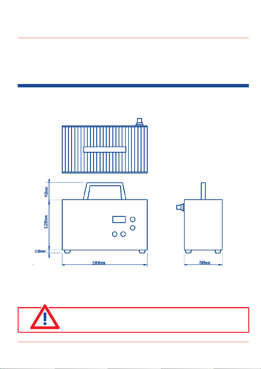
200 x 120 x 105 W x H x D (mm)
App. 2,5kg
P20
ambient temperature 10°C...40°C, max 80% humidity content
Mains connection
Mains Switch
Fuse
Output Power
Spindle Connection
Output voltage
Output current
Output frequency
Control input
Display of rotational speed
Display of status
Display of load condition
Dimensions
Weight
Protection
Operating conditions
ATTENTION: Make sure that the setup for mains voltage is in
accordance to the power line used.

7
This device produces dangerous electrical voltages and is used
for the operation of dangerous moving mechanical parts.
For this reason, only professionally trained and qualified personnel
should be allowed to install and work with this device!
Any maintenance or repair work on the device must only be
carried out when the mains supply plug has been disconnected!
Before the first activation can be carried out, it should be established
that the tool is installed correctly and securely, to eliminate the
possibility of uncontrolled movement of the motor.
Safety regulations that are valid for the country where the device
is used, must be applied when repair or maintenance work is
carried out on the device.
Maintaining EMC (electro magnetic compatibility) limits is the
responsibility of the manufacturer of the machine or device. The
inputs on this device are fitted with filters, to increase the
interference immunity and to reduce emitted interference, making
it possible to use this device in an industrial environment. The
EMC of a machine or device is affected by all connected
components (cables, wiring, etc.) and for this reason, installation
and connection of the device should only be carried out by
qualified personnel.
4 Safety Precaution and Warning

SFU 0150
8
5 Connection , Plug and Pinout
Spindle Connector
Remote Control
Connector
ATTENTION: Plea e do not connect any external
voltage to the remote control pin !
On/Off Switch in combination
with a resettable fuse

9
Off Position On Position
Pin 1 = to FSW, B.M.R Footcontroler or contact
Pin 2 =
Pin 3 =
Pin 4 =
Pin 5 = to FSW, B.M.R Footcontroler or contact
5.1 Remote Control Connector (5 Pin)
Operation with footswitch
BMR vario footcontroler
Galvanically isolated contact
= ON/OFF.
= ON-OFF- Variable rotational Speed.
= Remote Control by a external PLC
3 pin butterfly mains connector.
The mains switch is realized as a combination between a push-push button mains switch
and a thermo protection fuse for 1A. Exeeding the rated current will trigger the thermo fuse
to switch in the OFF Position
Pin 1 = R
Pin 2 = S 3 Phase for Spindle
Pin 3 = T
5.2 Spindle Connector (3 Pin)
5.3 Main
5.4 Main Switch and Fu e

SFU 0150
10
6 Function , Setup and Operation
6.1 Front Panel
4 Po ibilitie for Operation:
Manually with the buttons on the front panel
Operation with footswitch = ON/OFF
BMR Vario foot controler = ON / variable rot. speed / OFF
Galvanically isolated contact = remote control
ATTENTION: Plea e do not connect any external
voltage to the remote control pin !

11
6.2 Setup of Rotational Speed
The rotational speed of a connected spindle or the frequency of the output voltage at the
spindle terminals can be set up in several ways.
Pre election manually via rpm button on the front panel
The needed speed of rotation can be adjusted with the buttons on the front panel and is
displayed on 3 digits on the LED-Display. During operation of the spindle the speed of
rotation is displayed with 2 digits.
Start, Stop and Setup with the B.M.R foot controler
The maximum value of the rotational speed wished can set with the buttons on the front
panel. From zero position (OFF ) up to the maximum equivalent with the preselected
rotational speed . The rotational speed can be increased or decreased depending on the
pressure applied to the foot controller. For example for the max. rpm the foot pedal has
to be pushed completly down.
6.3 Starting and Stopping the Frequency Converter
Because of multiple requirements the frequency converter SFU0150 can be started and
stopped in several ways.
Manually with the help of the pu h button at the front panel
With a galvanically i olated contact
f Pin 1 and 5 of the remote plug is shorted, the converter is started and the rotational speed
is setup according the preselection displayed at the front panel
With foot controler
f the footcontroler is actuated beyond zero position, the speed of rotation is set up according
to the position of the foot controler pedal. f the pedal is brought into stop position, the
converter is stopped.
Stop with the
red button
STOP
Start with the
green button
START

SFU 0150
12
The direction of rotation may be changed before the start. To achieve this, the push buttons
STOP and START have to be actuated simultaneously for about 5 sec (press Stop first, then
Start) n this configuration mode it is possible to change the direction between clockwise
(displayed: rE) and counterclockwise (displayed: Li) with the help of the RPM push buttons.
f the push buttons are left un-
pressed for more than 10 sec,
it is switched back to operating
mode.
f the converter is started and the spindle is spinning, the speed of rotation is displayed at the
right LED digits. The horizontal bars of the left digit serves as display of current load condition.
Some display examples: The converter is set to 10-thousand rpm each
idle running or load <30 % load 30 % - 59 % load 60 % - 89 %
load 90 % - 100 % overload >100 %
cut-off after 10 sec. of load
excess temperature of the
converter
cut-off after 10 sec. of load
6.4 Setup of direction of rotation
6.5 Operation

13
7 Safety Function
A controlled pindle top according to the preset acceleration data is carried out because
of the events listed below.
Converter switch-off, if maximum power consumption is exceeded constantly.
n this case the thermofuse with the ON-OFF switch is triggered.
Stop because of exceeding the max. internal temperature of the converter after a time
delay of 10sec.
Stop because of exceeding the max. nominal output load of the converter after a time
delay of 10sec.
mmediate-Stop because of exceeding maximum spindle current.
This device was developed for use in industrial environments. For trouble-free operation
and to reduce emitted interference, the following should be observed during wiring of the
equipment:
The EMC of a machine or device is affected by all connected components (motor spindle,
length and type of cables, wiring, etc.). Under certain conditions, the use of additional
filters can be necessary to maintain the current laws.
The ground and shield connections of all devices used in conjunction with the frequency
converter should be as short as possible and have as large cross-section as possible.
Control devices used with the frequency converter (PLC, CNC, PC, ...) should be connected
to an earth terminal bar.
For mechanical installation, use serrated lock washers to guarantee good electrical contact
with the housing.
All connections both to and from the frequency converter should be shielded cables.
The shield must be completely connected to ground.
Supply cables, motor cables and control cables should be mounted separated from each
other. Where crossing points cannot be avoided, cables should be laid at 90° to each other.
The control cable should be laid as far away as possible from the spindle cable.
8 EMC Electro Magnetic Compatibility
SFU 0150
14
9 Dimen ion SFU 0150
Subject to technical changes.
Edition: April 12, 2008
ATTENTION: Old electric and electronic device mu t not
be placed into the dome tic wa te but have to be di po ed
eparately!

15
10 EG Declaration of Conformity
Manufacturer:
BMR GmbH
Unterreichenbacher Str. 1
90455 Nuernberg
Product:
SFU 0150
The above mentioned products comply with the regulations of the following European
guidelines:
89/336/EWG approximation of legal regulations on EMC"
The adherence to the above mentioned guidelines requires an installation into the
total unit according to the EMC.
The following tandard are applied:
EN 61800-3
C3 tandard which are al o complied with:
VDE 0839 Teil 6-4, EC 61000-6-4
VDE 0160 Teil 100, EC 61800-3
VDE 0847 Teil 4-8, EC 61000-4-8
VDE 0847 Teil 5-5, EC 61000-4-5
VDE 0875 Teil 11 + Bbl. 1, EC / C SPR 11 (C SPR TR 28)
VDE 0847 Teil 4-6, EC 61000-4-6
VDE 0847 Teil 4-2 +A1, EC 61000-4-2 +A1
VDE 0847 Teil 4-11, EC 61000-4-11
VDE 0847 Teil 4-3, EC 61000-4-3 +A1
VDE 0839 Teil 6-2, EC 61000-6-2
VDE 0847 Teil 4-4, EC 61000-4-4
Nuernberg, April 12, 2008
Rudolf M. Brittling,
executive director
Electric drives with variable rotation speed
EMC product standard including special
test procedures

SFU 0150
16
11 General Hint
Before the first activation of the device, verify if it is in a faultless optical condition.
f it was damaged during transportation, it must not be used and not turned on.
During the installation the safety regulations must be observed.
Before the converter is turned on for the first time, it should be verified that
connected parts cannot carry out uncontrolled movements.
The frequency converter must not be operated close to heating devices or
magnetic devices.
Sufficient air circulation around the converter should be ensured.
Fluids should be prevented from intruding into the housing.
f it seems to have happened, the converter has to be switched off immediately.
f the converter is connected to a remote control, it should be verified that the
switch is in the OFF position before connecting.
All repairs and maintenance on our converters must be carried out by skilled and instructed
persons, only.
All repairs and maintenance on the converter and the relating accessories must be carried
out by skilled and instructed persons in the OFF-state only. To ensure this, the mains plug
should be pulled out. n doing this, both the terms of regulations for preventing accidents
and the general and national rules for mounting and safety have to be applied.
Our high frequency converters are highly valuable precison devices. Please take care of
them with the necessary attention, to preserve their high precision, high power ability,
and long lifetime.
These devices leave our company only after a quality test and a load check have
been carried out. Before mounting and use please read the attached manual carefully and
pay attention to the points listed below.
Our common hint can give only a rough guideline because it is not possible for BMR
to deal with every specific situation. The compliance with the limits of EMC demanded
by law is the responsibility of the manufacturer of the unit or machine. By doing controls
and tests in our own laboratory, BMR can guarantee that our products comply with the
corresponding standards if they are installed and used in an appropriate manner.

17
12 Warranty
With exclusion of additional claims we give a warranty on our high frequency converter for
1 year on errors due to material, mounting and construction.
We commit to repair or replace the parts without any costs which seem to be
defective by our estimation and which are not damaged by not appropriate handling.
Warranty claims have to be sent to us in written form. The customer has to pay the costs to
send the defective device back to BMR within the time of warranty. f this is not complied with
or if we detect an external intrusion into our control unit, we withdraw our duty of warranty.
Our duty of warranty is limited to the repairing or replacing of the defective parts.
We refuse claims of responsibility or warranty for direct or indirect consequential
damages, caused by faults of our products.
Changes in construction may be carried out without any message or notification.
Our common terms of business conditions apply.
Subject to technical changes.
BMR GmbH is a dynamic and flexible company. We take into account specific
requirements of our customers as well as demanding solutions in design. These
are integrated according to qualitative and functional aspects maintaining of
course our high quality standard.
Our company is working according to the highest economical and ecological
standards which are mirrored at BMR in all areas. Especially in manufacturing
we try to improve our ecological standard constantly. t has been and is our
constant purpose to comply with these demands.

18
The company BMR GmbH was founded in 1978.
We develop, construct and manufacture electronic devices
and electronic drive units.
Nearly all the steps of the manufacturing process are carried
out within our company.
The development department designs all our printed circuit
boards first in a schematic form and then as a layout. They
furthermore develop the firmware for the microcontrollers and
DSPs and even the Windows PC Software for our devices.
The manufacturing department solders and mounts
all the components. And finally in the quality and test
department the devices are tested and set up according
to the customers requirements.
We have established "short ways" between the departments in
order to guarantee a constant level of high quality and to be able
to realize changes fast and in a flexible way.
By keeping the manufacturing processes within our company,
we have gained years of knowledge and experience,
offering this further to our customers as an extra service.
Our goal is a quick,
flexible und reliable execution of orders.
With our long-time experience, especially in manufacturing
frequency converters, we have gained a strong position in the
market. This becomes evident especially in our
growing presence in domestic and overseas markets.

19
High frequency converters for industrial use
Drive units for Electroluminescence displays
ntelligent lighting controls
Control units for domestic appliances
Acoustic test units
Motor controls
Accumulator charger
Time controls, for example grease controls used in
automotive applications
Development of oem controls
Manufacturing of electronic devices using wire-through
and surface mount technique
We also work as an extended workbench for
well known companies
Our pre ent
product profile:

Our trength
i called quality!
The quality sign "Made in Germany" is the synonym for preci ion,
reliability and innovation.
BMR GmbH feels commited to these values. With two decades of
experience in the sector of developing, constructing and
manufacturing electronic devices and controls this was and still is
the prescription for our success.
Our policy of "short ways" ensures constant high quality. This makes
it possible to react rapidly, in time and flexible with changes and
requirements for our products.
This concept is valued by our customers and becomes evident in
our steadily growing presence in the market at home and abroad.
f you are interested in our products and accessories, contact us or
visit us on our website:
www.bmr-gmbh.de
BMR GmbH
Unterreichenbacher Strasse 1
90455 Nuernberg-Katzwang
Germany
Phone: .. +49(0)9122 / 63148-0
Fax:........+49(0)9122 / 63148-29
e-mail: [email protected]
www.bmr-gmbh.de
Our Partner in the U.S.A.
HPT DRiVE SYSTEMS
HPT Preci ion Spindle & Drive Inc.
110 Newport Center Drive
Suite 200 Newport Beach, CA. 92660
USA
Tel. ............(001) (949) 719-1145
Fax:............(001) (949) 719-1150
e-mail: sales@hpt-drivesystems.com
www.hpt-drivesystems.com
This manual suits for next models
1
Table of contents
Other BMR Media Converter manuals


