Bender FTC470XET User manual
Power in electrical safety
Operating Manual
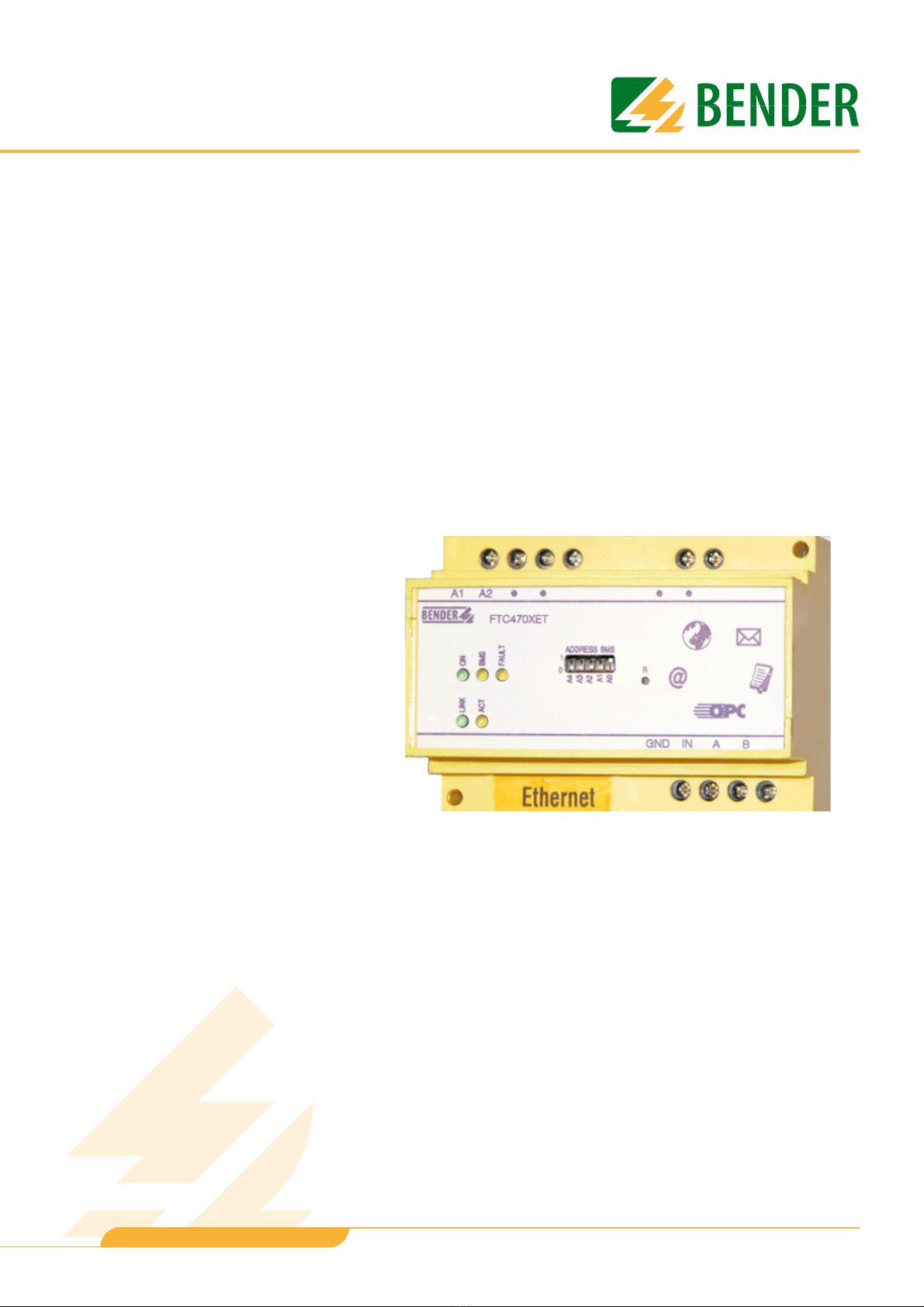
FTC470XET
Protocol converter for the connection of the
Bender measuring interface to the
TCP/IP network via Ethernet
Software version D177 V2.3x
TGH1375en/02.2010

©Dipl.-Ing. W. Bender GmbH & Co. KG
All rights reserved.
Reprinting only with permission
of the publisher.
Subject to change!
Dipl.-Ing. W. Bender GmbH & Co. KG
Londorfer Str. 65 • 35305 Grünberg • Germany
Postfach 1161 • 35301 Grünberg • Germany
Tel.: +49 6401 807-0
Fax: +49 6401 807-259
E-mail: [email protected]
Web server: http://www.bender-de.com

3
Table of Contents
TGH1375en/02.2010
1. How to use this documentation effectively ....................................................... 7
1.1 How to use this manual ......................................................................................................... 7
1.2 Chapters at a glance ............................................................................................................... 7
1.3 Quick reference guide ............................................................................................................ 8
2. Safety instructions .................................................................................................. 9
2.1 Work activities on electrical installations ........................................................................ 9
2.2 Address setting ......................................................................................................................... 9
3. Bus coupling .......................................................................................................... 11
3.1 Minimal system ...................................................................................................................... 11
3.2 Standard application ........................................................................................................... 12
3.3 Restrictions .............................................................................................................................. 12
4. The FTC470XET protocol converter .................................................................. 13
4.1 Scope of delivery ................................................................................................................... 13
4.2 Features .................................................................................................................................... 13
4.3 Display and operating elements ..................................................................................... 14
4.3.1 LED status indication ........................................................................................................... 14
4.3.2 Address-DIP switch and Reset micro pushbutton .................................................... 15
4.4 BMS side of the FTC470XET ............................................................................................... 16
4.4.1 Alarm and operating messages ....................................................................................... 16
4.4.2 Diagnostics and parameterisation .................................................................................. 16
4.4.3 Redundant master function .............................................................................................. 16
4.4.4 FTC470XET in slave mode .................................................................................................. 16
4.5 Ethernet side of the FTC470XET ...................................................................................... 17
4.5.1 Communication between Ethernet/TCP/IP interface and the BMS bus ........... 17
4.6 Intended use ........................................................................................................................... 17
5. Installation ............................................................................................................. 19
5.1 Basic configuration ............................................................................................................... 19
5.1.1 Preparations ............................................................................................................................ 19
5.1.2 Setting the BMS address ....................................................................................................19

Table of Contents
4TGH1375en/02.2010
5.1.3 Adapting a single PC to the network parameters of the FTC470XET ................. 20
5.1.4 Setting the IP address and network mask of the FTC470XET ................................ 21
5.1.5 Resetting the network parameters to factory setting .............................................. 22
5.2 Mounting and connection of the device ...................................................................... 23
5.2.1 Wiring diagram ....................................................................................................................... 24
6. The user interface of the internal Web server ................................................ 25
6.1 Web browser ........................................................................................................................... 25
6.2 User interface structure ....................................................................................................... 27
6.3 The BMS explorer ................................................................................................................... 28
6.3.1 Operation of the BMS explorer ......................................................................................... 28
6.3.2 Three level hierarchically granted access rights with password protection .... 28
6.3.3 Standard menu, not password-protected .................................................................... 30
6.3.4 Submenu for the parameterisation of FTC470XET, password-protected ......... 31
6.4 The monitoring and parameterisation frame .............................................................. 32
6.4.1 Calling up the menus and submenus ............................................................................ 32
6.4.2 Alarms and prewarnings highlighted in colours ........................................................ 32
6.4.3 Input devices ........................................................................................................................... 33
6.4.4 Sequence of the menu item description ...................................................................... 33
6.5 Main menu functions ........................................................................................................... 34
6.5.1 The start page ......................................................................................................................... 34
6.5.2 Language selection for the user interface .................................................................... 34
6.5.3 Password for parameter setting ....................................................................................... 34
6.5.4 System overview .................................................................................................................... 34
6.5.5 Current alarm messages ...................................................................................................... 34
6.5.6 History memory ...................................................................................................................... 35
6.5.7 Data logger .............................................................................................................................. 35
6.5.8 Activating previously configured Intranet/Internet or e-mail addresses
(optional) .................................................................................................................................. 36
6.6 The functions of the FTC470XET submenu .................................................................. 37
6.6.1 Device information query ...................................................................................................37
6.6.2 System description query ...................................................................................................37
6.6.3 System logger query ............................................................................................................ 37
6.6.4 Device parameter setting ...................................................................................................37
6.6.5 Entering system description .............................................................................................. 37
6.6.6 Data logger setting ............................................................................................................... 38
6.6.7 History memory setting ....................................................................................................... 38
6.6.8 System logger setting .......................................................................................................... 38
6.6.9 Device monitoring setting ................................................................................................. 39
6.6.10 Translation of previously used terms into any target language ........................... 39
6.6.11 Storing two addresses in Internet format (enter URL for Links) ........................... 40

Table of Contents
5
TGH1375en/02.2010
6.6.12 Network parameter setting ............................................................................................... 41
6.6.13 E-mail parameter setting for notification in case of alarm. .................................... 42
6.6.14 Sending a test mail ............................................................................................................... 44
6.6.15 Changing the password .....................................................................................................44
6.6.16 System software update ..................................................................................................... 44
7. Web server application examples ..................................................................... 45
7.1 Monitoring of an RCMS470-12 connected to the BMS bus ................................... 45
7.1.1 Calculating actual measured values .............................................................................. 46
7.1.2 Retrieving device information .......................................................................................... 46
7.1.3 Displaying collected data logger information in Excel ........................................... 47
7.2 Parameter setting of an RCMS470-12 connected to the BMS bus ...................... 48
7.2.1 Disabling a measuring input ............................................................................................. 48
7.2.2 Monitoring an N conductor for undercurrent ............................................................ 49
7.2.3 CT connection monitoring parameter setting ........................................................... 49
7.2.4 Setting a CT correction factor ........................................................................................... 50
7.2.5 Discriminator circuit with RCMS470-12 (Monitoring a "window") ...................... 51
7.2.6 Changing an alarm text or a measuring point description .................................... 52
7.3 Monitoring an IRDH275B connected to the BMS bus .............................................. 53
7.4 Parameter setting for an IRDH275B connected to the BMS bus .......................... 54
7.4.1 Setting the parameters for response values, operating principle
of the relays and starting time of the automatic self test ...................................... 55
8. Application of the internal OPC server ............................................................ 57
8.1 Function ................................................................................................................................... 57
8.1.1 OPC specification .................................................................................................................. 57
8.1.2 OPC data structure ............................................................................................................... 57
8.2 OPC compatibility with Windows 2000 or Windows XP ......................................... 58
8.3 Displaying BMS data using the OPC Demo Client .................................................... 63
8.3.1 Starting the OPC client and carrying out a connection to the OPC server ...... 63
8.3.2 Data collection of the whole BMS system via BMS addresses
and channels .......................................................................................................................... 64
8.3.3 Compilation of the BMS addresses being monitored, BMS channels
and items ................................................................................................................................. 65
8.3.4 Monitoring of the compiled BMS addresses, BMS channels and items ............ 66
8.4 Channels, data types and data values of BMS devices ............................................ 67
8.4.1 Alarm messages ..................................................................................................................... 67
8.4.2 Operating messages ............................................................................................................ 70

Table of Contents
6TGH1375en/02.2010
9. How to use the FTP server .................................................................................. 71
9.1 System software update ..................................................................................................... 71
9.2 Backup of specific system files .......................................................................................... 71
10. Service and support ........................................................................................... 73
10.1 Damage in transit .................................................................................................................. 73
10.2 Malfunctions ............................................................................................................................ 73
10.2.1 What should be checked? .................................................................................................. 73
10.2.2 Where do you get help? ...................................................................................................... 73
10.3 Warranty claims ...................................................................................................................... 73
10.4 Warranty and liability ........................................................................................................... 74
11. Technical data ..................................................................................................... 75
11.1 Data in tabular form .............................................................................................................. 75
11.2 Dimension diagram .............................................................................................................. 76
11.3 Ordering information ........................................................................................................... 77
12. Frequently asked questions: ............................................................................ 79
INDEX ...........................................................................................................................81

7
TGH1375en/02.2010
1. How to use this documentation effectively
1.1 How to use this manual
This operating manual will concern qualified experts in electrical engineering and communica-
tion technology!
In order to make it easier for you to find specific text passages or references in this manual
and for reasons of comprehensibility, important information is emphasised by symbols. The
meaning of these symbols is explained below:
1.2 Chapters at a glance
zHow to use this documentation effectively
This chapter provides tips and useful information on how to use this manual.
zSafety instructions
This chapter describes the dangers during installation and when operating the device.
zBus coupling:
This chapter deals with the normal use of this product.
zThe protocol converter FTC470XET (gateway):
This chapter describes the scope of delivery, the operating and display elements available at the
device, the function of the protocol converter as well as the intended use.
zInstallation:
This chapter describes the device settings required to be set prior to installation and the installation
itself.
zThe user interface of the Web server:
This chapter describes the user interface intended to be used to check and parameterise the proto-
col converter FTC470XET and a BMS system connected to it.
zApplication examples for the Web server:
This chapter provides examples intended to facilitate the operation of the FTC470XET.
zUse of the internal OPC server:
This chapter describes the OPC server function and its use with the help of the demo client.
Information calling attention to hazards are marked with this warning symbol.
Information intended to assist the user to make optimum use of the product are
marked with the Info symbol.

How to use this documentation effectively
8TGH1375en/02.2010
zUse of the FTP server:
This chapter describes the use of the internal FTP server in the example of FTC470XET system file
updates.
zService and support:
This chapter offers service and support in case of malfunction. In addition, this chapter provides
information about the technical sales department.
zTechnical data:
This chapter provides an overview of technical data, a dimension diagram and ordering details.
zFrequently asked questions:
This chapter provides a list of answers to many common questions. This list will possibly help you to
get all basic problems solved.
1.3 Quick reference guide
If you are familiar with networking, particularly with Ethernet, it may be helpful to start right
away with "chapter 4. The FTC470XET protocol converter" and "chapter 5. Installation". In
chapter 4 you will find information about display and operating elements as well as interfac-
es. Chapter 5 provides information about the basic configuration, installation and the con-
nection of FTC470XET.

9
TGH1375en/02.2010
2. Safety instructions
2.1 Work activities on electrical installations
zAll work activities necessary for installation, commissioning or work activities during operation of
electrical devices or systems are to be carried out by adequately skilled personnel.
zObserve the relevant regulations applying to work on electrical installations, in particular
EN 50110 or its subsequent regulation.
zIf the equipment is used outside the Federal Republic of Germany, the respective national standards
and regulations are to be observed. The European standard EN 50110 is recommended to be used as
a directive.
2.2 Address setting
A prerequisite for proper functioning of the FTC470XET protocol converter is its correct ad-
dress setting.
Ensure correct address setting at the FTC470XET. For details refer to the chapter basic con-
figuration beginning with page 19.
Unprofessional work activities on electrical installations may result in a
threat of danger to the life and health of human beings!
Assigning addresses that are already used by existing devices in the BMS or TCP/IP
network concerned may cause serious malfunctions.

11
TGH1375en/02.2010
3. Bus coupling
BENDER devices with bus interface communicate with each other via the Bender measuring
device interface (BMS bus). The FTC470XET allows data exchange between the BMS bus and
TCP/IP based networks via Ethernet.
This protocol converter enables you to query and parameterise Bender devices connected to
the BMS bus or single user PCs via Internet or local computer networks.
3.1 Minimal system
At least, the following components are required to operate an FTC470XET:
zA network-capable computer with Ethernet connection and a frame-capable Web browser. The
FTC470XET user interface has been optimised for displays with a resolution of 1024 x 768 pixels.
zAn Ethernet connection with a cross over patch cable, STP,
RJ45 plug.
zSuitable IP addresses for communication between the computer and the FTC470XET. Both devices
must have IP addresses of the same address range and identical network masks.
Fig. 3.1: Minimal system to operate an FTC470XET
120 W
A B
max. 1200 m
BA
120 W
FTC470XET
Bender measuring device interface (BMS bus)
TCP/IP via Ethernet
Web
browser
RJ45 Cross over
Web server
10 Mbit/s
BMS
RS485
OPC server
FTP server

Bus coupling
12 TGH1375en/02.2010
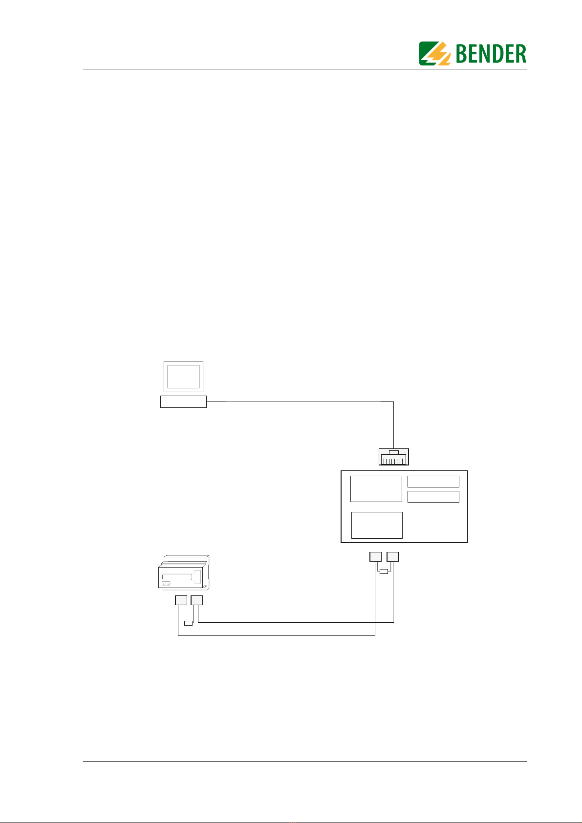
3.2 Standard application
In order to use BMS data, connect the internal FTC470XET Web server via the Ethernet/TCP/
IP interface to the local TCP/IP network (LAN), for example. Then the internal Web server
can be queried and parameterised with frame-capable Web browsers. The diagram below
shows how to access BMS devices via Internet and from a local network.
Fig. 3.2: Block diagram of a BMS bus and Ethernet coupling
3.3 Restrictions
Bender devices, such as TM panels or PRC1470, use in addition to the internal interface an
external BMS interface capable of connecting the devices to extended external BMS net-
works. This external interface cannot be addressed by the FTC470XET .
TM operator panels or PRC1470 in BMS networks only can communicate with the
FTC470XET via their internal interface, parameter setting is not possible!
120 W
A B A B A B
max. 1200 m
BA
120 W
FTC470XET
Bender measuring device interface (BMS bus)
TCP/IP via Ethernet
LAN 1
Web
browser
Internet
Firewall
PC1 PC2 PC3
LAN 2
RJ45
Web server
Web
browser
TCP/IP via ISDN DSL ...
10 Mbit/s
BMS
RS485
OPC server
FTP server

13
TGH1375en/02.2010
4. The FTC470XET protocol converter
This chapter describes
zthe scope of delivery
zthe features
zthe operating and display elements of the device
zthe function of the protocol converter (gateways)
zthe intended use
4.1 Scope of delivery
Included are:
zthe FTC470XET protocol converter
zthe operating manual
4.2 Features
A compact design has been realised for the Web server implemented for test, service and
parameterisation purposes. Its capacity therefore is restricted.
zCompact Web server for test, service and parameterisation purposes
with restricted functionality.
zConnects TCP/IP networks to the BMS bus via Ethernet:
hardware solution with firmware, no additional special software required.
zInternal Web server for the provision of all the BMS data, retrievable via frame-capable
Web browsers, optimised for a monitor resolution of 1024 x 768 pixels.
zThree-plus-one-language user interface:
English, German, French and one operator-settable language.
zAutomatic recognition of all addresses existing on the BMS bus.
zChannel-related indication of the currently measured values of each BMS device:
Alarm, operating and status messages.
zDisplay of the system characteristics of the respective BMS device,
e.g. measuring point description, alarm texts designed as required.
zParameterisation of the devices on the BMS bus.
zStorage and display of the alarm messages in the history memory :
Memory for up to 600 data records.
zLog function for measured values:
20 Data loggers for up to 600 records each.
zE-mail notification in case of alarms and system faults.
zHierarchically granted access rights with password protection.
zOPC server for communication with visualisation software of building control systems.
zFTP server for easy system software update.
zRemote maintenance via Internet possible.
The FTC470XET protocol converter
14 TGH1375en/02.2010
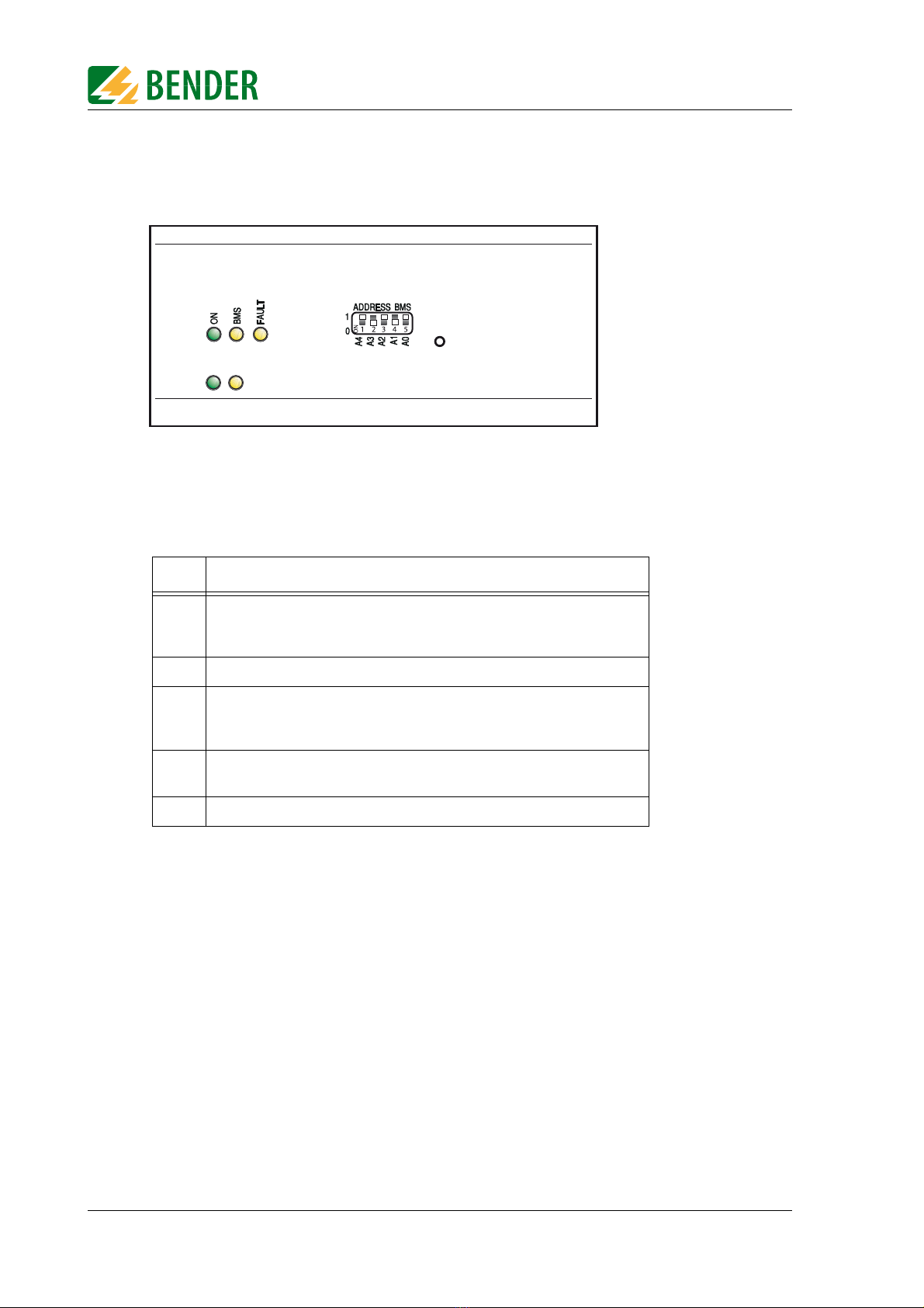
4.3 Display and operating elements
Fig. 4.1: FTC470XET front plate
4.3.1 LED status indication
LED Meaning:
ON
Green Power ON LED lights permanently in case of correct power supply
and when the device is ready for operation.
Green LED flashes during the Web server start.
BMS Yellow BMS LED signals activity on the BMS bus.
FAULT
Yellow FAULT LED lights in case of disturbances on the BMS bus, when an
unvalid BMS address has been set and/or in case of FTC470XET
malfunctions or when there is no master on the BMS bus.
LINK Green LED lights permanently when there is a connection to the next Eth-
ernet node (hub, switch, router, PC, etc.).
ACT Yellow LED signals TCP/IP data traffic.
ACT
LINK
R
FTC470XET

The FTC470XET protocol converter
15
TGH1375en/02.2010
4.3.2 Address-DIP switch and Reset micro pushbutton
The DIP switch is intended for binary BMS bus address assignment: 1-30 (1 = Master mode)
Tab. 4.1: Table of permissible BMS addresses
A restart can be carried out using the micro pushbutton located at the rear of the front plate
(hardware reset).
The BMS addresses 0 and 31 are not permitted to be set!
Dec.
addr. A4 A3 A2 A1 A0 Dec.
addr. A4 A3 A2 A1 A0
1 00001 16 10000
2 00010 17 10001
3 00011 18 10010
4 00100 19 10011
5 00101 20 10100
6 00110 21 10101
7 00111 22 10110
8 01000 23 10111
9 01001 24 11000
10 01010 25 11001
11 01011 26 11010
12 01100 27 11011
13 01101 28 11100
14 01110 29 11101
15 01111 30 11110
A4 A3 A2 A1 A0
ADDRESS BMS
1
0

The FTC470XET protocol converter
16 TGH1375en/02.2010
4.4 BMS side of the FTC470XET
On the BMS side, the FTC470XET protocol converter can optionally be used as master or as
slave.
zBMS address 1 = master mode
zBMS address 2 to 30 = redundant master mode
zBMS address 2 to 30 = slave mode
The following data types are available on the BMS bus:
4.4.1 Alarm and operating messages
Bender devices connected to the BMS bus are cyclically scanned for alarm and operating
messages. Each device can store up to 12 alarm and operating messages, which are organised
according to the channels 1-12.
4.4.2 Diagnostics and parameterisation
This data is only sent to the bus if requested by BMS commands.
4.4.3 Redundant master function
FTC470XET provides the "Redundant master" function. In the event of failure of the regular
master (bus address 1) after approximately 60 seconds this "Redundant master" takes over
the master function in order to control the BMS bus. If the regular master becomes active
again, the "redundant" FTC470XET returns the master function.
In case of failure of the regular master, first the device with BMS address 2 tries to become
redundant master. If it fails to take over the master function, address 3 will be the next and
so on. That means that an FTC470XET with BMS address 2 is more likely to take over the
redundant master function than a device with address 30.
4.4.4 FTC470XET in slave mode
If the FTC470XET is operated in the slave mode in the existing BMS environment, one of the
following devices has to act as BMS master:
zIRDH275, 375, 575 software version 1.40 or higher
zPRC1470 software version 1.82 or higher
zTM1000 software version 1.82 or higher
zFTC470XDP software version 1.31 or higher
zFTC470XET software version 1.01 or higher
zFTC470XMB software version 1.31 or higher
It is recommended to prefer the master mode in order to get faster data access.
The FTC470XET provides the redundant master function when a BMS address be-
tween 2 and 30 has been assigned to it.
Please note that the FTC470XET cannot be operated in combination with a PRC470
control and indicating device!

The FTC470XET protocol converter
17
TGH1375en/02.2010
4.5 Ethernet side of the FTC470XET
4.5.1 Communication between Ethernet/TCP/IP interface and the BMS bus
On the Ethernet side of the protocol converter various data and services are available.
zInternal Web server:
– Representation and parameterisation of BMS data and functions is possible with frame-capable
Web browsers.
– The entire data is represented by means of HTML4.0 and JavaScript 1.0.
zInternal Email client:
– E-mail notification in case of alarms and system faults.
zInternal OPC server
– Provision of alarm and operating messages for the standardised OPC interface according to the
specification: Data Access 2.0
zInternal FTP server
– System software update by means of FTP data transfer.
– Backup of the system software by means of FTP data transfer.
The Ethernet interface does not require any configuration. The TCP/IP protocol carried out
via this interface, however, requires an IP address. Details about address assignment are dis-
cribed in chapter "Basic configuration" on page 19.
4.6 Intended use
The FTC470XET protocol converter connects the serial Bender BMS bus to a TCP/IP network
via Ethernet. The converter is capable of transmitting data from the BMS bus to the TCP/IP
network and vice versa.
The FTC470XET provides information from the BMS network via one internal Web browser
and OPC server.
Communication with the Web server is carried out via a frame-capable Web browser. The
user interface has been optimised for a resolution of 1024 x 768 pixels.
Interface on the Ethernet side:
Interface on the BMS side:
The FTC470XET can optionally be operated as master or slave.
For communication, the FTC470XET always requires a TCP/IP address.
Generally, the FTC470XET is to be operated as master on the BMS side
(BMS address 1). This is the standard setting to achieve higher data throughput.


19
TGH1375en/02.2010
5. Installation
5.1 Basic configuration
5.1.1 Preparations
First consult the person in charge of the electrical installation for the addresses and net masks
of the protocol converter in the respective bus structures (BMS and TCP/IP). It is also nec-
essary to find out whether the FTC470XET can be operated as BMS master (default setting
for higher data throughput).
Prior to installation and connection, an address has to be assigned to the FTC470XET. What
you need is:
zA free BMS address between 2 and 30 for FTC470XET or a permission to assign the master function to
the device, that means, BMS address 1 is assigned to the FTC470XET.
zA free IP address and the net mask for the FTC470XET connection to the local network intended to
be used, subnetting is possible.
zOptional:
The IP address of the default gateways, DNS server, and WINS server
zA cross-over-patch cable and a straight-through-patch cable (LAN cable).
A cross-over-patch cable can be distinguished from a straight-through-patch cable by the wiring of
the transparent RJ45 plugs. The sequence of colours of the parallel conductors is different.
zA PC or Laptop which at least can be operated temporarily separately from the computer network.
5.1.2 Setting the BMS address
1. If it is possible from the technical point of view to assign the master function on the BMS bus to the
FTC470XET, BMS address 1 must be used. The device will already be delivered with this factory set-
ting.
2. Otherwise set the appropriate BMS address (2 to 30, see page 15) by means of the DIP switch accord-
ing to the binary system. By way of example, address 5 corresponds to the switch positions:
A4=0 A3=0 A2=1 A1=0 A0=1
Factory setting = 1 (BMS master)
If you are familiar with the configuration of computer networks, you can carry out
the connection of the FTC470XET by yourself. Otherwise please contact your EDP
administrator!
Assigning addresses that are already used by existing devices on the BMS or TCP/IP
network can cause serious malfunctions.

Installation
20 TGH1375en/02.2010
5.1.3 Adapting a single PC to the network parameters of the FTC470XET
In order to address a protocol converter, the network data of your single PC have to be adapt-
ed temporarily to the network data of the FTC470XET.
Factory setting of the FTC470XET:
IP address 192.168.0.254
net mask 255.255.255.0
For changing the default network parameters of your single PC: (e.g. with Windows 2000)
proceed as follows:
1. Connect the PC to the FTC470XET with a cross-over-patch LAN cable.
2. Now open the start page using the path Start/Settings/Network and DFÜ connections. There dou-
ble-click (your) LAN connection.
The "Status of LAN connections" screen appears.
3. Click "Properties".The "Properties of LAN connection" screen appears.
4. Double-click "Internet protocol (TCP/IP)“.
The window "Properties of the Internet protocol" appears.
5. Enter the IP address in the associated edit field:
192.168.0.200
Use the TAB key or the mouse, if required, in order to go the next enter position.
Usually, the associated network mask appears automatically. If not, enter the IP address manually:
255.255.255.0
Table of contents
Other Bender Media Converter manuals


