Problem Possible Cause Solution
The air conditioning does
not attempt to turn on.
The compressor timer
lockout may prevent the air
conditioner from turning on
for a period of time
Adjust the Compressor Min.
Off Time to “None”.
The display is blank. Lack of proper power. Make sure the power is on
to the furnace and that you
have a 24vac between R&C.
The air conditioning does
not attempt to turn on.
The cooling setpoint is set
too high.
Lower the cooling setpoint
or lower the cooling
setpoint limit.
The heating does not
attempt to turn on.
The heating setpoint is set
too low.
Raise the heating setpoint
or raise the heating
setpoint limit.
When using a residential
heat pump the heat
comes on instead of the air
conditioning.
The thermostat reversing
valve dip switch is set
incorrectly.
Set the reversing valve dip
switch to ‘O’.
When calling for air
conditioning both the heat
and cool come on.
The thermostat equipment
dip switch is configured for
“HP” and the HVAC unit is a
gas/electric.
Set the equipment dip
switch for “gas”.
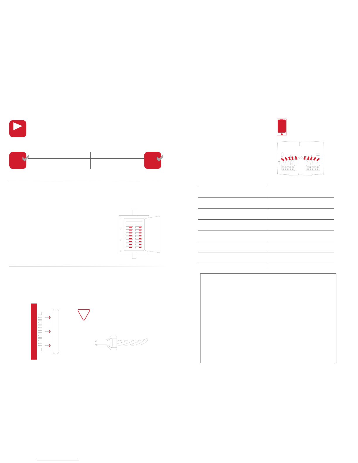
Step 7 Attach Thermostat Display
1) Align the pins on the display with the corresponding holes below the
wiring connectors and push the top and the bottom of the display until it
clicks into place.
First Alert® Onelink® Limited Warranty
Troubleshooting
Use the following troubleshooting guide to diagnose common
problems. If you are still having problems or are unsure please
visit firstalertthermostats.com, call 800-323-9005.
Step 9 Set Up Thermostat
1) Follow the on-screen instructions to join your household wireless
network and setup your thermostat.
2) Visit Firstalert.skyportcloud.com from your personal computer to
create an account and access your thermostat remotely for control
away from the home.
Step 8 Switch Breakers Back On
Turn your furnace and A/C breakers back on at your household breaker panel.
Display should click into place easily.
If you encounter resistance do not
apply excess force – take the plate
off, check that the pins are straight
and ensure there are no wires in the
way and retry.
!
Side View
TIP: Download the First Alert® Onelink®
Thermostat app to your mobile device(s)
NOTE: Your skyport username and login is
the same you used to set up the app.
PRODUCT LIMITED WARRANTY
BRK Brands, Inc., (“BRK”) the maker of Onelink™ and First Alert® brand products warrants that for a period of one year from the date of purchase (the “Warranty Period”), this product will be free from defects in
material and workmanship. BRK, at its sole option, will repair or replace this product or any component of the product found to be defective during the Warranty Period. Replacement or repair will be made with a new or
remanufactured product or component. If the product is no longer available, replacement may be made with a similar product of equal or greater value. This is your exclusive warranty. This warranty is valid for the original
retail purchaser only from the date of initial retail purchase and is not transferable. In order to obtain warranty service, you must keep the original sales receipt and proof of purchase in the form of the UPC code from the
package. BRK dealers, service centers, or retail stores selling BRK products do not have the right to alter, modify or any way change the terms and conditions of this warranty.
WARRANTY EXCLUSIONS
Parts and Labor: 1 year limited (warranted parts do not include bulbs, LEDs, and batteries) This warranty does not apply to bulbs, LEDs, and batteries supplied with or forming part of the product. This warranty is invalidated
if non- BRK accessories are or have been used in or in connection with the product or in any modification or repair is made to the product. This warranty does not apply to defects or damages arising by use of the product in
other than normal (including normal atmospheric, moisture and humidity) conditions or by installation or use of the product other than in strict accordance with the instructions contained in the product owner’s manual. This
warranty does not apply to defects in or damages to the product caused by (i) negligent use of the product, (ii) misuse, abuse, neglect, alteration, repair or improper installation of the product, (iii) electrical short circuits or
transients, (iv) usage not in accordance with product installation, (v) use of replacement parts not supplied by BRK, (vi) improper product maintenance, or (vii) accident, fire, flood or other Acts of God. This warranty does not
cover the performance or functionality of any computer software included in the package with the product. BRK makes no warranty that the software provided with the product will function without interruption or otherwise
be free of anomalies, errors, or “Bugs.”This warranty does not cover any costs relating to removal or replacement of any product or software installed on your computer. BRK reserves the right to make changes in design
or to make additions to or improvements in its products without incurring any obligations to modify any product which has already been manufactured. BRK will make every effort to provide updates and fixes to its software
via its website. This warranty does not cover any alteration or damage to any other software that may be or may become resident on the users system as a result of installing the software provided. This warranty is in lieu
of other warranties, expressed or implied, and BRK neither assumes nor authorizes any person to assume for it any other obligation or liability in connection with the sale or service of the product. In no event shall BRK be
liable for any special or consequential damages arising from the use of the product or arising from the malfunctioning or non-functioning of the product, or for any delay in the performance of this warranty due to any cause
beyond its control. BRK does not make any claims or warranties of any kind whatsoever regarding the product’s potential, ability, or effectiveness to prevent, minimize, or in any way affect personal or property damage or
injury. BRK is not responsible for any personal damage, loss, or theft related to the product or to its use for any harm, whether physical or mental related thereto. Any and all claims or statements, whether written or verbal,
by salespeople, retailers, dealers, or distributors to the contrary are not authorized by BRK, and do not affect this provision of this warranty. BRK’s responsibility under this, or any other warranty, implied or expressed, is
limited to repair, replacement or refund, as set forth above.These remedies are the sole and exclusive remedies for any breach of warranty. BRK is not responsible for direct, special, incidental, or consequential damages
resulting from any breach of warranty or under any other legal theory including but not limited to, loss profits, downtime, goodwill, damage to or replacement of equipment and property and any costs of recovering,
reprogramming or reproducing any program or data stored in or used with a system containing the product accompanying software. BRK does not warrant the software will operate with any other software except that
which is indicated. BRK cannot be responsible for characteristics of their party hardware or software which may effect the operation of the software included. Except to the extent prohibited by applicable law, any implied
warranty of merchantability or fitness for a particular purpose is limited in duration to the duration of the above Warranty Period. Some states, provinces, or jurisdictions do not allow the exclusion or limitation of incidental or
consequential damages or limitations on how long an implied warranty lasts, so the above limitations or exclusion may not apply to you. This warranty gives you specific legal rights, and you may also have other rights that
vary from state to state, or province to province, or jurisdiction to jurisdiction.
OBTAINING SERVICE
If service is required, do not return the product to your place of purchase. In order to obtain warranty service, contact the Consumer Affairs Division at 1-800-323-9005, 7:30 a.m. – 5:00 a.m. Central Standard Time,
Monday through Friday.To assist us in serving you, please have the model number and date of purchase available when calling.After contacting the Consumer Affairs Division and it is determined that the product should be
returned for Warranty Service, please mail the product to: BRK Brands, Inc., 3901 Liberty Street Road, Aurora, IL 60504-8122.
9 10