First Choice Metos MM-5 User manual
SPARE PARTS DIAGRAM FOR
First Choice Group
Blakeney Way, Kingswood Lakeside
Cannock, Staffs, WS11 8LD
TEL: 01543 577778 FAX: 01543504141
Email: [email protected]
Web: www.firstchoice-cs.co.uk
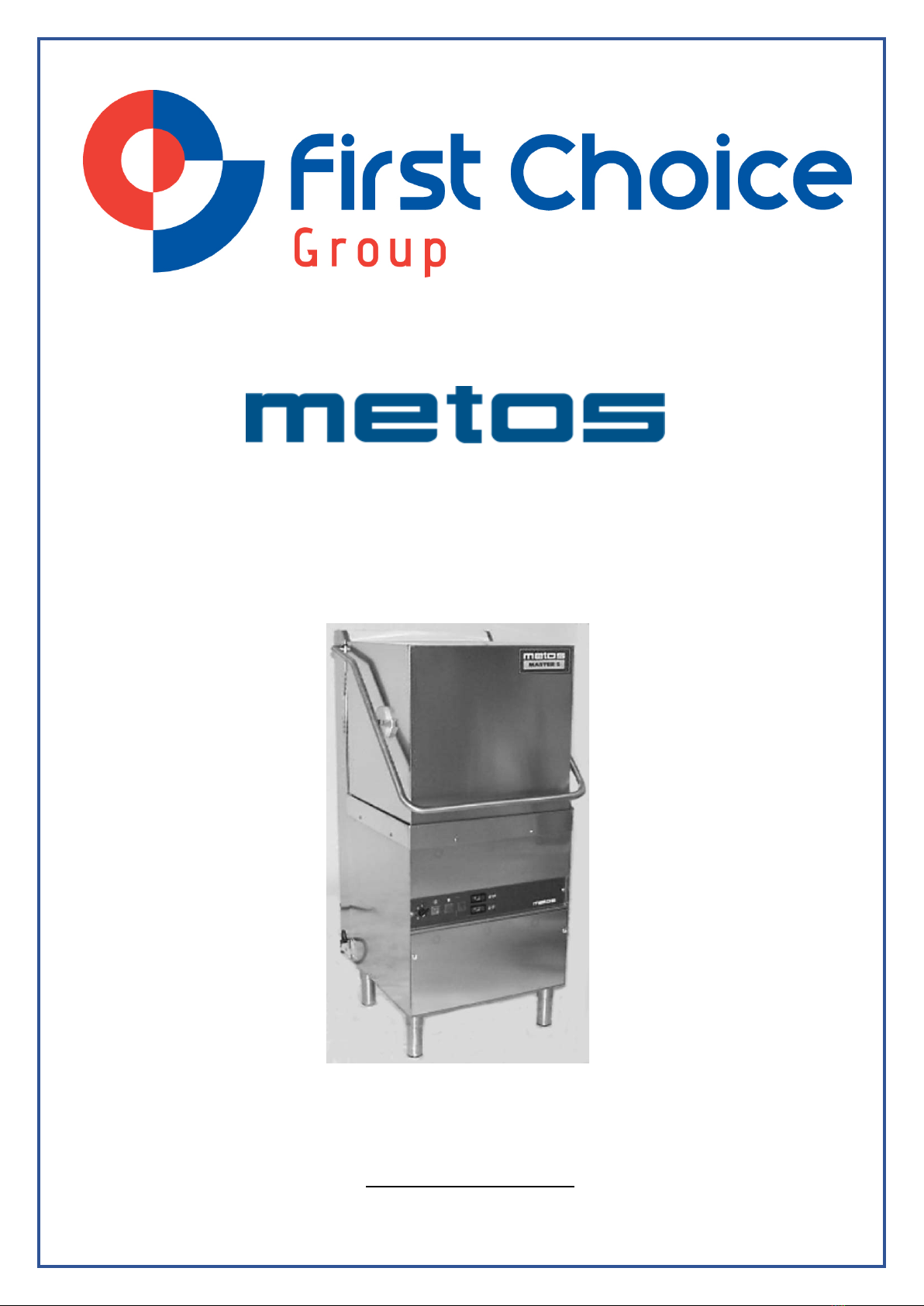
Dishwasher
MM-5 / MM-5A
(Valid from 2003)
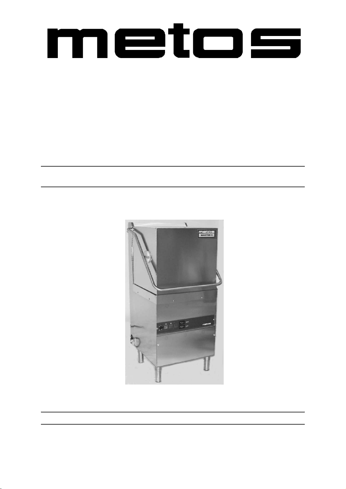
DISHWASHER
INSULATED MODEL
TYPE: MM5, MM5A
Accessories
BOOSTER PUMP
DRAIN PUMP
DETERGENT DISPENSER
Service Manual
S/N: Rev.: 2.4
25.3.2003 Rev. 2.4
Dear Customer,
Congratulations on deciding to choose a Metos equipment for your kitchen activities. You
made an excellent choice. We will do our best to make also you a satisfied Metos custom-
er like thousands and thousands of others all over the world.
Please read this manual carefully. You will learn many right, safe and efficient working
methods in order to get the best possible benefit from the equipment. The instructions and
hints in this manual will give you a quick and easy start in using this equipment. You will
note very quickly how nice it is to use the Metos equipment.
All rights are reserved for technical changes.
You will find all the main technical data on the rating plate fixed to the equipment. When
you need service or technical help, please let us know the serial number of the equipment.
This will make it easier to provide you with the correct service. Please write the contact
information of your local Metos service in advance on the lines below.
METOS TEAM
Metos service phone number:...............................................................................................
Contact person:....................................................................................................................

25.3.2003 Rev.
1. General .......................................................................................................... 1
1.1 Symbols used in the manual .......................................................................................... 1
1.2 Symbols used on the appliance ...................................................................................... 1
1.3 Checking the relation of the appliance and the manual ................................................. 1
2. Safety .............................................................................................................. 2
2.1 Safety instructions in case of malfunction ..................................................................... 2
2.2 Disposal of the appliance ............................................................................................... 2
2.3 Installation ..................................................................................................................... 2
2.4 Detergent and rinse aid .................................................................................................. 2
2.5 Washing and cleaning of the machine ........................................................................... 3
2.5.1 High pressure cleaning of the dishwasher ............................................................. 3
2.5.2 Inside of the machine ............................................................................................. 3
2.5.3 Outside of the machine .......................................................................................... 3
2.6 Floors ............................................................................................................................. 3
2.7 Repairs and maintenance of the machine ...................................................................... 3
3. Functional Description ................................................................................. 4
3.1 Application of the appliance .......................................................................................... 4
3.1.1 Prohibited use/Use for other purposes ................................................................... 4
3.2 Construction [MM5] ...................................................................................................... 4
3.2.1 Operating switches and signal lights ..................................................................... 5
4. Operation ....................................................................................................... 6
4.1 General .......................................................................................................................... 6
4.2 Operation procedures ..................................................................................................... 6
4.2.1 To fill with water [MM5] ....................................................................................... 6
4.2.2 Washing [MM5] .................................................................................................... 6
4.2.3 Hygiene warranty [MM5] ...................................................................................... 7
4.3 After operation ............................................................................................................... 7
4.3.1 Emptying, internal machine rinse [MM5] ............................................................. 7
5. Installation ..................................................................................................... 8
5.1 General .......................................................................................................................... 8
5.2 Operating conditions ..................................................................................................... 8
5.2.1 Lighting .................................................................................................................. 8
5.2.2 Ventilation ............................................................................................................. 8
5.3 Installation procedures ................................................................................................... 8
5.3.1 Electrical connections ............................................................................................ 8

25.3.2003 Rev.
5.3.2 Water connections [MM5] ..................................................................................... 8
5.3.3 Drain connection [MM5] ....................................................................................... 9
5.4 After installation ............................................................................................................ 9
5.4.1 First-run ............................................................................................................... 10
5.5 Staff training ................................................................................................................ 10
6. Adjustment instructions ............................................................................. 11
6.1 Setting the rinse aid dosing pump ............................................................................... 11
6.2 Setting the detergent dispenser [MM5] ....................................................................... 12
6.2.1 Control of the detergent dispensing ..................................................................... 12
6.3 Setting the temperatures [MM5] ................................................................................. 12
6.3.1 Energy saving in stand by period [E/S short circuit piece switched to ON position]
12
6.3.2 Temperature sensors [NTC] ................................................................................. 12
7. Service .......................................................................................................... 13
7.1 Service by authorized personnel .................................................................................. 13
7.1.1 Periodic service .................................................................................................... 13
7.1.2 Annual maintenance ............................................................................................ 13
7.1.3 Control circuit board function description [MM5] .............................................. 14
8. Troubleshooting .......................................................................................... 16
8.1 Temperature alarms [MM5] ........................................................................................ 16
8.2 Error alarms (the signal light of the wash cycle is blinking in the cycle) [MM5] ...... 17
9. Spare parts .................................................................................................. 19
9.1 Voltage codes .............................................................................................................. 21
9.2 Product codes ............................................................................................................... 21
10. Technical specifications ............................................................................ 35
This manual suits for next models
1
Table of contents


