First Degree Fluid E820 User manual
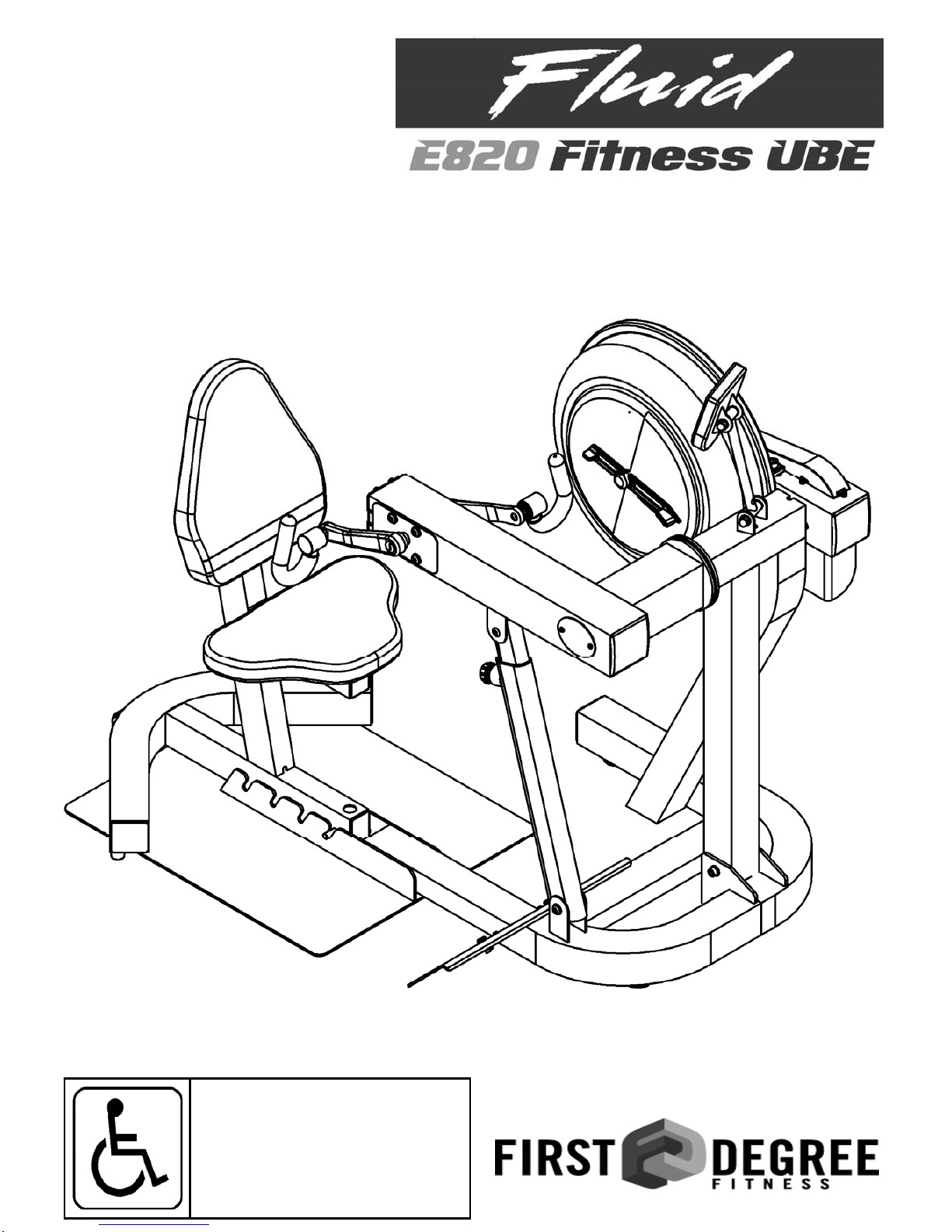
Owners Manual
Wheelchair Accessible

2
Contents
1. Contents of E820 Box.
2. E820 assembly instructions.
3. E820 Control arm.
4. Tank filling and water treatment.
5. Long term water treatment and basic operation.
6. The E820 Ergometer.
7. Maintenance/Troubleshooting.
8. Tank belt drive adjustment.
9. Parts list and Warranty.
Training with the E820
As with any piece of fitness equipment, consult a physician before beginning your
E820 exercise program.
CAUTION
Use two hands and follow all safety instructions whenever raising or lowering the
E820 control arm.
Warning
Do not remove hands while crank is in motion. The crank will continue to rotate and
could cause injury.

3
Hex Key
Telescoping tube
attachment bolts/
spring washers
Mainframe bolts Frame bolt washers
1x Multi-tool
Ix Seat Frame and
Baseplate Box Contents E820
1x Main frame with telescoping
tube and internal gas assist
1x Fill funnel/hose
3x Frame levelers
1x Handle
right
M10x25
x2 21x11x2
x4
M10x2
x2
Mainframe Nylock nut
4
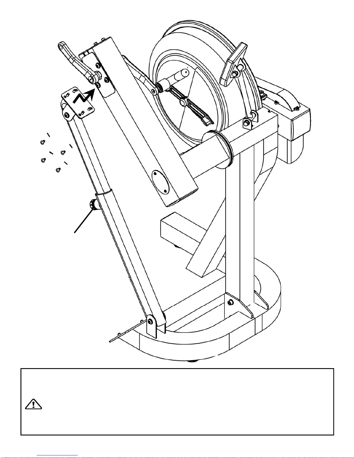
Step 1: Remove contents from box. Attach telescoping tube to the underside of the control
arm using 4x M8x15mm bolts and 4x M8 spring washers.
The control arm is heavy and may swing freely during this stage of
assembly. The Adjuster knob is pre-tightened from the factory in the
optimal position for assembly in relation to the control arm. Do not loosen the Adjuster
knob until the telescoping tube has been safely secured to the underside of the control arm.
CAUTION
E820 Assembly Instructions
4x 8x15mm bolts
and 4x M8 spring
washers
Adjuster knob

5
E820 Assembly instructions
M10 Nylock nut
Step 2: Attach base plate to lower
mainframe using 2x M10x25mm bolts,
2x M10 Nylock nuts and 4x 21x11x2
washers.
Step 3: Tilt the seat rearward until
transport wheel is engaged. Secure
the seat in any of the 4 adjustment
slots, or leave off entirely if wheelchair
access is required.
21x11x2 washer
M10x25mm bolt

6
E820 Assembly Instructions
Step 4: Secure right pedal onto Crank arm. The pedal threads have a blue coating which
will feel very tight when threaded onto the crank arm. This is a type of thread locker, and
once in contact with the crank arm threads will activate in approximately 15minutes.
Caution! Extreme over-tightening could damage the aluminum threads on the crank arm.
Note: Allow 15 minutes for the thread
locker to activate before first time use.
Check pedal tightness periodically
thereafter with a 15mm wrench.
7
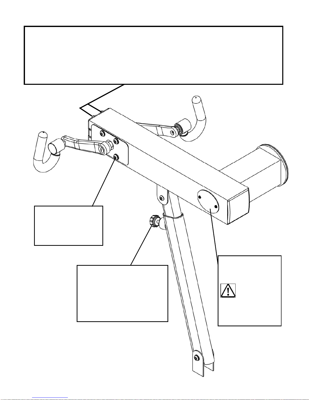
The E820 Control Arm
Chain tensioning bolts: Allows for tightening the chain or adjustment from side to side. Make sure
when tightening only to adjust the same amount for both bolts, otherwise the sprocket will be mis-
aligned.
Note: Tightening the right bolt only will pull the right side of the crank assembly toward you, tighten-
ing the left will pull the left side toward you. Use this feature to realign the rear with the front sprocket
if needed or when changing to a new chain.
Crank arm bolts:
Loosen all 8 bolts slightly
before adjusting/
tightening chain.
Inspection plate:
Open to check chain
tension.
Warning:
Do not check
chain tension
with fingers!
Adjuster Knob: Loosen to allow
the control arm to travel through
90 degrees of travel. Note the
telescoping tube is gas assisted.
Tighten securely when desired
workout position is reached.

8
Yellow
tank
plug
Filling hose and
funnel
Tank Filling and Water Treatment
Open the rear upper yellow
tank plug and insert hose
into tank (rotating the im-
peller slightly may be necessary to
allow the hose to pass), move the
tank adjuster handle to level 20
and begin filling. Do not fill the
tank higher than the level indicator
on the front of the clear shell. A
properly filled tank holds approxi-
mately 8liters of water.
Warning: Do not under any cir-
cumstances put fingers into the
tank. Use the end of the hose to
move the impeller should the need
arise.
Note: A large bucket is required for filling (Not included)
In areas where tap water quality is known to be poor, FDF recommends the use of distilled
water.
Water Treatment Proce-
dures:
1. Add Chlorine tablet.
2. Wait a minimum of 72
hours. Then add very small
amount of blue dye and
check for desired color. Im-
portant! Do not add blue
dye for at least 72 hours
following Chlorine treat-
ment. The blue dye adds
visual appeal as well as cut-
ting down the amount of light
affecting the tank water, thus
extending the amount of time
between water treatments.
Note: The blue
dye is extremely
concentrated and
will readily stain
carpet or clothing.
Caution: Use a drop cloth when filling
or adding blue dye
Blue Dye

9
Long Term Water Treatment and Basic Operation
Caution: It is important that a drop cloth be used under the fluid tank whenever the
tank plug is opened for water treatment.
The level of resistance is determined by the level indicator located on the front of the tank. Level
one indicates lightest resistance, level twenty represents heaviest resistance. Allow three to four
seconds after adjusting resistance handle for the correct resistance level to be achieved.
Long term water treatment:
Do not use any water treatment other than the tablets supplied with this machine. For re-
placement tablets, contact your local First Degree Fitness distributor.
Water treatment schedules for the E820 will vary according to the fluid tanks exposure to
sunlight, but expect 8-12 months near a bright, sunlit window and 2 years or more for a darker
location. At the point of finding the water slightly cloudy, add a Chlorine tablet. Remember to
wait 72 hours following the chlorine tablet before adding the blue dye as the Chlorine tablet is
extremely concentrated.
Important: Do not fill past the calibration mark as indicated on the tank level sticker or water
spillage may occur. See tank filling/water treatment page for details.
Resistance:
Use both hands when either raising or lowering the
E820control arm.
Removing hands before the crank comes to a com-
plete stop while training can cause injury. The crank
is direct drive so as to allow both forward and reverse
rotation during workouts.
Warning:
CAUTION
10
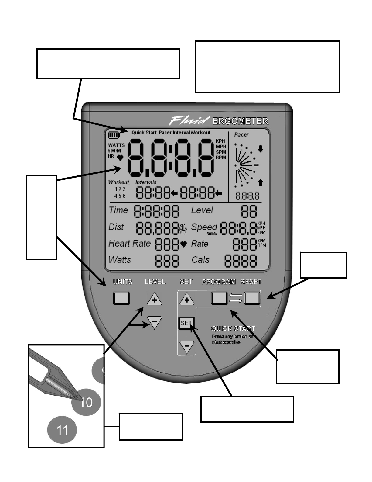
E820 Ergometer.
Quick start provides instant workout infor-
mation. Just start training to activate. You
can choose to change UNITS displayed.
UNITS
displays
WATTS,
RPM,
HR,
MPH,
KPH
Level Adjustable
from 1-20
Set Changes Time, Distance
parameters
Program Clears
current exercise
program
Note: For complete operational
instructions, please refer to the
computer manual, which is in-
cluded with your E820.
Reset
Clears data

11
Item Timeframe Instructions Notes
Seat and Frame. Weekly. Wipe down weekly with lint free
cloth or more often with heavy
club use.
PK belt tension. Monthly. Check monthly for signs of slip-
page. Adjust/tighten as required.
Tank and water
treatment. 12 months to 2 years. Follow instructions as specified
in the “Water Treatment” section
of this manual.
Chain drive. Check every 100 hours
for correct tension. Open the inspection plate and
check tension using a screw-
driver or other tool. Tighten as
required using chain tensioning
bolts located at the end of the
control arm.
E820 pedals. Tighten weekly using
15mm box wrench
(supplied)
The pedals should be checked
on a regular basis. A loose
pedal can cause damage to the
crank arm aluminum threads, re-
quiring replacement.
Maintenance Chart.

12
Fault Probable
Cause Solution
Water changes color or be-
comes cloudy. Rower is in direct
sunlight or has not
had water treatment.
Change rower location to reduce direct expo-
sure to sunlight. Add water treatment and
blue dye or change tank water as directed in
the water treatment section of this manual.
Knocking noise from inside
the control arm while train-
ing, especially when chang-
ing directions.
Chain requires tight-
ening or adjustment. Open inspection plate located on front of
control arm and check tension using a screw-
driver or other tool. Use the chain tensioning
bolts located at the rear of the control arm to
tighten or adjust as needed. The chain
should have approx 3mm of slack when prop-
erly adjusted. See P.7 for details.
Pedals slip during hard
training. PK tank belt requires
tightening. Remove large inspection plate next to the
tank, insert a long tool to push the rear end
cap out from the inside, exposing the tank
belt tensioning bolt. Loosen tank bolts
slightly. Remove upper rubber belt cover to
expose the PK belt. Tighten the tank tension-
ing bolt until the belt is too tight to be twisted
from side to side more than 45 degrees by
hand. See P.13 for details
Pedal is loose (either left or
right) and cannot be retight-
ened.
Aluminum crank arm
threads are stripped.
Contact service center for replacement. Then
check weekly as recommended.
Computer screen illumi-
nates, but does not register
when rowing.
Loose or failed con-
nection/Sensor gap
too wide (see erratic
computer display).
Check that the computer lead is connected
properly. If connected properly check sensor
gap. Contact your local service center if this
fails to address the problem.
The E820 computer does
not illuminate after battery
installation.
Batteries installed
incorrectly or need
replacing.
Reinstall batteries in correct position and try
again. If the LCD screen fails to illuminate,
try rotating the batteries slightly in the com-
puter. If this fails, contact your local service
center.
The E820 computer display
is erratic/slow while dis-
playing RPM and WATTS
Gap between sensor
and magnetic ring is
too wide.
Remove inspection plate and check sensor
gap and that magnetic ring is not wobbly.
Troubleshooting Guide:
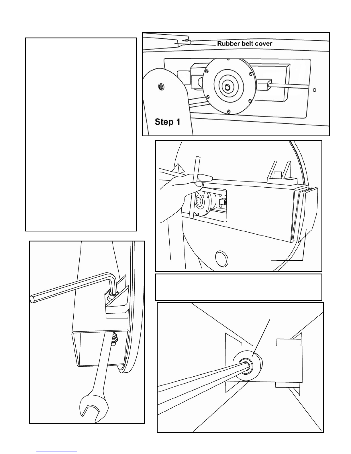
13
Step 1: Remove large metal inspec-
tion plate as shown above right.
Step 2: Using a long tool, push out
the rear end cap as pictured above
right. This will give you access to the
tank tensioning bolt (shown bottom
right).
Step 3: Loosen both the rear and
front tank bolts slightly as shown left.
Remove front rubber belt cover.
Step 4: Using a 6mm Allen key,
tighten the belt using the tank ten-
sioning bolt until the belt no longer
slips during hard rowing.
Note: Do not over tighten tank
bolts.
Step 3 Step 4
Tank tensioning bolt
Tank Belt Adjustment
Step 2 End Cap
Tip: Twist the belt by hand to gauge tightness. Correct
tension should be obtained when no longer able to twist
more than 60 degrees.
14
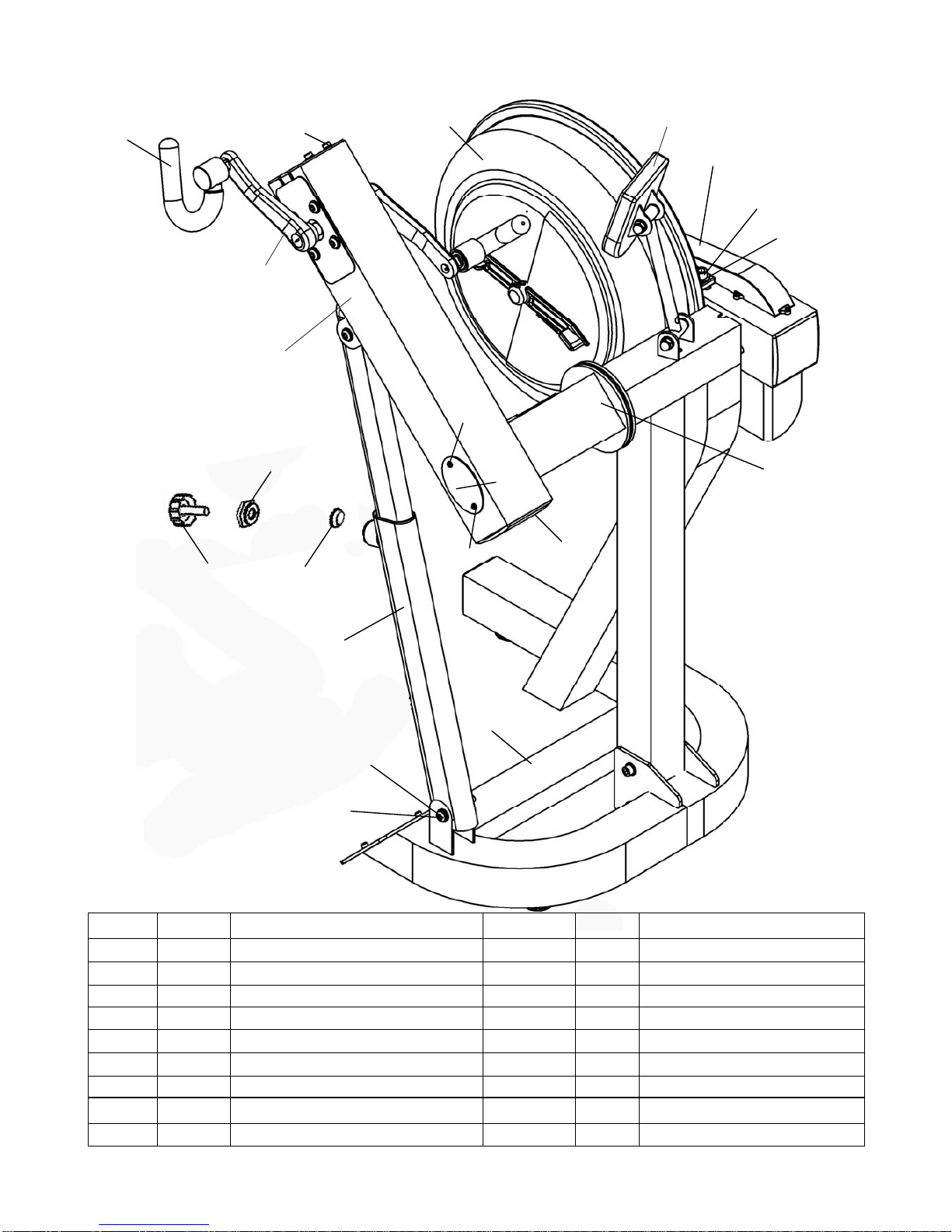
E820 Exploded Diagrams
12047 20850
10072
10070
10170
10066
23921
10067
Refer to Tank
Assembly
10043
10040
33100
33941
10096
10082
Refer to Control
Arm Assembly
Refer to Crank Arm
Assembly
Refer to Computer
Assembly
33937
33938
23144
P/N QTY Description P/N QTY Description
10040 1
Bolt M12x140 10170 6 Washer M4
10043 6
Washer M12 12047 1 Handle Complete
10066 3 End Cap 100x100mm 20850 1 Tension Adjustment
10067 2 Rubber Cover for Large PK Pulley 23144 1 Knob—Yellow M10 x 35
10070 18 Screw M4x10 23921 1 Control Arm Bushing
10072 2 Small Steel Side Cover 100mm 33100 1 Main Frame Assembly
10082 3
Washer M10 33937 1 Flange Nut M25
10096 1 Bolt M10x70 for Aluminum Rail 33938 1 Copper Locating Bushing
33941 1 Telescoping Tube External

15
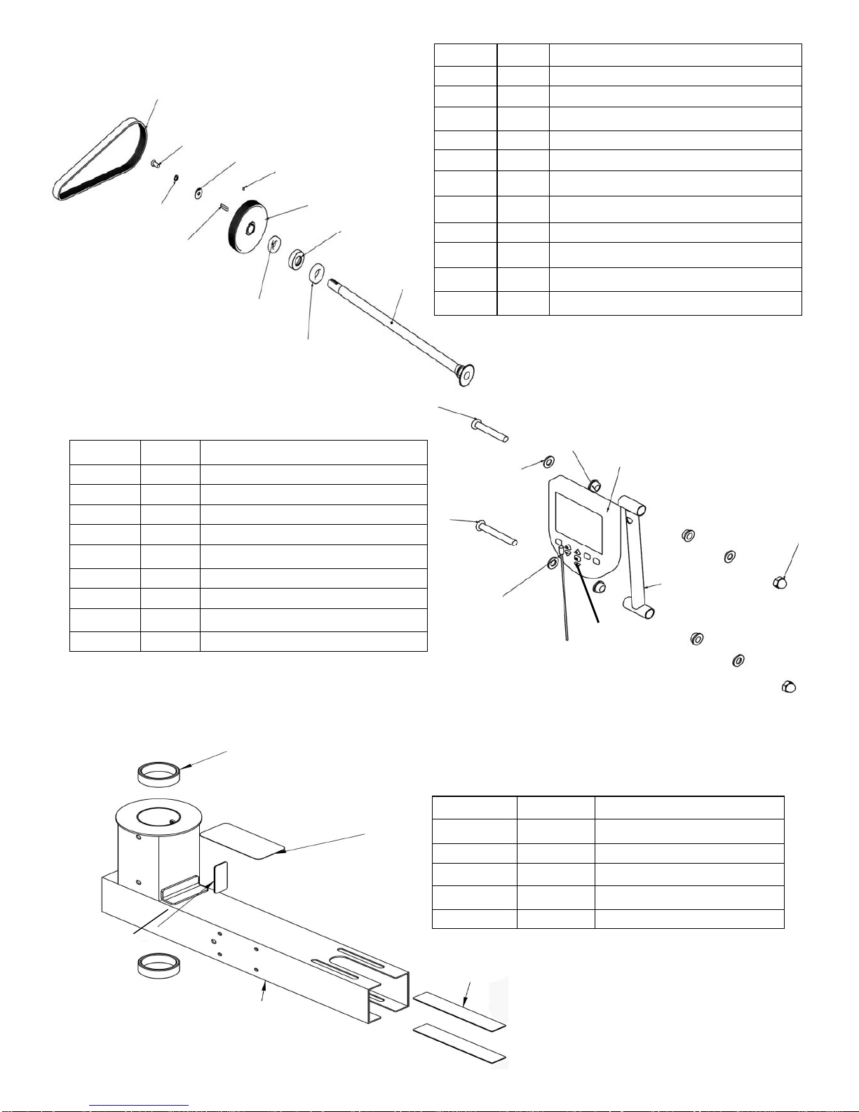
Seat Assembly
10081
10069
10120
20123
23008
10101
20009
10041 10082 10103
23501
10080
20115 20117
23700
P/N QTY Description
10041 1
Nut M10 Nylock
10069 2 End Cap 75x50mm
10080 8 Bolt M6x20
10081 8 Washer M6
10082 2
Washer M10
10101 2 Rubber Bumper
10103 2 Transport Wheel
10120 4 Bolt M6x15
23008 2 End Cap 75x75 Rubber
20009 1 Bolt M10x100
20115 1
Seat LS-622
20117 1 Seat Back LS-622
20123 4 Plastic Washer 30x6x12
23501 1 Seat Frame
23700 1 Foot Plate E820/920
16
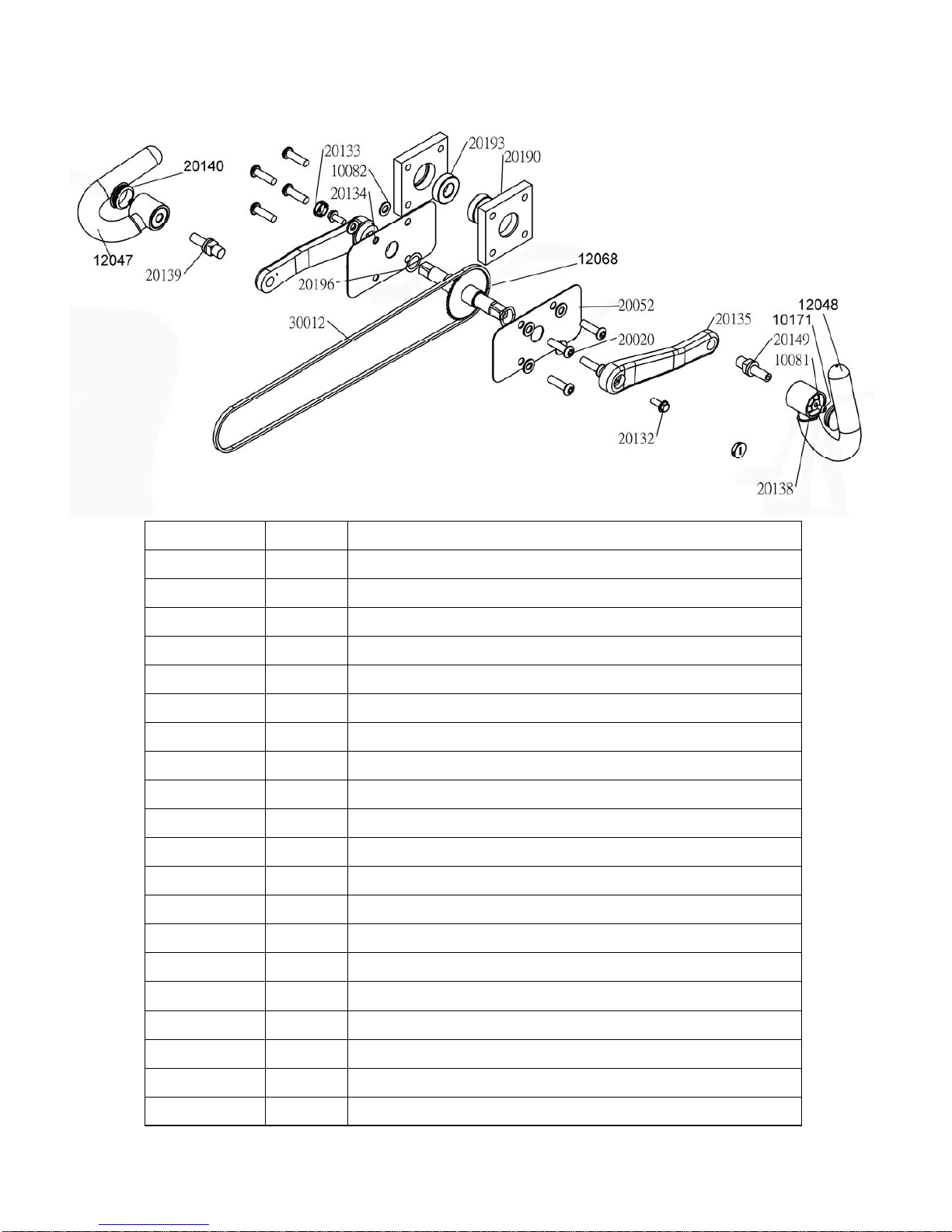
E820 Crank Arm Assembly
Part No. Qty Description
10081 2 Washer M6
10082 8 Washer M10
10171 2 Bolt M6x8
12047 2 Handle Complete
12048 2 Handle Grip
12068 1 Axle / Sprocket for E820
20020 8 Bolt M10x35
20052 2 Side Bearing Cover E720/820
20132 2 French Screw M8x20xP1.0
20133 2
Crank End Cap
20134 1 Crank-Left
20135 1 Crank-Right
20138 2 Bearing NSK6201ZZ
20139 1 Handle Shaft-Left
20140 1 End Cap 38
20149 1 Handle Shaft-Right
20190 2 Aluminum Block Bearing Housing
20193 2 NSK 6004ZZ Aluminum Block Housing Bearing
20196 2 Wave Washer 20mm
30012 1 DID-25 Chain 178
17
23920
20036
20170
20043
23291
10139
10017
10109
10011
10012
10015
10083
10146
10138
10052
Main Drive Assembly
Control Arm Assembly
P/N QTY Description
20036 1
Small Warning Decal
20043 1
Decal - UBE
20170 2 Chain Protection Decal
23291 1 Control Arm
23920 2 Control Arm Bushing
20157
P/N QTY Description
10011 1 Bearing Housing
10012 1 NSK 6005ZZ Bearing
10015 1 Large PK Transmission Pulley 150mm
10017 1 Key way 7x7x32
10052 1 Grub Screw M4x6
10083 1 Bolt M10x20
10109 1 Belt 7PK 926mm HUTCHINSON
10138 1 Shaft washer 30x10.2x3t
10139 1 Spring Washer M10 Flywheel shaft
10146 1 Ball Bearing NSK6006ZZ
20157 1 Shaft+Sprocket
Computer Assembly
10116
10082
10114
10096
50903
10117
13112
10097
00903
P/N QTY Description
10082 4 Washer M10
10096 1 Bolt M10x70 for Aluminum Rail
10097 2 Nut Dome Head M10
10114 4 Bushing 20x16x13x10
10116 1 Bolt M10x60
10117 1 Computer Wiring 1200
13112 1 Computer Mounting Arm
50903 1 Computer
00903 1 Computer Rubber Key Pad

18
10062 Bolt M3x12
10046 (Large Tank Seal)
10039 (O Ring
32x3.5-CR)
70321-Tank Plug Black
10207- Tank Plug Yellow
10044 Tank Black Outer
Cover Ring
Refer to Tank Cover Assembly
10039 (O Ring 32x3.5-CR)
A006 Sensor Kit
A010 Tank Assembly
18 x 10035
Bolt M4 Stainless
1x 20136
Flywheel & Shaft
18 x 10033
Washer 10x4.2x1 Stainless
18 x 10034
Nut M4 Stainless
9 x 10047
Impeller Blade
A053 Flywheel Assembly E720/820/920
Refer to Tank Back Assembly

19
Tank Cover Assembly
10036
10027
10034
10033
10032
10059
10162
10184
10193
10028
10030
13045
10035
P/N QTY Description
10027 1 Adjuster Handle Shaft
10028 1 Stainless 0.8mm Backing Plate
10030 1 Blue Adjuster PP Tank Ring
10032 2 Adjuster O Ring 12x9x1.5
10033 4 Stainless Washer 10x4.2x1
10034 4 Nut M4 Stainless
10035 4 Bolt M4 Stainless
10036 12 Screw M3x20mm for Blue Tank Ring
13045 1
PC Tank Cover & Level Decal 20R #
10059
10162 2 M8x10 Grub Screw
10184 1
Tank Level Resistance Handle& PU Cover
#10193
See A053
Flywheel Assembly A054 Tank Back and
Flywheel Assembly
10083
10186
10145
10139
10017
10026
10300
10012
10012
10138
10052
P/N QTY Description
10012 2 Bearing NSK6005ZZ
10017 1 Key way 7x7x32
10025 1 NBR 37x30x8t Flywheel Shaft Seal
10026 1 Small PK Transmission Pulley 50mm
10052 1 Grub Screw M4x6
10083 1 M10x20 Bolt
10138 1 Shaft Washer30x10.2x3t Stainless Steel
10139 1 Spring Washer M10
10145 1 Bearing Spacer 30x25.1x20.5
10186 1 C Clip RTW-48
10300 1 SMC Tank Back
10025

20
FLUID Product (model E820)
INTERNATIONAL WARRANTY – COMMERCIAL USE
First Degree Fitness Limited warrants that the E820, purchased from an authorized agent, is free
from defects in materials and workmanship. First Degree Fitness or its agents will, at their discre-
tion, repair or replace parts that become defective within the warranty period.
Metal Frame – 10 Year Limited Warranty
First Degree Fitness will repair or replace the metal Main Frame of the E820 should it fail due to
any defect in materials or workmanship within 10 years of the original purchase. Warranty does
not apply to frame coating.
Polycarbonate Tank & Seals – 3 Year Limited Warranty
First Degree Fitness will repair or replace the polycarbonate tank or seals should they fail due to
any defect in materials or workmanship within 3 years of the original purchase.
Mechanical Components (of a non-wearing nature) – 2 Year Limited Warranty
First Degree Fitness will repair or replace any mechanical component should it fail due to any de-
fect in materials or workmanship within 2 years of the original purchase.
All Other Components (of a wearing nature) – 1 Year Limited Warranty
First Degree Fitness will repair or replace any component should it fail due to any defect in materi-
als or workmanship within 1 year of the original purchase.
Specific Inclusions
Hand grips
Seat
All rubber components
Computer & speed sensor (excluding replaceable batteries)
All drive belts, bearings & chains
Crank housing, & Pedal assembly
General Exclusions
Damage to the finish of any part of the machine
Damage due to neglect, abuse or incorrect use of the machine
Any charges for freight or customs clearance associated with the return or dispatch of parts
Any damage to or loss of goods during transport of any kind
Any labour cost associated with a warranty claim
General Conditions
The serial number of the machine must be correctly registered with First Degree Fitness Lim-
ited or one of its appointed distributors
First Degree Fitness Limited reserve the right to examine any part where replacement is
claimed under warranty
Warranty period applies only to the original purchaser from the date of purchase and is not
transferable
The product must be returned to your place of purchase in original packaging with transporta-
tion, insurance and associated charges paid for by you and risk of loss or damage assumed by
you.
First Degree Fitness makes no other warranties except as stated here and expressly disclaims all
warranties not stated in this warranty. Neither First Degree Fitness nor its associates shall be re-
sponsible for incidental or consequential damages
This manual suits for next models
1
Table of contents
Other First Degree Home Gym manuals


