First Degree NEPTUNE Challenge AR User manual

Owners Manual
www.firstdegreefitness.com

Contents:
1. Contents of Rower Pack.
2. Assembly Instructions.
3. Tank filling and water treatment.
4. Changing tank water
5. Rower Computer.
6. Replacing Rower belt.
7. Replacing Bungee cord.
8. Maintenance and Troubleshooting.
9. Parts list/Exploded Diagram.
10. Warranty.
Training with the Neptune Challenge Rower
1. As with any piece of fitness equipment, consult a physician
before beginning your Neptune Challenge Rower exercise
program.
2. Follow instructions provided in this manual for correct foot
position and basic rowing techniques.
1. The Neptune Challenge Rower can stand vertically for
storage. Make sure a secure location is chosen, such
as the corner of a room or against a wall.
2. Keep hands and fingers away from moving parts, as in-
dicated by the warning sticker on the mainframe of your
machine.
CAUTION
www.firstdegreefitness.com

The Main box, seat rail box and parts kit
will contain the following items
1. Main Frame.
2. Rower Seat
3. Seat Rail (boxed separately)
4. M10x180mm bolt (1).
5. M10 plastic dome washer (1).
6. M10 Nylock Nut (2).
7. M10 Washer (1).
8. M10x95mm bolt (1).
9. 11x21x2T Washer (3)
10. Footplate (2)
11. 12mmx388mm footplate shaft (1)
12. Nylon footplate spacer (2)
13. 17mmx1.5Tx110 Internal spacer(1)
14. M8x15mm bolt (2)
15. M8 Washer (2)
16. Footstrap (2)
17. Rear Leg (1)
18. 75x50 Rubber end cap (1)
19. M10x25 Rear leg bolt (1)
20. Rear rubber bumpstop (1)
21. M6x10mm bumpstop screws (2)
Contents:
Filling Siphon
Tool kit and water treatment (Not pictured)
which includes:
1. Multi-tool (1)
2. 6mm Allen key (2)
3. 8mm Allen key (1)
4. 4x Chlorine treatment tablets
5. 1x Bottle Blue Dye
6. Owners Manual
7. 2x AA batteries

Assembly Instructions:
Install rower seat onto seat rail,
with widest part of seat rearward.
CAUTION
Installing the seat incorrectly will result
in lack of data pickup during rowing.
Step 1
Turn seat rail over, and install the rear
rubber bumpstop using 2x M6x10mm
screws with beveled edge facing forward.
Step 2
Step 3
Using the M10x25mm bolt, 11x21x2T Washer and
Rear leg, install as shown. Once rear leg is tight-
ened, install the rear Rubber End Cap.
Rear Leg
Seat Rail
M10x25mm bolt and
11x21x2 washer
Rear Rubber
end cap

Assembly Instructions:
M10 Nylock Nut and
11x21x2T Washer
Using the M10x25mm bolt, 11x21x2T Washer and
Rear leg, install as shown. Once rear leg is tight-
ened, install the rear Rubber End Cap.
Step 4: Install the seat rail onto the mainframe.
Attach sensor lead from seat rail to main frame,
then align the front seat rail holes with main-
frame and install, using 1x M10x85mm bolt, 2x
11x21x2T washers and 1xM10 Nylock nut.
M10x85mm bolt
and 11x21x2T
Washer
Sensor lead

M10x180mm bolt and
Plastic Dome cap
Step 5: Install the M10x180mm Vertical seat
rail bolt with the Plastic Dome cap through the
top of the seat rail and secure from under-
neath with M10 Washer and Nylock Nut.
M10 Washer and
Nylock Nut
Note: Do not tighten the Vertical seat rail bolt.
See the “Fine tuning your rower” page for details
once assembly is complete
Assembly Instructions:

Assembly Instructions:
Step 6: Install the footplate onto the
rower.
Tip: When mounting the footplate
assembly onto the rower, it is only
necessary to remove one side,
and leave the other intact as
shown here.
Note: 2 Allen keys of the same
size are provided for this portion
of the assembly.
Footplate assembly left side. For ease of
assembly, leave the left side of the footplate
and seat rail spacer in place as shown.

Fine Tuning the Neptune Challenge: The Neptune Challenge is designed to function as a
pre-stressed frame . Using the mid-leg as your guideline, tighten the vertical frame tensioning bolt until
the mid leg rises approximately 3-5mm off the floor. The mid leg should just touch the ground during a
rowing stroke.
Mid leg
3-5mm off the
floor is ideal
Adjust Vertical seat rail bolt here
using the Allen Key here:
And with the multitool
here:

The all new (Patented) Adjustable
Resistance tank offers for the first
time a true multi level fluid experi-
ence on a home use product.
To use, simply select the desired
resistance and row. Allow for a few
strokes for the resistance change to
be achieved. The resistance level
can also be changed on the fly, al-
lowing for multi-level resistance
profiles during a single workout.
Max: This setting allows the maximum amount of water to reach
the flywheel for heaviest resistance
—————
—————
Min: Keeps a portion of the water in reserve creating light
resistance.
The Fluid Adjustable Resistance Tank:

Note on filling the A/R tank:
WARNING:
When filling the A/R tank, the ad-
juster handle must be set to the
“MAX” position as shown to allow
accurate fill levels.
Using any other setting other than
max will result in inaccurate fill
levels and in extreme cases could
cause leakage to occur during
use or when stored in the stand-
ing position.
Do not exceed the max 17 liter
level as shown on the tank decal
sticker.
Please Read before filling
tank:
Set adjuster knob to “MAX”
prior to filling

Tank filling and water treatment procedures.
Note: 17 liters of water is required for maximum filling.
1. Remove rubber fill plug from the top of the tank.
2. Place a large bucket of water next to the Neptune
Challenge and position siphon with the rigid hose in
the bucket and the flexible hose into the tank as
shown. Note: Make sure small breather valve on the
top of the siphon is closed before filling.
3. Begin filling tank by squeezing siphon. Use Level
Gauge decal on side of tank to measure volume of
water in tank. Note: The amount of resistance is dic-
tated by the amount of water in the tank; for example,
9 liters of water provides light resistance, 17 liters of
water provides heaviest resistance. Important: Do not
overfill tank!
4. After filling tank to the desired water level, open the
valve on the top of the siphon to allow excess water
to escape.
5. Ensure that tank plug is replaced once filling and wa-
ter treatment procedures are complete.
Tips on Siphon use: Putting the fill bucket higher
than the tank will allow the siphon to "self-pump"
when adding water to the tank.
Water Treatment Proce-
dures:
Add Chlorine tablet.
Add very small amount of blue
dye and check for desired hue.
Important! Do not add blue
dye for at least 72 hours follow-
ing Chlorine treatment. The
blue dye adds visual appeal as
well as cutting down the
amount of light reaching the
tank water, thus extending the
amount of time between water
treatments.
Blue dye
Tank Plug
Tank filling and water treatment:
In areas where tap water quality is known
to be poor, FDF recommends the use of
distilled water.
Tank plug
Siphon

Computer Instructions:
Basic Function:
1. Time: Working range from 0:00-99:59
2. Count: Working Range from 0-9999
3. SPM: 15SPM-3000.
4. Calories: 0-9999
5. Total Count: 0-9999 Note: Computer must be turned off and
restarted to reset total count.
6. Tempo: Working range from 0-180 beeps per minute.
Instructions for use:
Install the batteries, and the LCD panel will display with an audible buzz.
Mode: Allows access to various settings:
Enter: Press to set values. Numbers will flash. Press “Set” to fix settings.
Set: Press when digits are flashing to set values upward. Can be applied
for all settings with the exception of “Total Count” and “SPM”. Once values
are set, press “Enter” to move into the following mode.
Reset: Press this key to reset values. Note: Total count can only be reset
by taking out and reinstalling batteries.
Once values are decided, the computer will scroll through the various set-
tings every six seconds. The settings can be fixed into a set value (SPM for
example) by pressing the “Mode” button. Values such as time will accumu-
late toward zero and an audible alarm will sound once zero is reached.
Press any key to stop the alarm.
The Computer will enter sleep mode if not used for over 4minutes, 30 sec-
onds.

How to row?
1. Begin the stroke comfortably forward and push strongly back with your legs while keeping your arms and back straight.
2. Begin to pull your arms back as they pass over your knees and continue the stroke through to completion rocking slightly
back over your pelvis.
3. Return to the starting position and repeat.
How often?
Begin with 5 minute training sessions once a day and aim for around 2:30 to 2:45 for 500m time. Row at a pace that keeps
the water circulating continuously between strokes.
Progress a few minutes more each day until you are comfortable with 30-45 minutes training time 3 or 4 times a week.
This will provide aerobic endurance benefits, muscle toning and sufficient calorie burning to form part of a weight loss pro-
gram.
CAUTION Always consult a doctor before beginning an exercise program. Stop immediately if you feel
faint or dizzy.
Catch
Comfortably forward with
straight back and arms.
Drive
Push with the legs while
arms remain straight.
Finish
Pull through with arms and
legs rocking slightly back
on your pelvis.
Recovery
Upper body tips forward
over your pelvis and move
forward.
Catch
Catch and begin again.
Detaching the rower belt:
1. To detach belt, simply pull beyond the range of the nor-
mal rowing stroke until the belt detaches from the belt
bungee pulley.
Tip: You’ll hear the Velcro separating just before the
belt detaches.
2. Cut plastic tie holding bungee at the bungee
attachment point, pull the cord through all three
pulleys and leave excess on top of the tank for now.
Reattaching the rower belt:
1. Begin reattaching the rower belt by threading
around the rower belt pulley with the Velcro side
facing upward as illustrated.
Velcrofacing
upward
2. Next, thread the belt around the idle wheel as
shown. Once around the idle wheel, attach the
rower belt to the belt/bungee pulley. There is
an obvious “lip” at the attachment point.
Idle Wheel
Bungee shock
cord
Bungee attachment
point

3. Wind the rower belt onto the belt/bungee pulley un-
til the rower handle is as it’s furthest forward position.
Rower handle
Belt/Bungee
pulley
Hint:
If bungee shock cords previous tension seemed correct (a
good way to judge is if the rower handle can make it to the
furthest point forward on the top of the mainframe under
bungee tension alone) then simply tie off at previous position.
If the return is too slack, experiment by tightening the tension
in small increments and testing until the correct tension is
achieved. If the rower handle cannot reach the end of the
seat rail during a rowing stroke, then the bungee shock cord
is over-tensioned.
4. Rethread the bungee shock cord (on opposite side of
the idle wheel) back through the bungee pulleys and tie
off at the attachment point.
Bungee shock
cord
Bungee pulley

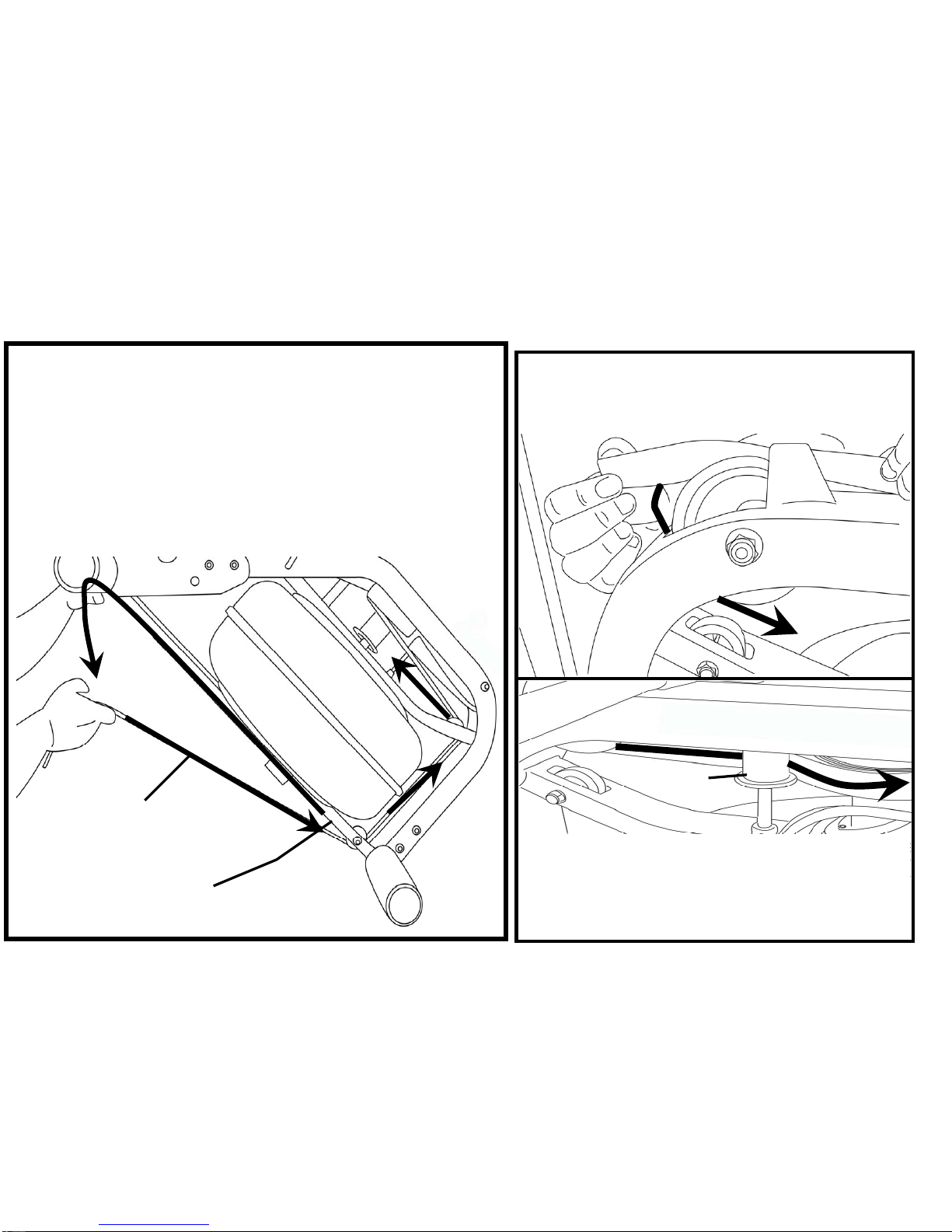
Removing the bungee shock cord:
Bungee shock cord
Bungee attachment point
Once bungee cord and upper frame
hole are aligned, push the bungee cord
up and through the frame as shown
First, move the rowing handle to it’s farthest forward point on the mainframe, then cut the plastic end tie and follow
the drawing above for bungee removal. Next, remove the upper frame plug to allow the bungee shock cord to be
threaded through the top of the frame. Note: You will need to rotate the belt/bungee pulley to align the holes prop-
erly. Should the belt drop off of during the bungee change, please refer to the previous pages for “Attaching/
Reattaching the rower belt”.
Upper frame plug Upper frame hole
Belt/ bungee pulley

Replacing the bungee shock cord:
Bungee shock
cord
Bungee attachment
point
Reinstall the shock cord through the upper frame, along the opposite side of
idle wheel, through the mid frame and lower bungee pulleys and then tie off
with plastic tie wrap to correct tension. Replace frame plug
Tip: Correct bungee tension is achieved when enough recoil is present for the
rowing handle to easily reach the front of the rower pulley belt bracket at the
far front of the frame. If the rowing handle will not reach rearward to the end
of the seat rail, the bungee cord is over-tightened and will require adjustment.
Pull Bungee
through until
seated securely

Troubleshooting:
Fault Probable Cause Solution
Water changes color or becomes
cloudy.
Rower is in direct
sunlight or has not had
water treatment.
Change rower location to reduce direct ex-
posure to sunlight. Add water treatment and
blue dye or change tank water as directed
in the water treatment section of this man-
ual.
Rower belt slipping off belt/ bungee
pulley. Bungee not under
enough tension.
Tighten bungee cord following the instruc-
tions given in the change bungee section of
this manual.
Front leg rises slightly during
vigorous rowing
M10X180mm vertical
seat rail bolt is slightly
too loose.
Tighten bolt 1/2 turn and try again. Tighten
as needed until problem stops. Note: Over
tightening this bolt can damage the seat
rail. Only tighten bolt until mid leg begins to
lift slightly from the ground. Refer to “Fine
tuning the Neptune Challenge” for details.
The Neptune Challenge computer
does not illuminate after battery in-
stallation.
Batteries installed in-
correctly or need re-
placing.
Reinstall batteries in correct position and try
again. If the LCD screen fails to illuminate,
replace batteries. If this fails, contact your
local service center.
Neptune Challenge Computer screen
illuminates, but does not register
when rowing.
Loose or failed con-
nection.
Check that the computer lead is connected
properly. If it is connected then contact
your local service center.

Parts List
KEY QTY PART NO.DESCRIPTION KEY QTY PART NO.DESCRIPTION
1 1 90701 Seat - LS-E22 30 2 90905 Footplate Bolt M8x15
2 1 65121 Seat Frame Left 31 2 90906 Spring Washer M8x10mm
3 1 65121 Seat Frame right 32 2 90907 Foot Strap Velcro
4 4 90705 Inner Axle Bushing (Short) 33 1 90402 Rear Leg Internal Mounting Bracket
5 3 60707 Bolt M8x120 34 1 20029 Nylock nut M10
6 6 60708 Washer M8 35 1 90401 Rear Leg
7 5 60709 Nut Nylock M8 36 1 90802 Rear Leg End Cap 60mm
8 4 60710 Washer M6x11 37 1 60804 Seat Rail End Cap 75x75
9 4 60711 Screw M6x20 38 1 71025 Main shaft Rear Bracket Bolt M10x25mm
10 4 65702 Seat Wheel 39 1 61007 Tank Level Decal
11 2 90706 Inner axle Bushing (Long) 40 2 91003 Main Frame Logo Decal
12 1 90707 Lower Seat Wheel Axle Spacer 41 1 61004 Main Frame Upper Warning Decal
13 1 90708 Round Magnet 42 1 61006 Main Frame Lower Warning Decal
14 1 90801 Rail 43 1 60615 Bungee Cord 8mmx1250 with Clip 60617 & Tie 61008
15 2 60803 Rubber Bump Stop - Seat 44 1 90101 Welding Component
16 4 60807 Rubber Bump Stop Screw M6x10 45 1 60102 Upper Mid Frame
17 2 90812 Rail Decal 46 1 60104 Roller Belt Pulley Bracket
18 1 90803 Sensor With Lead 47 1 60107 Welding Component
19 2 90804 Sensor Mounting Screw M3x8 48 1 90106 Computer mount
20 1 60806 Footplate Bolt M10x180 49 1 90105 Computer Stalk piece
21 1 60809 Plastic Dome Cap For Vertical Seat Rail Bolt 10mm 50 2 90102 Rower Handle Bar Catch
22 7 60810 Nut Nylock (M10) 51 3 60301 Welding Component
23 5 60135 Bolt (M10x95) 52 3 60302 Welding Component
24 2 60134 Washer (M10) 53 1 60303 Welding Component
25 10 60149 Spring Washer M10 54 1 60304 Flywheel Upper Shaft
26 2 90901 Plastic Footplate 55 1 60901 Welding Component
27 1 90902 Footplate Axle 12mmx388 56 1 60902 Belt Bungee Pulley Inc. 90136 Bearing
28 2 90903 Footplate Spacer Nylon D25xD17x19L 57 2 90136 One Way Bearing INA-HFL2016
29 1 90904 Internal Footplate Spacer 17mmx1.5Tx110L 58
Parts list:

KEY QTY PART NO. DESCRIPTION KEY QTY PART NO. DESCRIPTION
59 1 60903 Velcro Strip 87 5 61001 Tank Bonding Strip 3M-VHB
60 4 60108 Bungee Pulley Spacer 88 2 60147 Washer O Ring
61 2 60109 Bungee Pulley 89 1 60148 Computer Lead
62 2 60110 Belt Pulley Spacer 90 1 60150 Nylon Main Shaft Bushing - Upper
63 1 60111 Belt Pulley 100mm (inc. 2x60112 Bearing) 91 2 60606 Heel Adjuster Plastic Spacer
64 4 60112 Ball Bearing 6000ZZ 92 1 90103 Computer
65 1 60113 Main Shaft Oil Bushing - Lower 93 2 90104 Hook
66 1 60114 Magnet Ring (inc. 6x60124 Magnet) 94 1 90107 Computer Plastic Spacer
67 1 60115 Flywheel Shaft Spacer 95 1 60201 Welding Component
68 1 60116 Tank Lower 96 1 60202 Welding Component
69 1 60117 Tank Upper 97 1 60203 Welding Component
70 1 60118 Tank Large Ring Seal 98 2 60204 Welding Component
71 1 60119 Idle wheel inc. 2x60112 Bearing 99 1 60103 Welding Component
72 1 60120 Roll Pin 6mm 100 2 60205 Welding Component
73 1 60121 Bolt (M10x90) 101 2 90206 Lower Main Frame Mounting Bracket - Rear
74 1 60123 Idle Shaft Upper Frame Mount 10mm 102 4 60209 End Cap 76.2mm Round
75 1 60125 Idler Pulley Shaft 103 4 60210 Transport Wheel Fasterner
76 2 60126 C Clip 10mm 104 2 60211 Transport Wheel 76.2
77 1 60127 Grub Screw M4x6 105 2 60212 End Cap 25x50mm
78 2 60128 Bolt (M8x65) 106 1 90502 Rower Handle
79 2 60130 Frame Rubber Bumper 107 1 90503 Rower Handle Belt Bracket
80 24 60132 Screw (M3x20) 108 2 90506 Handle Grip
81 24 60133 Nut Nylock (M3) 109 1 60507 Rower Handle Complete
82 1 60137 Tank/Main Frame Spacer 110 1 60505 Inner Rowing Handle Foam
83 1 60138 Impeller End Cap 111 1 60508 Velcro Strip for Belt (Note: Combined with 60903)
84 2 60139 Tank Internal Screw S/Steel M6x15
85 3 90144 End Cap - round PVC 25.4mm
86 1 60145 Frame Plug 38.1mm
Parts list:
Table of contents
Other First Degree Home Gym manuals


Popular Home Gym manuals by other brands

Sportplus
Sportplus SP-HG-010 user manual

ICON Health & Fitness
ICON Health & Fitness . JMTBW10.0 user manual

Impex
Impex MWM 982 owner's manual

Impex
Impex Marcy Pro NS-6023RW Assembly & owners manual

Weider
Weider 184 Bench Manuel de l'utilisateur

BLUEFIN Fitness
BLUEFIN Fitness LIFT Multi Functional Folding Weights Bench instruction manual


