First Power Stinger Owner's manual

PATENT
PENDING
Owner / Operator’s Manual Rev B.2
Version 1
8941 Dutton Dr,
Twinsburg, Ohio
44087
330-963-2050

Table of Contents
Stinger® Kit Overview
………………………………………………………………………………
1
Operation Guide
…………………………………………………………………………………….
2
GoPro® Camera Installation and Usage
……………………………
……………..
7
Battery Replacement
……………………………………………………………………………..
9
Replace Transmitter Battery ……………………………………………………
9
Replace Receiver Batteries ……………………………………………………….
10
Stinger® Fluid Overview
…………………………………………………………………………
1
3
Recommended Maintenance and Safety
…………………………………
…
……
1
4
Specifications and Certifications
………………………………………
…………………
1
5
Warranty Information
…………………………………………………………………………….
16
Parts Diagram
…………………………………………………………………………………………..
17
Stinger® Kit Overview
1
|
©
2 0 1 9 F i r s t P o w e r G r o u p L L C
Stgr
-
Manual
-
V1 Rev. B.2
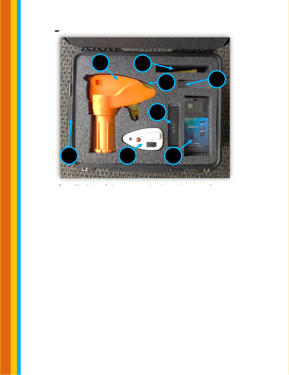
1. Case: The Stinger® Kit comes in a durable and waterproof case.
2. Main Assembly: Non-conductive housing that safely protects the can
from an electric arc and houses the plumbing and valve to route the
Stinger® fluid to the nozzle.
3. Receiver: Allows for remote communication between the main
assembly, Key Fob and the transmitter to turn the dispense on and off.
4. Transmitter: Allows for Stinger® fluid to be sprayed through a press of a
button from a safe location.in the Transmitter and Receiver.
5. Nozzles: The kit comes with a spray nozzle and 2 spare spray nozzles.
These nozzles are used to disperse the Stinger Fluids in a direct stream.
6. GoPro® Camera: Captures live video of where the Stinger fluid is being
sprayed.
7. Smartphone: Used to display video from the GoPro® Camera.
8.
Batteries: Six 9V batteries are provided in addition to the batteries
installed in the Receiver and Transmitter.
5
2
3
4
8
6
7
1
Operation Guide
2
|
©
2 0 1 9 F i r s t P o w e r G r o u p L L C
Stgr
-
Manual
-
V1 Rev. B.2
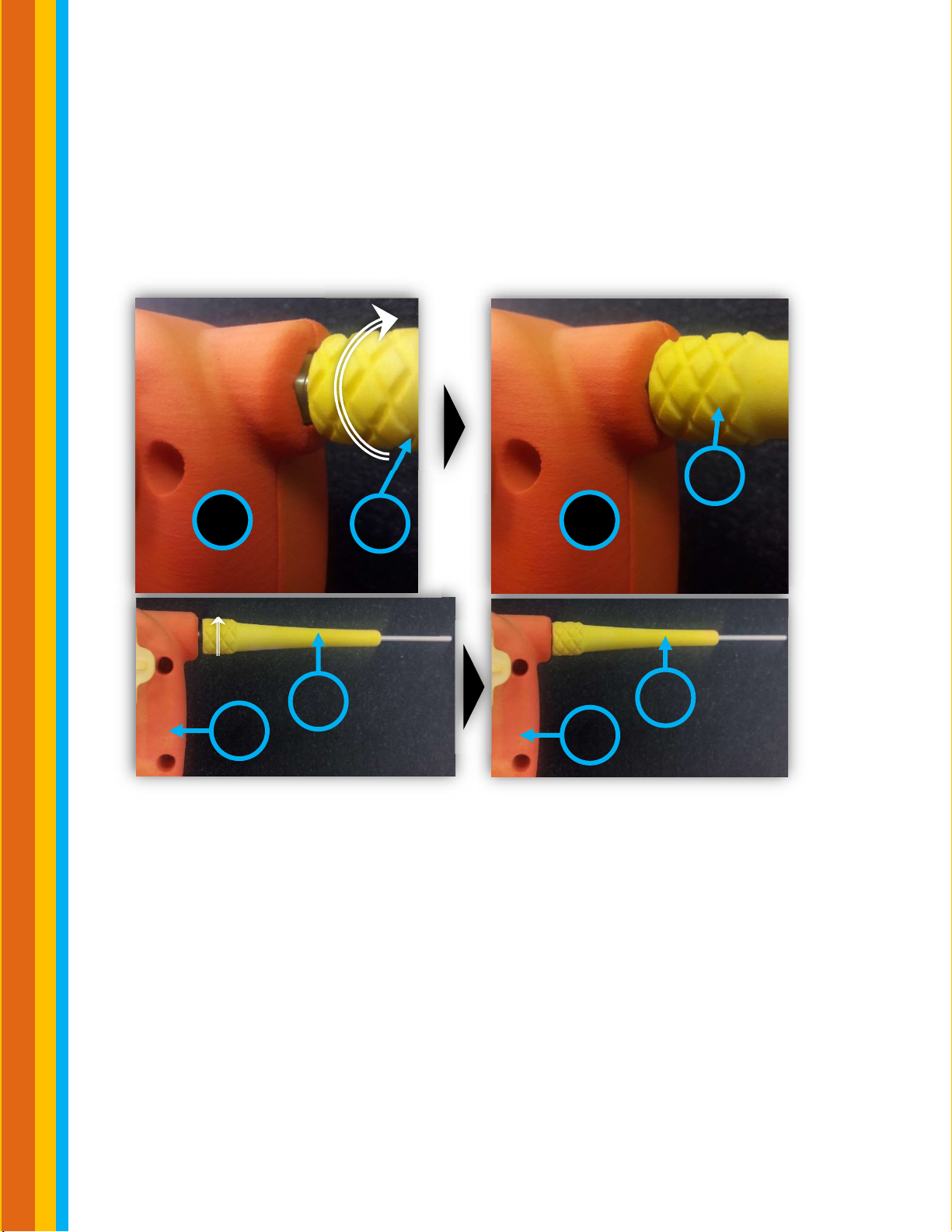
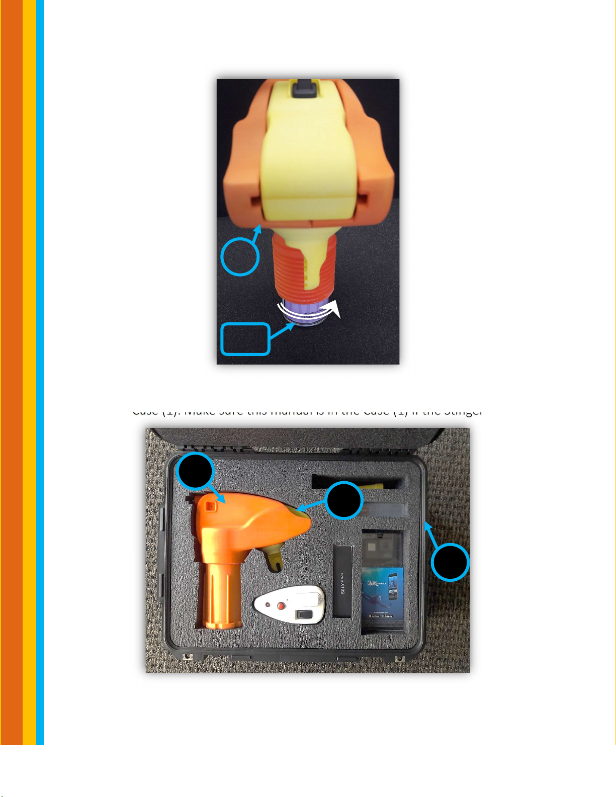
Step 1: Take the Main Assembly (2) out the Case (1). Typically, the Receiver (3)
is left in the Main Assembly (2). If the Receiver (3) is not installed, installed it
using the procedure shown on page 16. Begin with screwing a Nozzle (5) into
the threaded insert on the Main Assembly (2). Twist with your hand until the
Nozzle (5) stops turning which is shown in the after images.
2
5
2
5
2
5
2
5
Before
After

Operation Guide
3
|
©2019 FirstPower Group LLC
Stgr
-
Manual
-
V1 Rev. B.2
Step 2: Unscrew the Can Cap on the
bottom of the Main Assembly (2) in the
direction indicated.
Step 3: Fully screw in the threaded top
of the appropriate Stinger® Fluid Can
(1FR™, 2C™,3PAO™) with your hand
until hand tight. It is normal to hear a
pressure release sound before the can
is fully screwed in. Typically, you should
give the can another ½ turn after
hearing the pressure release.
Warnings: If it is hard to screw in the
can, remove the can and try again. DO
NOT FORCIBLY SCREW IN THE CAN. If
the can isn’t fully screwed in, the Can
could leak or
fail inside the Can Housing. The Stinger® can only be used with proprietary
Stinger® fluids, DO NOT attempt to insert other cans into the Stinger®.
Step 4: After installing a can, be sure
to fully screw the orange Can Cap to
the Main Assembly (2) until hand tight.
2
Can
Cap
2
Can
Housing
Can
2
Can
Cap

Operation Guide
4
|
©2019 FirstPower Group LLC
Stgr
-
Manual
-
V1 Rev. B.2
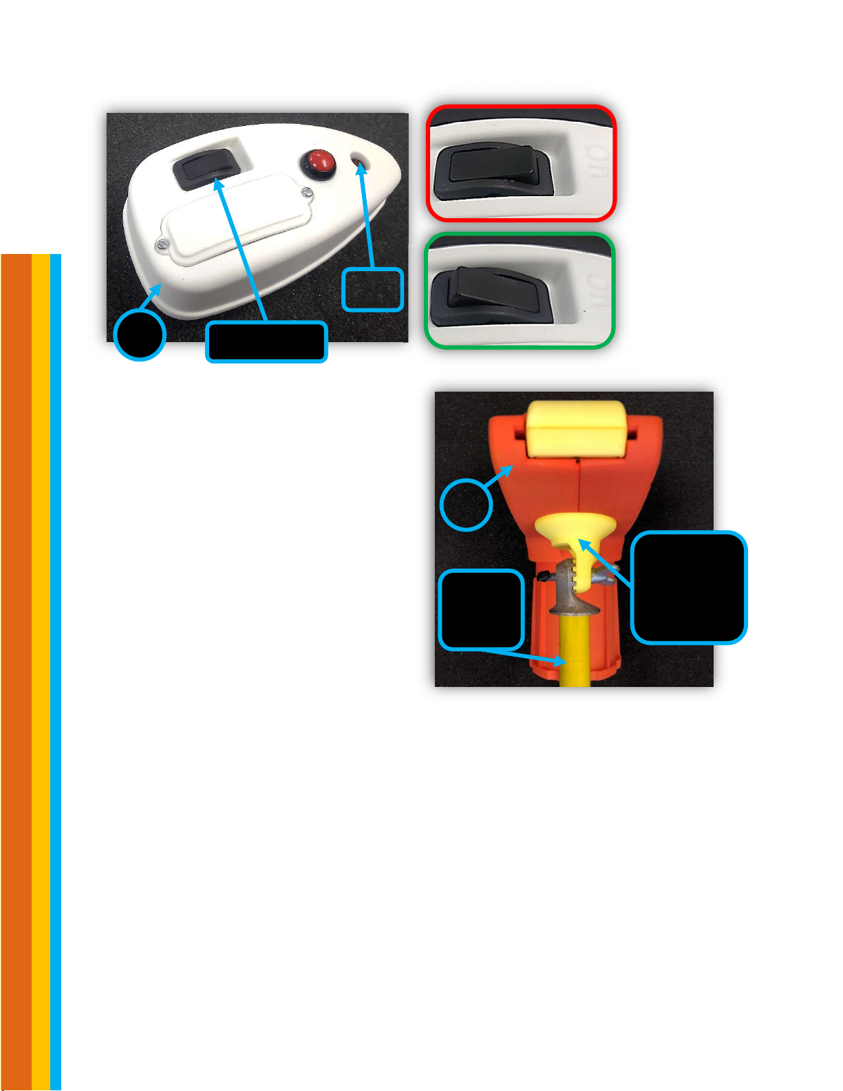
Step 5: Power on the Receiver (3) in the Main Assembly (2) by flipping the Switch
from the Off Position to On Position.
Step 6: Test fluid stream into a
rag away from equipment for
proper function.
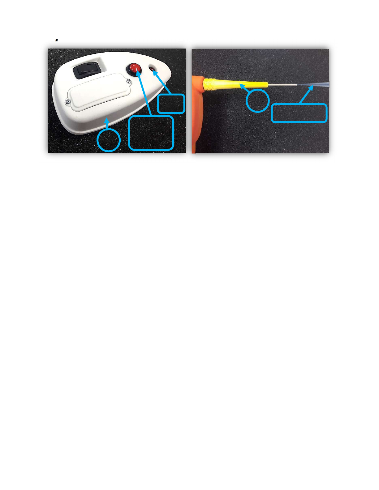
Step 7: Next, power on the Transmitter (4) by flipping the switch from the OFF
position to the ON position. After switching the Transmitter ON, the LED will go
ON for about 1 second, off for about 1 second, and then ON again for about 1
second to indicate it has powered up OK. Wait until the LED has gone through
the flashing process to press the red button. If the LED doesn’t go ON when the
switch is flipped to the ON position, the transmitter may not be functioning.
Warning: Any transmitter will control all powered receivers within range. Make
sure that all other Stingers that are not in use have their receivers and
transmitters turned off.
2
3
Switch
Switch in
the OFF
Position
Switch in
the ON
Position
Operation Guide
5
|
©2019 FirstPower Group LLC
Stgr
-
Manual
-
V1 Rev. B.2
Step 8: Attach the fully assembled
Stinger® to the hot stick using the
yellow universal toothed hot stick
adapter (Hot Stick Adapter). Be sure to
attach the Main Assembly (2) at an
appropriate angle to easily aim stream
of Stinger fluid to the desired location.
We recommend you practice moving
and operating the stinger when the hot
stick is fully extended before using it in
the field.
Step 9: Press the Button on the Transmitter (4) to dispense the liquid. The liquid
will continuously stream out of the Nozzle (5) while the Red button is pressed. If
the LED does not go ON when the button is pressed, the Receiver may be not
functioning.
Hot
Stick
Adapter
Hot
Stick
2
4
Switch
LED
Switch in
the ON
Position
Switch in
the OFF
Position
Operation Guide
6
|
©2019 FirstPower Group LLC
Stgr
-
Manual
-
V1 Rev. B.2
Step 10: Turn the switches on the Receiver (3) and Transmitter (4) to the OFF
position after use (see Steps 5 and 6 to see what each switch position looks like).
Remove the Nozzle (5) from the Main Assembly (2). Place the Transmitter (4),
and Nozzle (5) back in the Case (1).
Step 11: Remove the can cap then, unscrew the can. Make sure the Main
Assembly (2) is upright to prevent the Stinger® fluids from leaking onto your
clothes when the can is unscrewed. Then reinstall the can cap.
5
Spray
4
Red
Button
LED
Operation Guide
7
|
©2019 FirstPower Group LLC
Stgr
-
Manual
-
V1 Rev. B.2
Step 12: Place the Main Assembly (2) with the Receiver (3) into the Case (1) and
close the Case (1). Make sure this manual is in the Case (1) if the Stinger is not in
use.
2
Can
1
3
2
GoPro® Camera Installation and Usage
8
|
©
2 0 1 9 F i r s t P o w e r G r o u p L L C
Stgr
-
Manual
-
V1 Rev. B.2
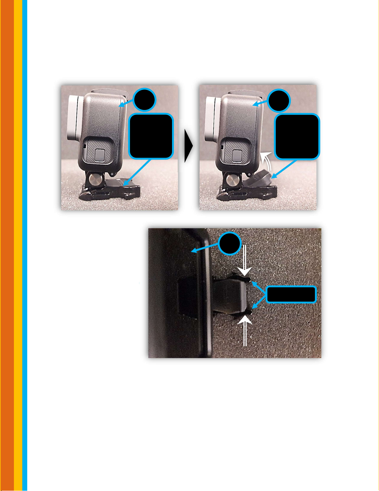
Step 1: Lift the grey Rubber Locking Plug that is a part of the GoPro® Camera (6)
so that it is touching the back of the camera.
Step 2: To easily slide the
GoPro® Camera (6) into
the Camera Mount on the
Main Assembly (2) shown
on the next page, gently
pinch the black plastic Clip
Ends.
6
Clip Ends
6
Rubber
Locking
Plug
6
Rubber
Locking
Plug
Before
After
This product and/or service is not affiliated with, endorsed by or in any way associated with
GoPro Inc.
or its products and services. GoPro, HERO, Session, Karma and their respective logos are trademarks
or registered trademarks of GoPro, Inc.
GoPro® Camera Installation and Usage
9
|
©2019 FirstPower Group LLC
Stgr
-
Manual
-
V1 Rev. B.2
This product and/or service is not affiliated with, endorsed by or in any way associated with GoPro Inc. or its
products and services. GoPro, HERO, Session, Karma and their respective logos are trademarks or registered
trademarks of GoPro, Inc. . (See- https://gopro.com/en/us/shop/cameras/hero7-silver/CHDHC-601-
master.html) for pairing.
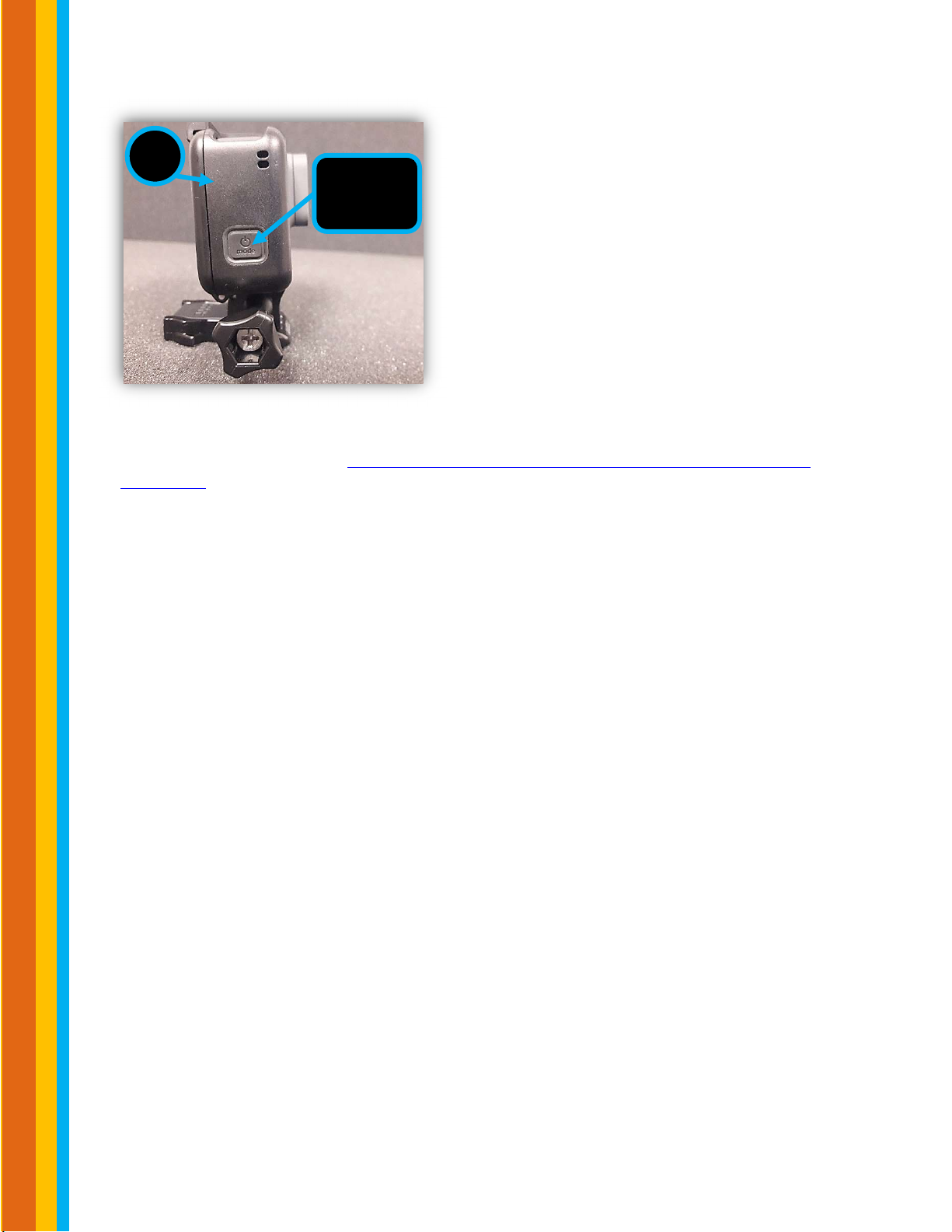
Step 5: After use, gently remove the camera from the Main Assembly (3) and turn it
off. Steps 1-4 for reference. Place the Smartphone (6) and the camera back into the
Case (1)
6
Power
Button

Battery Replacement
10
|
©
2 0 1 9 F i r s t P o w e r G r o u p L L C
Stgr
-
Manual
-
V1 Rev. B.2
Replace Transmitter Battery
The status of the batteries is indicated by the transmitter LED when the button is
not pressed. If the LED flashes red 1 time every 3 seconds, then transmitter has
low battery voltage. If the LED flashes red 2 times every 3 seconds, then the
receiver has low battery voltage. If the LED flashes red 3 times every 3 seconds,
both have low battery.
Step 1: Make sure that the
Transmitter is turned off. Then use a
#4 flat head screwdriver to unscrew
each screw on the battery door. Be
sure to not completely unscrew the
screws from the battery door or else
the washers will detach.
Step 2: Use standard Alkaline 9V
batteries for replacement. Remove old
battery and carefully replace with 1
new 9V battery. Put the battery door
securely back on and verify the
transmitter works by flipping the on
switch, the red light should blink
twice.
LED
Button
Flat Head
Screws
Battery
Door
Battery
Door
Alkaline
9V
Battery
LED
Battery Replacement
11
|
©2019 FirstPower Group LLC
Stgr
-
Manual
-
V1 Rev. B.2
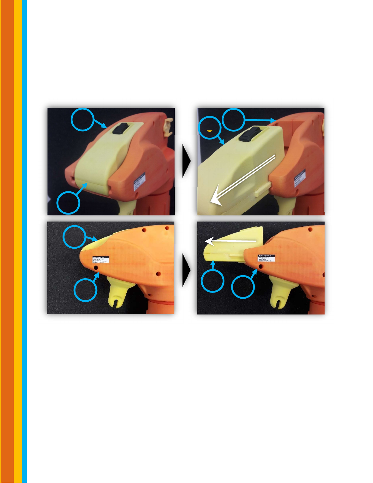
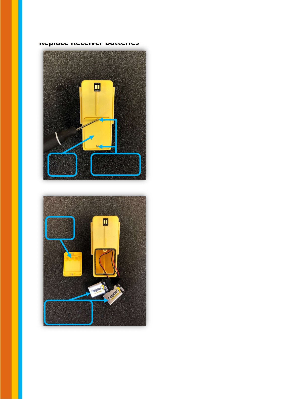
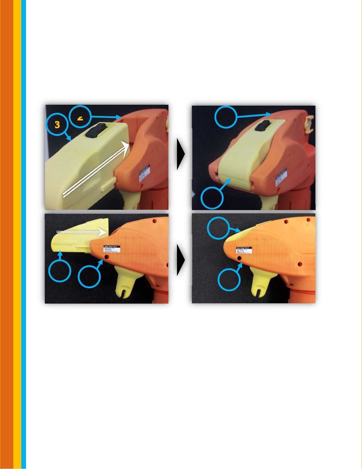
Replace Receiver Batteries
Step 1: Remove the Receiver (3) from its initial position shown in the “Before”
figures. Gently slide it out the back of the Main Assembly (2) which is presented
in the “After” figures.
2
3
3
2
3
2
3
2
Before After
Battery Replacement
12
|
©2019 FirstPower Group LLC
Stgr
-
Manual
-
V1 Rev. B.2
Replace Receiver Batteries
Step 2: Make sure that the Receiver is
turned off. Then use a #2 Philips
screwdriver to unscrew each screw on
the battery door. Be sure to not
completely unscrew the 2 screws from
the battery door or else the washers
will detach.
Step 3: Use standard Alkaline 9V
batteries for replacement. Remove the
old batteries and carefully replace with
2 new 9V batteries
Philips Head
Screws
Battery
Door
Battery
Door
Alkaline 9V
Batteries

Battery Replacement
13
|
©2019 FirstPower Group LLC
Stgr
-
Manual
-
V1 Rev. B.2
Replace Receiver Batteries
Step 4: Make sure the battery wires are
routed as shown on this photo. This will
prevent wire damage and allow proper
battery door installation. Battery door
must be installed flush. Screws must be
recessed after installing. DO NOT
FORCE screws in, if they don’t easily
screw in so they are recessed, unscrew
and re-install.
Battery
Door
Alkaline 9V
Batteries
Battery Replacement
14
|
©2019 FirstPower Group LLC
Stgr
-
Manual
-
V1 Rev. B.2
Step 4: Finally, insert the Receiver (3) back into the back of the Main Assembly
(2) as shown in the “Before” figures. Confirm the that Receiver (3) is fully
inserted into the Main Assembly (2) as shown in the “After” figures.
2
3
3
2
3
2
3
2
Before After

Stinger® Fluid Overview
15
|
©
2 0 1 9 F i r s t P o w e r G r o u p L L C
Stgr
-
Manual
-
V1 Rev. B.2
1FR - Penetrant
Stinger® Fluid 1FR is a fast-acting penetrant
that frees corroded disconnect switches,
bushings, and bolts. 1FR has a proprietary
threaded top which only allows it to be
used in the Stinger®. Simply apply to a
seized joint and let sit for 20-30 minutes to
ensure penetration and repeat if needed.
This fluid can be used on energized
equipment.
2C - Cleaner
Stinger® Fluid 2C is a switch and contact
cleaner. 2C has a proprietary threaded top
that allows it to only be used in the
Stinger®. This fluid can be used on
energized equipment. DO NOT use on
polycarbonate plastics, this cleaner can
harm plastics.
3PAO - Lubricant
3PAO is a high-quality synthetic lubricant,
containing anti-wear additives. It is great
for lubricating seized parts, such as gears
and knuckles. After using 1FR to open the
switch, 3PAO may be used to make the
switch move freely and ensure it closes
properly. This fluid can be used on
energized equipment.

Recommended Maintenance and Safety
16
|
©
2 0 1 9 F i r s t P o w e r G r o u p L L C
Stgr
-
Manual
-
V1 Rev. B.2
Recommended Maintenance
Extend the life of the Stinger® by not storing outdoors or in extreme
conditions
Wipe the Stinger® using a clean lint-free cloth after each use.
o DO NOT USE CHEMICAL SOLVENTS AS THIS WILL VOID WARRANTY.
THIS WILL COMPROMISE THE DIELECTRIC PROPERTIES OF THE
STINGER®.
o DO NOT SUBMERGE THE STINGER® THIS WILL VOID WARRANTY
Power off Receiver and Transmitter when not in use.
Remove can from inside Stinger® when not in use.
Remove batteries when stored long term.
Safety
Stinger®
Do not operate with line clearance without the can cap installed
Make sure to practice operating the Transmitter while holding the hot
stick. Also, practice getting used to the weight of the Stinger®.
Always make sure that the Receiver is fully inserted into the Main
Assembly to avoid it falling out with rough usage.
Stinger® Fluids
If any fluids contact skin, please wash the area of contact immediately and
with soap and water.
Do not ingest any of the fluids, if ingested please contact emergency
services.
Do not store fluids near extreme heat or cold because cans are under
pressure.

Specifications and Certifications
17
|
©
2 0 1 9 F i r s t P o w e r G r o u p L L C
Stgr
-
Manual
-
V1 Rev. B.2
The Stinger®:
Dimensions: 10” X 4.25” X 14.6”
Weight: 4 lbs
Material: dielectric resin
o ASTM D149 tested to 221 kV/in
The Stinger® passes a Proximity High Voltage Withstand test to 230kV
Stinger® Fluids:
All Stinger® Fluids have passed ASTM 3065D for non-flammability when
applied using the Stinger®

Warranty Information
18
|
©
2 0 1 9 F i r s t P o w e r G r o u p L L C
Stgr
-
Manual
-
V1 Rev. B.2
The Stinger® is warranted for one year from the date of purchase with a factory
warranty. This warranty applies to parts and labor for any defects that are
corrected in our shop when the product has been returned for repair. Pass
through warranties provided where applicable.
Table of contents


