Westward 24AD42 Service manual

Please read and save these instructions. Read through this owner’s manual carefully before using product. Protect
yourself and others by observing all safety information, warnings, and cautions. Failure to comply with instructions could
result in personal injury and/or damage to product or property. Please retain instructions for future reference.
Operating Instructions and Parts Manual 24AD42
65 Ft. AUTO REWIND HOSE REEL
FORM ZYZ42
Printed in China
07/13
Description
The Wall-Mounted Hose Box with automatic spring hose recoil is designed for irrigation of the garden and is intended
for use in hobby gardens.
Parts list
NO Description Quantity
A Reel 1 pc
B Mounting bracket 1 pc
C Aluminum tube 1 pc
D Expansive bolt 4 sets
Unpacking
1. Remove product from its packaging.
2. Check the product and accessories. To ensure there was no damage in shipping.
Specification & Dimensions
24AD42
420PSI
0PSI -150PSI
65
28
10-1/8
17-7/8
20.39
General Safety Information
Read the Operating Instructions before Initial operation.
Setting up your hose reel:
1. Choose a mounting location that is near a faucet or source of water.
2. Mount the bracket (B) to the wall using the expansion bolts (D). Make sure that all four (4) bolts are in the
center of the holes. Note: All bolts must be used for safe mounting.
Max. Pressure Pressure Range Main Hose Dimensions (Inches) Weight
Model (Bar) (Bar) (Feet)Length Width Height (Pounds)
A
B
C

Westward Operating Instructions Manual 24AD42
2
65 Ft. AUTO REWIND HOSE REEL
3. Attach the hose reel (A) to the mounting bracket by centering the reel over the bracket and inserting the
aluminum tube (C) through both the hose reel and the mounting bracket by tapping with a rubber mallet (as
shown in Figure 1).
If correctly installed the hose reel should be able to rotate 180 degrees.
Using your hose reel:
PULLING OUT THE REQUIRED HOSE LENGTH:
While pulling out your hose, you will hear 3 clicking sounds repeatedly. Discontinue pulling out the hose after the first
or second click in order to lock the hose at the desired length.
Retracting the hose:
1. Turn off the water and release the pressure from the hose by opening the nozzle.
2. Pull the hose until there are no longer any clicking sounds coming from the reel, which means the lock is
released, and then hose will go back automatically.
3. WALK the hose back into the reel as it rewinds.
TO AVOID INJURY, DO NOT LET GO OF THE HOSE WHILE IT IS REWINDING. THE HOSE
MUST BE WALKED BACK ALL THE WAY TO THE REEL.
4. The inner spring will rewind your hose the most conveniently, if you have at least 20 ft. (6 m.) pulled out of
the reel.
Care and maintenance:
1. Always turn off the water at the faucet when the hose reel is not in use.
2. Do not immerse the hose reel in water.
3. The life of the hose reel may be extended if it is not installed in direct sunlight.
4. Completely drain all the water out of the hose and inlet hose prior to any periods of freezing weather or
winter storage.
5. If the inner spring begins to have difficulty rewinding the hose, it may be fatigued. Follow the procedures for
adding tension found in the TROUBLESHOOTING section of this manual.
6. This product is intended for COLD WATER usage only. Do not use with chemicals of any kind.
Figure1 /Illustration 1 / ilustración1

Westward Operating Instructions Manual 24AD42
3
65 Ft. AUTO REWIND HOSE REEL
Troubleshooting- Spring Tension:
1. Disconnect the hose reel from the mounting bracket by removing the
aluminum rod.
2. Remove the side cover on the opposite side of the water system.
3. Use pliers to tightly hold the center ring using the two openings
provided (Figure 2). DO NOT GRIP THE EXTENDED PLASTIC NUT
IN THE CENTER OF THE RING.
4. While holding with the pliers, remove the three (3) screws that hold the
center ring in place.
5. Using the pliers, pull the center ring away from the reel, turn it counter-
clockwise a few times to tighten the spring and then push the ring back
into place.
6. Carefully make sure that the screw holes line up with the holes in the reel
and then reinstall the three (3) screws. Do not over tighten.
7. Replace the side cover on the reel.
Warranty: Should this product fail to perform satisfactorily due to defect or poor workmanship within ONE YEAR from
the date of purchase, return it to the place of purchase and it will be replaced free of charge. Incidental or
consequential damages are excluded from this warranty. The bulb is not covered under warranty.
Figure2 /Illustration 2 / ilustración2

Westward Operating Instructions Manual 24AD42
Manufactured for Grainger International, Inc.
100 Grainger Pkwy., Lake Forest IL 60045 U.S.A 4
65 Ft. AUTO REWIND HOSE REEL
For Repair Parts, Call 1-800-323-0620
24 hours a day-365 days a year
1
Outer casing
2
17
Handle
1
2
Coil wheel
2
18
Handle base
2
3
Spring
1
19
Window
1
4
Mounting bracket
1
20
Hose stop
1
5
Center shaft
1
21
Main hose
1
6
Ratchet
1
22
Closed window
1
7
Right-and-left cover
2
23
Spring fix cover
1
8
Pallet
1
24
Toothed drive plate
1
9
Hose fixing nut
1
25
Toothed drive plate cover
1
10
Self-layering mechanism
1
26
Guide body
1
11
Pallet block post
1
27
Screw consolidated
1
12
Hose turntable
1
28
Inlet connector
1
13
Hose inlet
1
29
Metal post
1
14
Cover
2
30
Pulling spring
1
15
Supply to hose
1
31
In-phase rack
1
16
Aluminum tube
1
32
Rotating gear
1
Ref. No. Description Qty. Ref. No. Description Qty.

Por favor lea y guarde estas instrucciones. Lea este manual de instrucciones cuidadosamente antes de usar el producto.
Protéjase a símismo y a los demás observando toda la información de seguridad, advertencias y precauciones. El
incumplimiento de las instrucciones podría resultar en lesiones personales y / o daños al producto oa la propiedad.
Conserve las instrucciones para referencia futura.
Instrucción de Funcionamiento y Piezas Manuales 24AD42
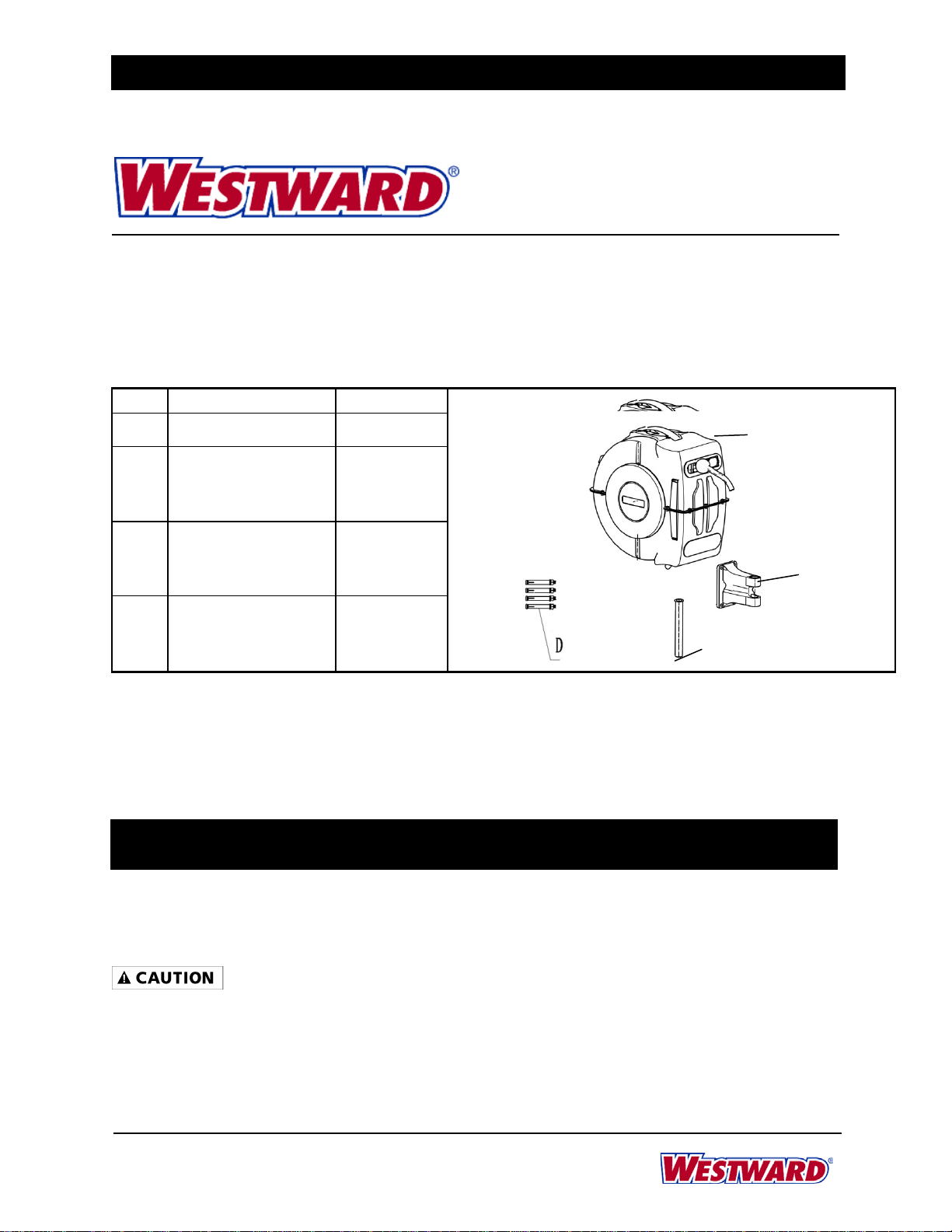
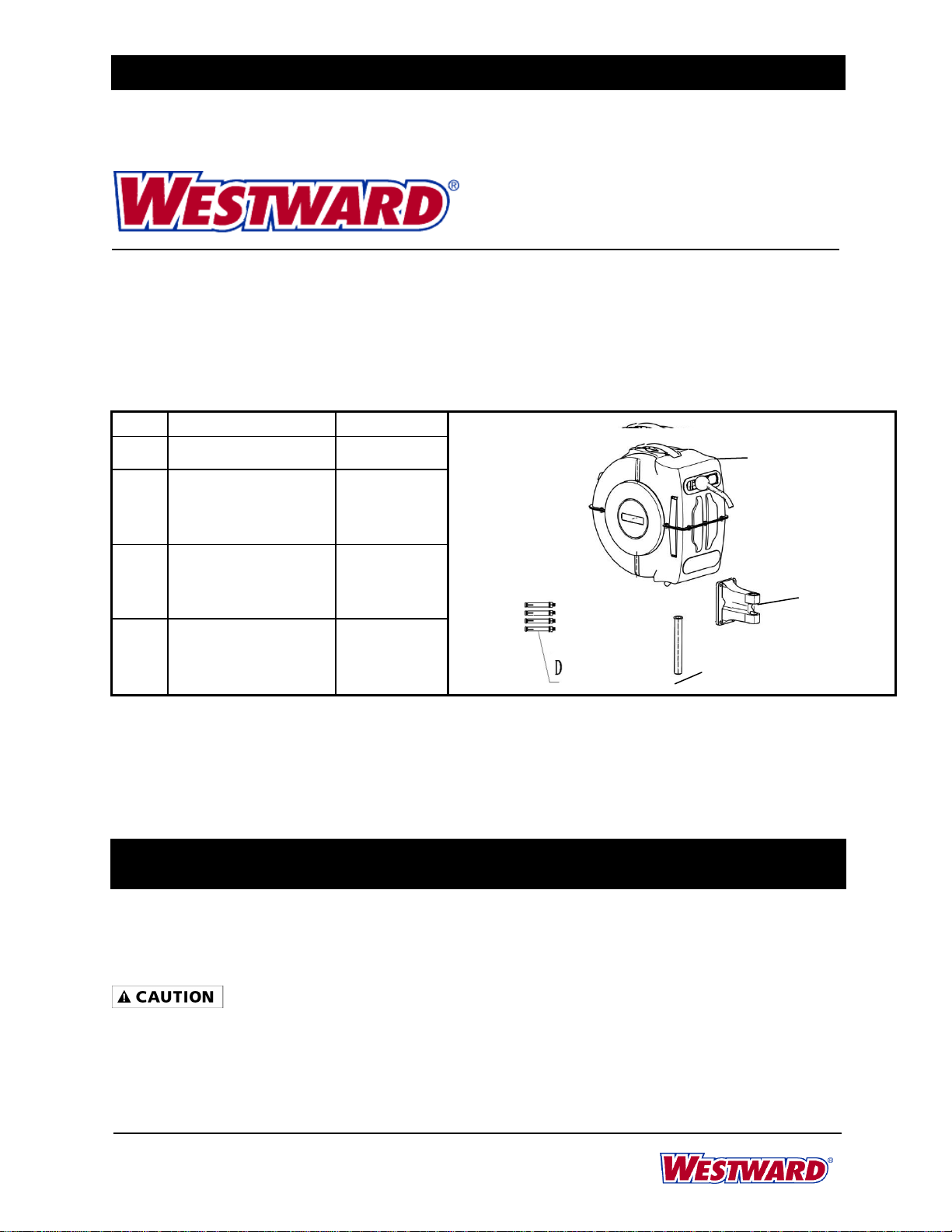
65 Ft. Carrete de Manguerra AUTO
Rebobinado
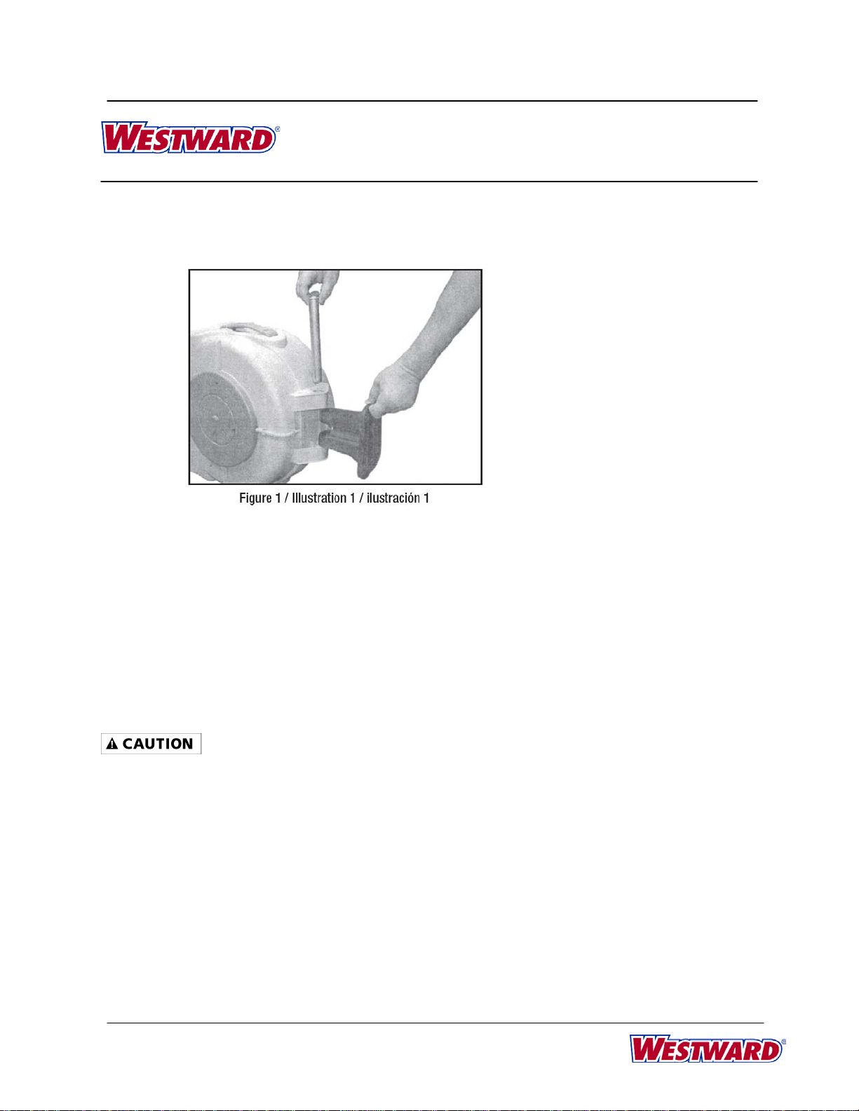
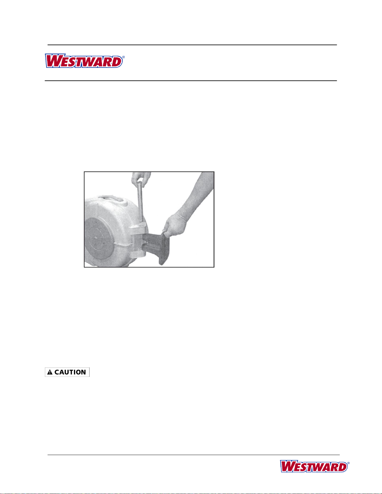
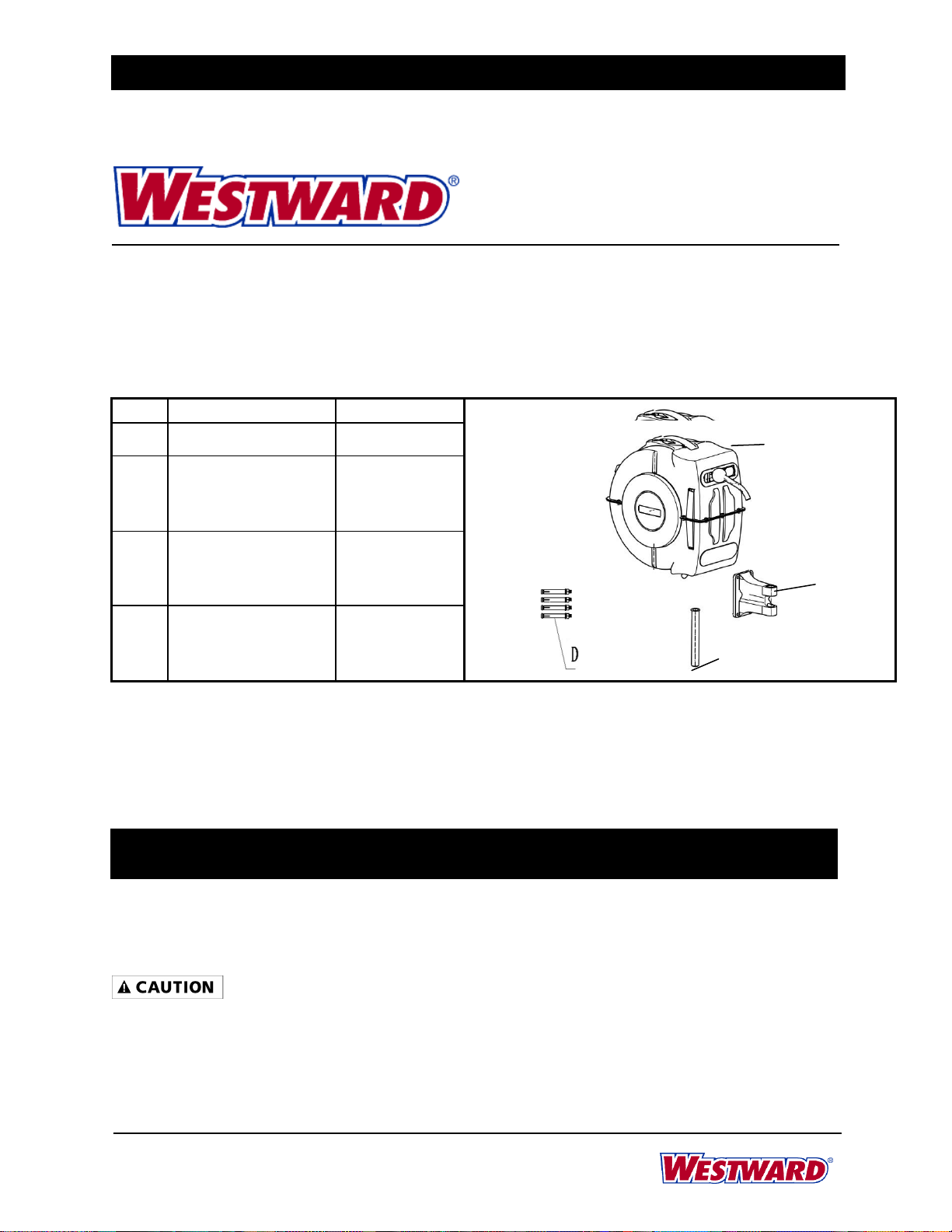
FORM ZYZ42
Printed in China
07/13
Descripción
La caja de la manguera montada en la pared con el retroceso automático de la manguera de resorte se ha diseñado
para el riego del jardín y para el uso por afición a jardines.
Lista de Piezas
NO
Descripción
Cantidad
A
Carrete
1 pc
B
Soporte de montaje
1 pc
C
Tubo de aluminio
1 pc
D
Perno expansivo
4 sets
Desembalaje
1.Retire el producto de su embalaje.
2.Compruebe el producto y sus accesorios para asegurarse de que no había daños en el transporte marítimo.
Especificaciones & Dimensiones
24AD42
420PSI
0PSI -150PSI
65
28
10-1/8
17-7/8
20.39
Información General de Seguridad
Lea el manual de instrucciones antes de la operación inicial.
Configuración del carrete de la manguera:
1. Elegir un lugar de montaje que estácerca de un grifo o fuente de agua.
2. Monte el soporte (B) a la pared con los pernos de expansión (D). Asegúrese de que las cuatro (4)
pernos están en el centro de los agujeros. Nota: Todos los tornillos deben usarse para el montaje seguro.
3. Una el carrete de la manguera (A) para el soporte de montaje al centrar el carrete sobre el soporte e
Max. Presión Gama de Presión Manguera Principal Dimensiones (Pulgadas) Peso
Modelo (Barra) (Barra) (Pie) Longitud Anchura Altura (Libras)
A
B
C
Table of contents
Languages:
Other Westward Tools manuals