6
0039-Radlagere120306.doc hu-rq
Chapter
3
© 2011 KLANN-Spezial-Werkzeugbau-GmbH, Germany
Instruction Manual
2. Product Description:
KL-0039-..Series Wheel Bearing Tool
2.1 Mechanical Drive
KL-0040-3008 Pull Spindle M20
Overall length: .......................................................................... 290 mm
Drive:................................................................................. (waf) 19 mm
Max. load:........................................................................................ 20 t
KL-0039-2030 Pull Spindle M20
Overall length: .......................................................................... 420 mm
Drive:................................................................................. (waf) 19 mm
Max. load:........................................................................................ 20 t
KL-0040-3009 Clamping Nut M20
Overall length: ............................................................................ 50 mm
Drive:................................................................................. (waf) 30 mm
KL-0039-1011 Retainer Adaptor
for Mechanical Spindle
This tool is necessary to retain the various KL-0039-.. or KL-0043-..
press/support sleeves if these are to be inserted by using the
mechanical drive.
The built-in ball bearing allows for accurate and professional working,
even under intensive load.
KL-0039-1002 Retainer Adaptor
for Clamping Nut and Pressure Spindle
This adaptor is designed to retain the various pressure-/support
sleeves of the KL-0039-.. or KL-0043-..Series.
Locating-Ø for clamping nut or pressure spindle: ....................... 20 mm
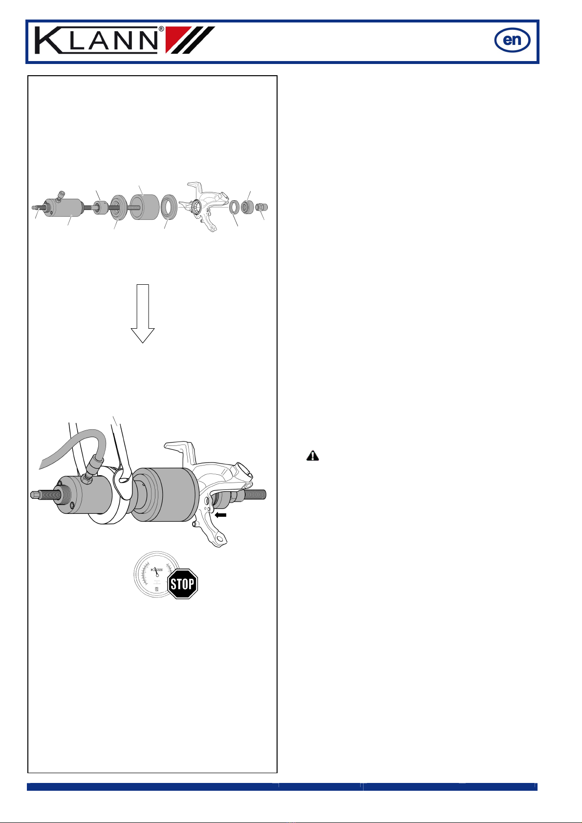
2.2 Hydraulic Drive
KL-0040-2500 Hydraulic Cylinder
Due to its special design as a tubular piston cylinder and the possibility
to be used in conjunction with various spindles, the hydraulic cylinder
KL-0040-2500 is suitable for pulling and pushing operations.
Note: Hydraulic pump KL-0215-35 M25 (accessory) is required to
drive the hydraulic cylinder.
KL-0039-1920 Pull Spindle M20 with Clamping Nut
Overall length: .......................................................................... 590 mm
Working travel: ......................................................................... 390 mm
Max. load:........................................................................................ 20 t
KL-0039-1003 Retainer Adaptor
for Hydraulic cylinder
This tool is necessary to retain the various KL-0039-.. or KL-0043-..
pressure-/support sleeves if these are to be inserted by using the
hydraulic cylinder KL-0040-2500.
(Connecting thread: M42 x 2)
KL-0039-1002 Retainer Adaptor
for Clamping Nut and Pressure Spindle
This adaptor is designed to retain the various pressure-/support
sleeves of the KL-0039-.. or KL-0043-..Series.
Locating-Ø for clamping nut or pressure spindle: ....................... 20 mm
Fig. 1: KL-0040-3008 Pull Spindle M20
Fig. 2: KL-0039-2030 Pull Spindle M20
Fig. 3: KL-0040-3009 Clamping Nut M20
Fig. 4: KL-0039-1011 Retainer Adaptor
for mechanical spindle
Fig. 5: KL-0039-1002 Retainer Adaptor
for clamping nut and pressure spindle
Fig. 6: KL-0040-2500 Hydraulic Cylinder
Fig. 7: KL-0039-1920 Pull Spindle with clamping nut M20
Fig. 8: KL-0039-1003 Retainer Adaptor
for hydraulic cylinder
Fig. 9: KL-0039-1002 Retainer Adaptor
for clamping nut and pressure spindle
Connection 3/8"
Thread M42 × 2
Thread
2¼"-14UNS
Pulling side
Pushing side