First Products SEEDA-vator SE60 Installation and operation manual

OPERATOR’S
MANUAL & PARTS LIST
(SEE SEPARATE MANUAL FOR SEEDER CALIBRATION)
SEEDA-vator
MODEL SE60
FIRST PRODUCTS INC.
P.O. Box 1425
Tifton, Georgia 31794 U.S.A.
Phone (229) 382-4768
1-800-363-8780
Fax (229) 382-0506
Web: www.1stproducts.com Email: Sale[email protected]
Ser. 300 thru 434
Printed in U.S.A.
PBREV0104

1
INTRODUCTION
Thank you for purchasing a SEEDA-vator. This piece of equipment has been carefully
engineered and manufactured to provide years of reliable service.
The SEEDA-vator is one of the most unique and versatile pieces of equipment on the
market today. It is designed for seeding in existing turf and bare soil.
We recommend that you carefully read the owners and operators manual prior to opera-
tion. Also ensure that all future operators read this manual and become fully trained be-
fore allowing them to use or maintain this equipment. Time spent becoming acquainted
with the safe operation, performance, and maintenance of the SEEDA-vator will add
longer life and greater satisfaction to your new purchase.
This machine is designed with safety in mind. However, if the machine is handled care-
lessly and not as instructed it can be a dangerous piece of equipment. Observe all safety
information in this manual and decals on the equipment.
The illustrations and data used in the manual were current at the time of printing. The
manufacturer reserves the right to make changes or add improvements to its products at
any time without incurring any obligation to make such changes to products manufac-
tured previously.
REMEMBER SAFETY IS ALWAYS FIRST !
ATTENTION:
x Read and understand the instructions and warnings carefully before using this
machine.
x Read the warranty located on page 18. Fill in the required information on the
warranty registration provided and return to the address on the front of this
manual. The warranty registration must be returned to validate warranty.

2
TABLE OF CONTENTS
SAFETY SYMBOLS .......................................................................................................................3
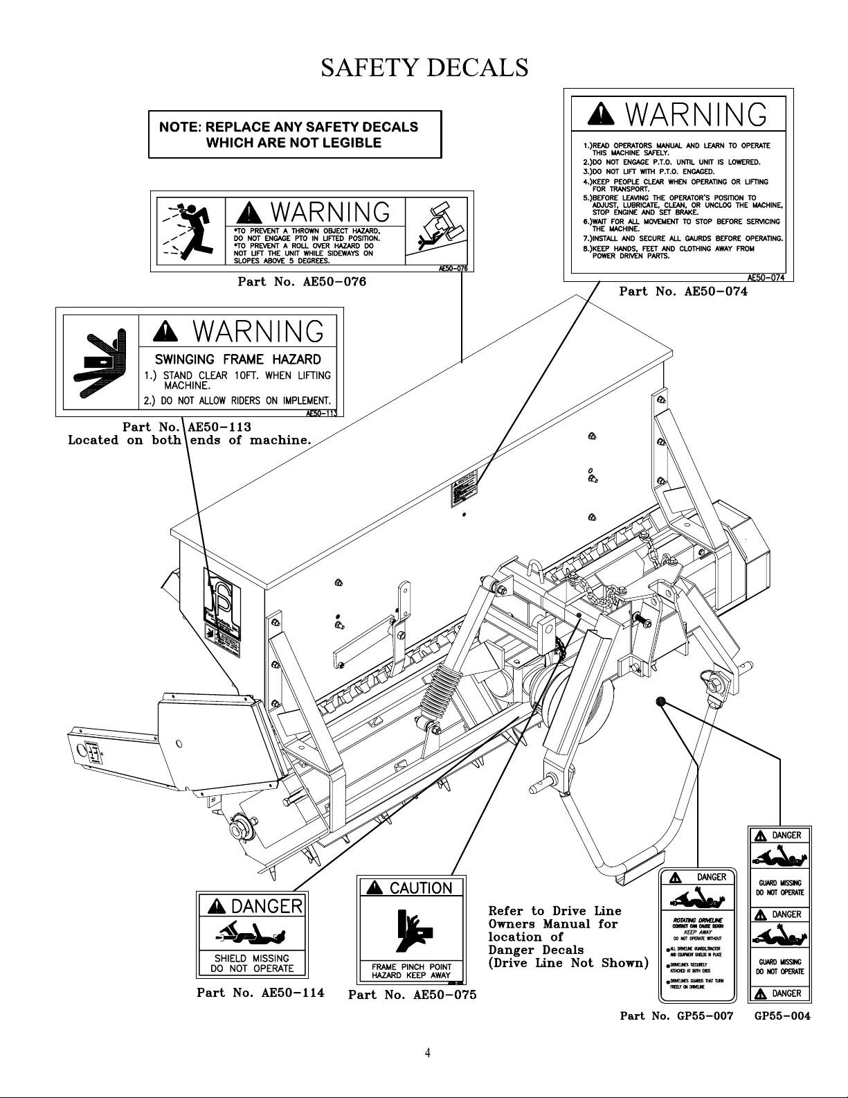
SAFETY DECALS ..........................................................................................................................4
OPERATION SAFETY ...................................................................................................................5
OPERATOR INSTRUCTIONS - General .......................................................................................6
How The Swing Hitch Operates (Prior To Hitching To Tractor) .................................................6
Adjusting The Hitch To A Tractor ...............................................................................................7
Tine Depth With Roller Floating ..................................................................................................7
Tine Depth With Roller Pinned ....................................................................................................7
Transporting The Unit ..................................................................................................................8
From Lift Position To Operating ..................................................................................................8
From Operating To Lift Position ..................................................................................................8
Do Not Operate In Reverse...........................................................................................................8
Roller Scraper Usage ....................................................................................................................8
Tine Wear Limit............................................................................................................................8
Trial Run.......................................................................................................................................8
OPERATOR INSTRUCTIONS – Seeder ........................................................................................9
Seed Flow Control ........................................................................................................................9
Seeder Drive Control ....................................................................................................................9
Emptying The Hopper ................................................................................................................10
Unclogging Seed Tubes..............................................................................................................10
PRE-OPERATION CHECK LIST.................................................................................................10
MAINTENANCE SAFETY...........................................................................................................10
ROUTINE MAINTENANCE ........................................................................................................10
SE-60 ROTOR SHAFT SERVICE INSTRUCTIONS...................................................................12
Rotor Shaft Removal ..................................................................................................................12
Rotor Shaft Disassembly ............................................................................................................13
Rotor Hub Disassembly ..............................................................................................................13
Rotor Hub Re-Assembly.............................................................................................................14
Rotor Shaft Re-Assembly ...........................................................................................................14
Rotor Shaft Installation...............................................................................................................16
WARRANTY INFORMATION ....................................................................................................18
SE60 HITCH ..................................................................................................................................19
SE60 MAIN FRAME.....................................................................................................................21
SE60 ROTOR SHAFT ...................................................................................................................23
SE60 DRIVE LINE ........................................................................................................................24
SE60 ROLLER...............................................................................................................................25
SE60 RAKE ...................................................................................................................................26
SE60 SEEDER HOPPER MOUNTING ........................................................................................27
SE60 SEEDER DRIVE (Ground) ..................................................................................................28
SE60 SEEDER DRIVE (Electric) ..................................................................................................30
SE60 WIRING HARNESS ............................................................................................................31
SEED HOPPER PARTS LIST.......................................................................................................32
SEED HOPPER..............................................................................................................................33
SEEDA-vator Specifications ..........................................................................................................34

3
SAFETY SYMBOLS
This is a standard safety alert symbol meaning ATTENTION ! BECOME
ALERT ! YOUR SAFETY IS INVOLVED !
CAUTION Indicates hazardous situation, injury may
occur, used to alert against carelessness.
WARNING Indicates potentially hazardous situation.
Death or serious injury may occur if
proper procedures are not followed.
DANGER Indicates most hazardous situation. Death
or serious injury will occur if proper pro-
cedures are not followed.

5
OPERATION SAFETY
x Your Safety Is Always First! Familiarize yourself with the safety symbols and de-
cals on pages 3 and 4.
x All operators should read and understand the following sections of this manual
prior to adjusting, maintaining, hitching to, or operating the SEEDA-vator:
OPERATION SAFETY, OPERATOR INSTRUCTIONS, PRE-OPERATION
CHECKS, MAINTENANCE SAFETY, ROUTINE MAINTENANCE.
x In addition, remove and read the drive line safety and maintenance manual taped to
the drive line shield. After reading the drive line manual, place it inside this manual
for reference.
x For the safety and instruction of all operators, keep this manual stored in the tube pro-
vided on the SEEDA-vator at all times.
x Never attempt to adjust, maintain, or remove debris from this machine while the trac-
tor engine is running.
x After operating, always disengage the power take off and switch the engine off prior
to dismounting from the tractor or other power source and approaching the unit.
x Prior to starting, always inspect operating area for any hazards such as large rocks,
steep slopes, low tree branches or wires. Flag objects difficult to see such as irriga-
tion heads and water meters.
x Instruct all people in the work area to stay clear of the unit.
x Perform all pre-operation checks (page 10) prior to start up.
x Never engage the power take off while the rotors are off the ground. Always disen-
gage the power take off before lifting the unit. High-speed rotors create a flying ob-
ject hazard when they are lowered to the ground.
x Consult your tractor Operator's Manual regarding operation on slopes. Do not lift the
unit while the tractor is moving (or parked) sideways on slopes above 5q. The swing
hitch may allow the unit to swing to the downhill side and cause the tractor to roll
over. On slopes from 5qto 15qalways aim the tractor uphill before lifting the unit.
We do not recommend the unit being used on slopes above 15q.
x Use extreme care and maintain moderate ground speed when transporting or operat-
ing on slopes, over rough surfaces, or close to trees ditches and fences.
x Only operate during daylight hours or with good artificial light.
x The unit is not equipped for highway use. Be careful of traffic when operating near
or crossing roadways.
6
OPERATOR INSTRUCTIONS - General
x The SE-60 SEEDA-vator is designed to attach to a tractor with a category one three
point hitch, 540 PTO, and a minimum of 30 horsepower. However, the tractor must
have a lift capacity of 1950 lbs. at a distance of 24” to the rear of the lower lift points
to handle the unit loaded with 6.7 cu. ft. of 40#/cu. ft. seed.
x Before hitching to the unit familiarize yourself with all of the tractors control func-
tions. Be prepared to stop the tractor movement, PTO operation, and the engine
quickly in an emergency.
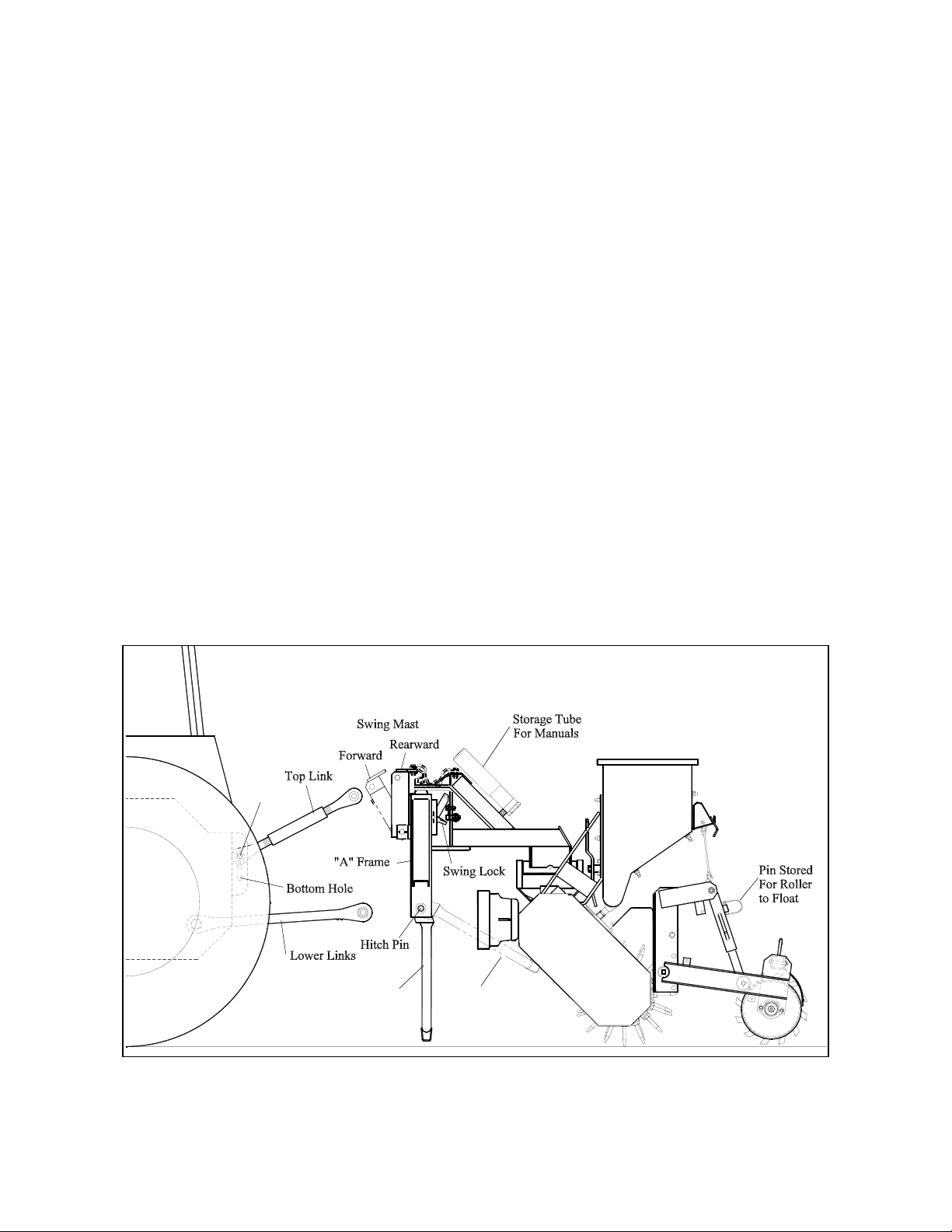
How The Swing Hitch Operates (Prior To Hitching To Tractor)
With the swing stand lowered and the swing mast rearward to disengage the swing lock,
grasp the hitch pins and rotate the “A” frame to simulate operation in a sharp turn. Re-
lease the hitch pins and slowly pull the swing mast forward as it would be pulled by the
top link during lifting. Notice how one mast chain tightens causing the “A” frame and
unit to realign as the compressed lock link spring engages the swing lock. Now push the
swing mast rearward against the lock link tab to disengage the swing lock and loosen the
chains to allow sharp turns again. This demonstrates how the top link of the tractor lift
system switches the unit between the trail and lift modes.
7RS+ROH
6ZLQJ 6WDQG
'RZQ
6ZLQJ 6WDQG
8S
Figure 1. Swing Hitch Operation
7
Adjusting The Hitch To A Tractor
(See Fig. 1 - Tractor and Unit on flat, hard surface with swing stand down and roller in
float position).
A category 1 hitch tractor is required with the lower links stabilized. With the unit swing
stand lowered connect the lower lift links to the “A” Frame Hitch Pins and top link to the
swing mast with the tractor end in the top hole. Push the lift control lever on the tractor to
the completely lowered position. Lengthen the adjustable top link until the swing mast
closes tight against the “A” Frame and the swing stand is lifted just clear of the ground.
This causes the combined weight of the unit and the tractor hitch components to be trans-
ferred to the tines. This extended top link also causes the unit to tilt backwards when lift-
ing allowing gravity to assist the mast chains in aligning the unit with the tractor.
Tine Depth With Roller Floating
With the roller in the float position, the tine depth is dependent on the relationship of
forward speed to PTO speed. [Tine depth is increased by lowering the forward speed
and/or increasing PTO (engine) speed.] The tines would usually penetrate 2” to 3 ½”
deep which causes more surface tillage than shallower tine depths. This arrangement
would most likely be used when seeding in existing turf or hard crusty bare soils. Since
the seed drops ahead of the tines, very few are buried too deep.
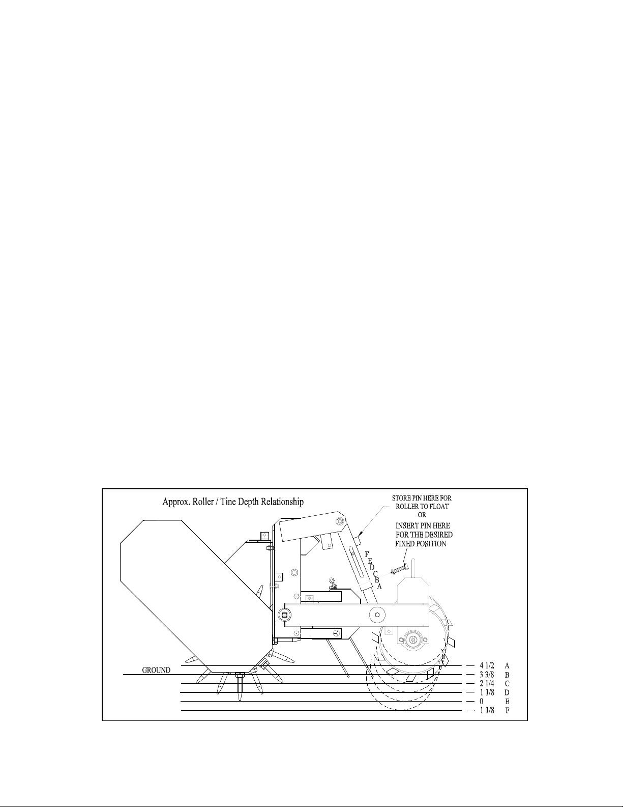
Tine Depth With Roller Pinned
With the roller pinned in various fixed positions, the tine depth is more precisely con-
trolled as shown in Figure 2. Extending the top link longer, which tilts the unit back-
wards, can reduce the actual tine depth in each pinned position. An advantage of tilting
backwards is that gravity assists the mast chains in aligning the unit with the tractor dur-
ing lifting. A pinned roller arrangement is usually used on soft bare soils where deep
tines running would cover the surrounding seed too deep.
Figure 2. Roller & Tine Depth Relationship

8
Transporting The Unit
As previously stated, an extended top link to tilt the unit backwards helps to align it with
the tractor during lifting. However, the backward tilt increases the potential for damage
to the unit on trailer ramps. To avoid damage without having to change the length of the
top link, move the tractor end of the top link from the top hole to the bottom hole. This
will tilt the unit forward for more clearance when lifted. Not changing the top link length
will save time at the next job site. On steep ramps it may also require the roller to be
pinned in the highest position for more clearance.
From Lift Position To Operating
When lowering for operation, lower slowly until the tines touch the ground. Then swiftly
push the lift control lever on the tractor to the completely lowered position to instantly
unlock the hitch. This is especially true when lowering the unit in a sharp turn. Failure
to do this may cause the swing hitch not to unlock, resulting in damage to the machine
and/or turf damage. In the event the unit should fail to unlock for trail mode, stop the
tractor and repeat the lowering procedure.
From Operating To Lift Position
WARNING: When operating diagonally downhill or transversely (sideways) on a
hillside slope above 5qthe mast chains will not swing the unit uphill to center and lock
on the tractor when the unit is lifted. Occasionally the unit will swing farther to the
downhill side of the tractor creating the hazard of tractor roll over. If the tractor ever
seems unstable, immediately lower the hitch and steer the tractor uphill or on a more
level surface where it will center and lock when lifted.
Do Not Operate In Reverse
Do not back the tractor up with the unit touching the ground. Always disengage the
PTO, raise the unit, back to desired location and then lower the machine and engage the
PTO.
Roller Scraper Usage
Generally the roller scrapers are only used when the ground does not have rocks, roots,
construction debris, etc that would clog and stop the rollers from turning.
Tine Wear Limit
Replace tines before the hex shoulder wears down to the extent the 15/16 deep tine
socket will not grip for removal.
Trial Run
The geometry of tractor lift linkages varies, and a trial run over uneven ground is recom-
mended. Ideally the swing lock will not engage when operating over the crown of a hill
and the tractor hitch is always free to float upward at all times. The tines should clear
curbs etc., when lifted. Refer to the pre-operation checklist prior to trial run.
9
OPERATOR INSTRUCTIONS – Seeder
The Gandy Seeder is equipped with a ground or electric driven fluted rotor that feeds seed to a
precision mated stainless hopper bottom and slide with adjustable holes at each of the 22 outlet
spouts.
CALIBRATION
TROUGH
HAIRPIN COTTER
SEED TUBE PIN
SEED DEFLECTOR
SEED TUBES
FLUTED ROTOR
SPOUT PLATE
RETAINING CLIPS
SPOUT PLATE
ROTOR SHIELD
TRASH SHIELD
HOPPER BOTTOM
SLIDE SUPPORT
SLIDE
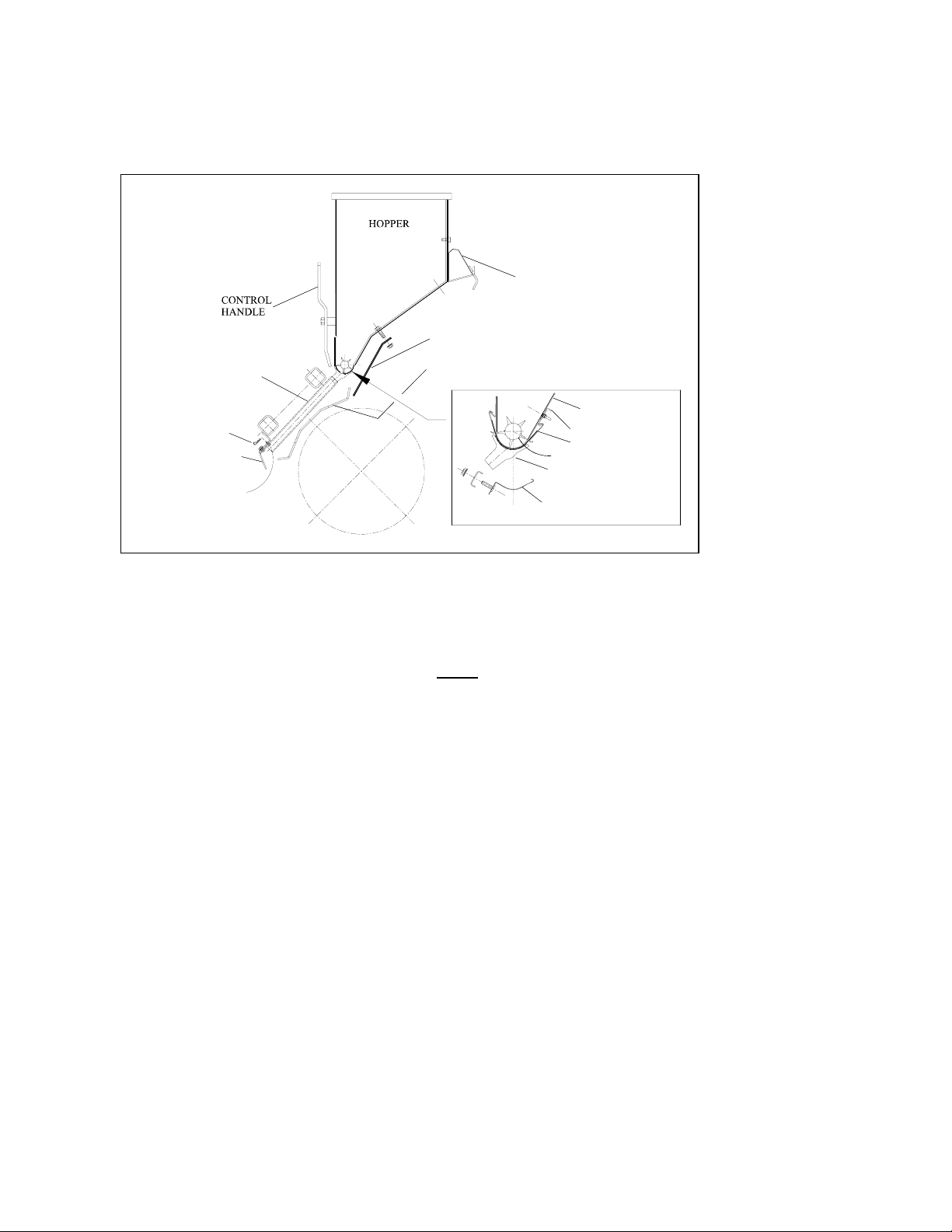
Figure 3. Seeder
Seed Flow Control
The flow rate is controlled by a cam gauge that varies the size of the adjustable holes.
The seed flow is instantly turned off or on by closing and opening the hopper bottom holes with
the control handle on the right front of the hopper. NOTE: Fragile seeds may be damaged if
the electric or ground drive continues to turn the fluted rotor for very long with the flow
turned off.
The flow is gradually stopped or started by stopping or starting the rotation of the fluted rotor
while leaving the control handle in the open position. When the rotor is stopped, the seed con-
tained in the fluted rotor section above the adjustable holes will flow until the section is emptied.
When the rotor starts again, the seed won’t flow until the next fluted rotor section with seed ro-
tates over the adjustable holes.
Seeder Drive Control
On electric drive units the flow control rotor is stopped and started with a remote control switch
at the tractor seat.
On ground drive units (in conjunction with the roller) the fluted rotor stops when the SEEDA-
vator is lifted and starts when it is lowered. Also, the roller drive is provided with a clutch for
stopping the fluted rotor to allow tillage without seeding. Read decal on shield at right end of
roller (see page 28, item 24).

10
Emptying The Hopper
With the control lever and cam wide open, rotate the fluted rotor and catch the seed in the
calibration trough or on a plastic sheet. On ground driven hoppers, disengage roller clutch
(see page 29, item 24) then turn fluted rotor with a 5/8” socket, extension, and wrench on left
end of hopper.
Unclogging Seed Tubes
Remove the hairpin cotters holding the clogged tube and the tubes on either side then
feed the clogged tube up through the framework. Only remove the seed deflector for ac-
cess to the four tubes beneath the gearbox mount. (Refer to routine maintenance section
regarding more extensive cleaning).
PRE-OPERATION CHECK LIST
(With the SEEDA-vator lowered and the tractor engine switched off...)
x Replace any safety decals that are not legible.
x Be sure that the implement is hitched to the tractor properly with all pins in place.
x Pin the swing stand in the up position (see Fig. 1).
x WARNING:Be sure the driveline is correctly assembled. (The end stenciled
as the tractor end is connected to the tractor and not to the SEEDA-vator). Check to see
that the end yokes are locked to the tractor PTO and gearbox shafts. Drive shields must turn
freely on the driveline.
x See that all shields are correctly installed.
x Remove any items from seed hopper that would damage rotors or clog seed tubes.
x Remove any debris caught in the rotors.
x Check gearbox oil level before first operation and every 200 hours of operation thereafter.
(Refer to routine maintenance section.)
MAINTENANCE SAFETY
x Never attempt to clean, adjust, lubricate or perform any maintenance on the SEEDA-vator
while the tractor engine is running.
x SAFETY BLOCKS should be used to support the SEEDA-vator when in the raised position
during service.
x Lower the swing stand when unhitching from the tractor.
x When installing tines, performing any rotor shaft service, or removing debris from the rotors,
ensure that the rotor shaft does not rotate because a serious pinch injury could occur.
ROUTINE MAINTENANCE
x Check gearbox oil level before first operation and every 200 hours of operation thereafter.
With frame level, remove oil level plug on front left side of gearbox using 5/16” allen
wrench. If required, add 90w-gear oil through level plug until it appears at level plug. Re-
place plug securely.

11
x Grease drive line parts after the number hours use as shown in the above illustration.
x The hitch flex joints at the top of the “A” frame and above the gearbox (see page 19) should
be lubricated before first operation and weekly thereafter.
x After the first two hours of operation tighten all tines to 210-ft. lbs. Check for loose tines
daily.
x When replacing lost or worn tines use the 15/16” extra deep socket furnished in the extra tine
bag (additional sockets are available. Order # AE60T003).
x CHECK BELT TENSION after 4 hrs. of operation and every 40 hrs. thereafter. Also,
tighten belts if shaft hesitation is noticed during operation. Refer to decal on end of seed
hopper. Be sure to re-install belt shield after servicing.
x Use the applicable parts break down illustration pp.19-34 for maintenance, removal, and as-
sembly instructions.
x The SEEDA-vator shaft and rotor bearings are sealed and permanently lubricated requiring
no routine maintenance.
x Inside the hopper place a few drops of light oil weekly between the ends of the fluted roller
and the plastic bearings. Do not over oil.
x NEVER apply oil or spray lubricant to hopper bottom or slide.
x Extensive cleaning of the seeder hopper bottom, slide and spout plate (Fig. 3)
A. Remove the seed deflector and all of the seed tubes.
B. Remove the Trash Shield.
C. Remove spout plate retaining clips, cam gauge, and spout plate assembly.
D. Carefully note how the slide supports assemble to the hopper bottom and how they are
shifted endwise to control the clearance between the slide and hopper bottom. The clear-
ance is set at the factory and fixed with self-tapping screws into the hopper bottom. After
removing the screws, nuts, and plastic washers, the slide supports shift to the left to re-
move the slide.
E. Clean all components and wipe with a dry cloth. Do not apply oil or spray lubricants.
F. Re-assemble components in reverse order.
CAUTION
BE SURE ALL SAFETY SHIELDS ARE INSTALLED PRIOR TO RETURNING THIS
MACHINE TO SERVICE.

12
APPROX.
20
FIG. 4 FIG. 5
SE-60 ROTOR SHAFT SERVICE INSTRUCTIONS
(Clean the unit thoroughly with a pressure washer)
Rotor Shaft Removal
1. Hook hoist to mast chains (Fig. 4). WARNING:The hoist and extra chain or strap required
must be rated @ 2000 lbs. (or higher) capacity.
2. Lift unit to fold swing stand in up position.
3. Lower unit to move roller into fully extended position and pin.
4. Chain the Rake Assembly in up position (not shown).
5. Lift unit until rotor shaft is approximately 20” off the floor with the roller supporting the rear end
(Fig. 5)
6. Place Jack Stands under the Rotor Shaft Assembly for added safety. Locate stands between the 1st and
2nd Rotors from each end. Lower unit until Rotor Shaft contacts both stands. Keep hoist connected to
mast chains with very little slack.
7. Remove Belt Cover and Skid Shoe (see pages 21 & 22 in parts section).
8. Loosen Belt Idler & remove Belts.
9. On the opposite end of shaft from pulley, remove 3 of 4 bolts from bearing flanges (see Fig 12).
10. Remove all
4 bolts
from
bearing
flanges at
center
bearing
support.
11. Loosen the
3 nuts at
the top of
the center
bearing
support,
approx. 2
turns each.
12. Remove 3 of 4 nuts from bearing flanges at pulley end.
13. Lift Unit to remove Stands.
14. Lower unit until tines rest on floor (Fig. 4 – Less Belt Cover).
15. Remove remaining bolt from Step 9 and nut from Step 12.
16. Lift unit so tines are 1/4” above the floor then pull rotor shaft towards pulley end until bolts clear holes
in frame. NOTE: ROTATION OF SHAFT MAY BE NECESSARY FOR BOLTS TO CLEAR.
17. Lift unit high enough to allow shaft assembly to be rolled out for repair.
13
Rotor Shaft Disassembly
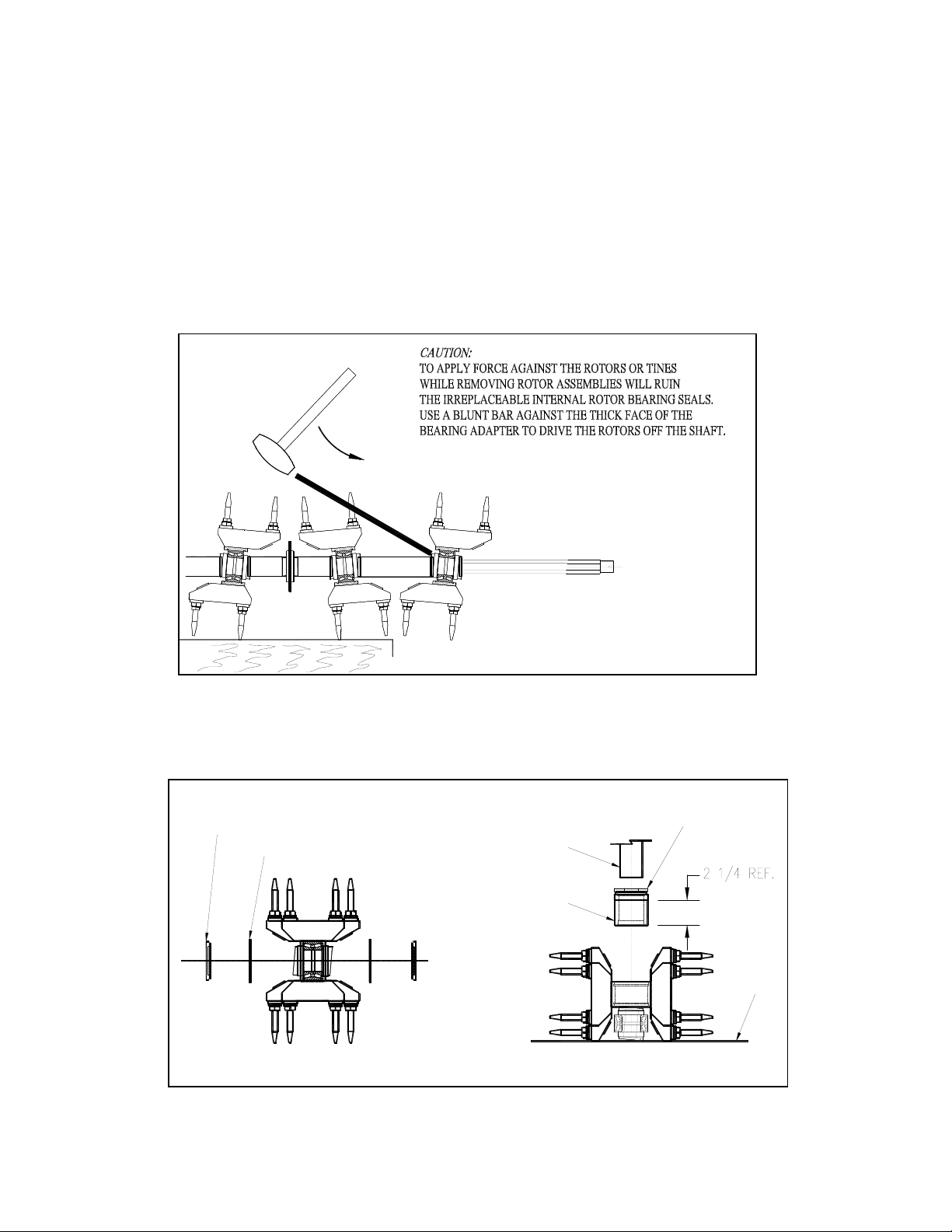
1. Remove the 1-1/8" hex jam nut from the shaft end nearest to the damaged component.
2. Only remove the rotors and spacers required to reach the damaged component. Wipe the shaft
clean before each rotor is removed. Each rotor bearing has two separate cones with a hex
bore adapter pressed in each. Each cone is held in position by an internal grease seal, which
allows the cones to be moved apart slightly. When they are moved apart any dirt allowed
inside the hex adapters can fall between the cones and contaminate the bearing. If the cones
are forced apart the internal seals become ruined and irreplaceable.
3. Clean and inspect parts as they are removed and set aside in their order of removal to simplify
re-assembly.
Rotor Hub Disassembly
1. With a pry bar remove the external seals (Figure 7) on both sides. Generally, seals are
damaged and are not reused.
STEP 3
EXTERNAL SEAL - STEP 1
SNAP RING - STEP 2 PRESS
RAM
PRESS TOOL
AE60T007
TOOL CAP
AE60T008
PRESS
TABLE
2. Remove the snap rings on both sides.
3. Press used bearing and adapter assembly out.
Figure 7.
Figure 6. Rotor Shaft Disassembly
14
Fi
g
ure 9. Timin
g
Mar
k
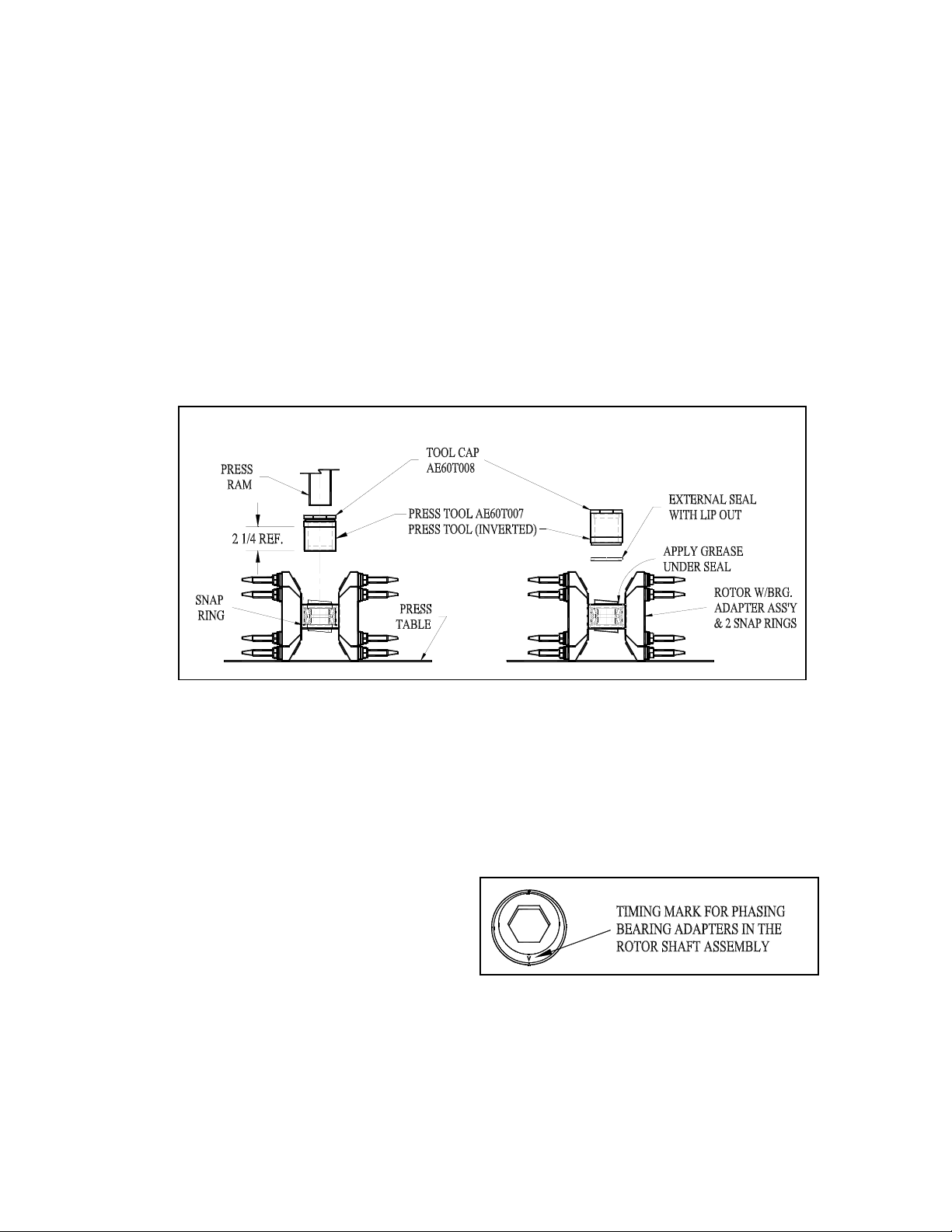
Rotor Hub Re-Assembly
(keep all components clean to prevent bearing contamination)
1. Install internal snap ring in one side of rotor hub. Be sure snap rings expand full depth into
grooves.
2. Press new bearing and adapter assembly down tight against snap ring as shown in Fig. 8.
If bearing is loose in hub the rotor should be replaced.
3. Install snap ring in other end.
4. Apply a ribbon of general-purpose grease between the snap ring ID and bearing adapter OD
on both ends of the rotor hub.
5. With the press tool inverted to fit the external seals, press the seals in both ends of the rotor
with the lips out. Wipe off excess grease. Be sure seals are not bent or cut and are seated
firmly. If the seals are not tight, use a hammer and punch to stake the hub faces at
about 90
q
intervals.
Rotor Shaft Re-Assembly
(Read this section thoroughly before beginning)
CAUTION: IF THE BEARING ADAPTERS ARE NOT PRECISELY TIMED 180
DEGREES APART IN EACH ROTOR AND ALIGNED BETWEEN ROTORS, SERIOUS
DAMAGE WILL RESULT.
1. Rotate the adapters in each rotor so
the timing marks (See Figures 9, 10 &
11) are phased 180 degrees apart with
hex bores aligned.
2. Use marker pen to assist with
aligning timing marks between rotors.
Mark two rotor shaft flats 180 degrees
apart next to the threaded end (See Figure 10). The marked flats would have to
align with the timing marks on any rotors not removed during servicing.
Fi
g
ure 8.

15
Fi
g
ure 11. Rotor Sha
f
t Assembl
y
3. Install the required components in the sequence shown in Figure 11, double checking
the timing mark locations and spacer lengths (see following table) as each rotor is
installed.
SPACER LENGTH PART NO.
A 3 51/64” AE24-027
B 7 1/4” AE24-011
C 3 9/16” AE24-028
D 3 19/64” AE24-029
CAUTION: CLEAN THE ROTOR SHAFT THOROUGHLY REMOVING ANY BURRS
THAT WOULD KEEP THE ROTOR ASSEMBLIES FROM SLIDING ON FREELY. IF A
BEARING ADAPTER JAMS, THE INTERNAL BEARING SEAL COULD BE FORCED
OUT AND IT IS NOT REPLACEABLE.
Figure 10.
63$&(5
5(9 2/9 ('9 ,(:2)
%5 * $' $37(5 )$&(
7,0,1* 0$5 .
21%5 * $'$37(5
0$5.6+$)7)/$76
q$3$5 7

16
NOTE: THE SPACERS MUST BE FULLY SEATED IN EACH ADAPTER
COUNTERBORE BEFORE TIGHTENING. DO NOT FORGET TO PLACE THE
BEARING STAMPINGS ON EACH OF THE SHAFT BEARINGS DURING
REASSEMBLY. ALSO, THE 3/8" CARRIAGE BOLTS SHOULD BE PLACED IN THE
BEARING STAMPINGS ON THE DRIVE END OF THE SHAFT BEFORE THE PULLEY
IS REPLACED.
4. Replace the 1-1/8" hex jam nut and rotate each rotor occasionally as the nut is
torqued to 350 ft-lbs. If any rotor locks up, the bearing adapters in the rotor are
probably not phased 180 degrees apart or the spacers are not fully seated.
Rotor Shaft Installation
(with 2000 lb. rated hoist connected to mast chains)
1. Roll Rotor Shaft Assembly into position under frame bearing holes with pulley on drive end.
2. Carefully lower unit in small increments while keeping both bearing flanges on the side of the
frame end plates and center bearing support as illustrated. Note that the center bearing sup-
port is loose against the frame and can be tilted for alignment. Never assemble with the
bearing flanges separated around a Frame End or the Center Bearing Support.
3. Note that as the frame
ends and center bearing
support are carefully
lowered down beside
each pair of bearing
flanges it is necessary
to push the unit away
from the pulley end.
This allows the frame
end to pass the carriage
bolts sticking through
both bearing flanges
next to the pulley.
4. When the frame ends align with the carriage bolt holes and the bearing flanges, pull the unit
toward the pulley end to assemble nuts on carriage bolts.
5. Install bolts and nuts in center bearing support and other end plate being careful to align car-
riage bolt shoulders with the square holes in bearing flanges (hand tighten).
6. Lift unit until Rotor Shaft is approximately 20” off the floor (See Fig. 5).
7. Place Jack Stands under the Rotor Shaft Assembly for added safety. As during Shaft re-
moval, locate stands between the 1st and 2nd rotors from each end and lower unit until Rotor
Shaft contacts both stands. Keep hoist connected to mast chains with slight tension.
8. Tighten all bearing flange bolts 30-35 Ft-Lbs.
9. Tighten 3 bolts connecting center bearing support to frame 50-55 Ft. Lbs.
Figure 12. Rotor Shaft Re-assembly

17
10. Install and tighten drive belts. (Refer to decal on end of seed hopper)
Tighten both bolts in belt idler bracket 50-55 Ft. Lbs.
11. Install Skid Shoe and tighten bolts 30-35 Ft. Lbs.
12. Install Belt Cover and tighten bolts 8-12 Ft. Lbs.
13. Lift unit to remove Jack Stands.
14. Lower unit until force is removed from pins in roller linkages. Remove pins and store in float
position or use hoist to adjust linkages for inserting pins in another desired fixed position
(See Fig. 2, pg. 7).
15. Lift unit as required to lower swing stand.

18
WARRANTY INFORMATION
ONE YEAR LIMITED WARRANTY
FIRST PRODUCTS INC. WARRANTS THIS PRODUCT TO BE FREE OF DEFECTS IN
MATERIALS AND WORKMANSHIP FOR A PERIOD OF TWELVE MONTHS FROM THE
ORIGINAL DELIVERY DATE. THIS WARRANTY DOES NOT COVER PARTS CAUSED TO
BE DEFICIENT DUE TO NORMAL WEAR, MISUSE, ACCIDENTS, OR LACK OF PROPER
MAINTENANCE.
ANY PARTS THOUGHT TO BE DEFECTIVE MUST BE RETURNED TO THE
DEALER/DISTRIBUTOR FOR WARRANTY CONSIDERATION JOINTLY WITH FACTORY
REPRESENTATIVES. A RETURN AUTHORIZATION NUMBER MUST BE OBTAINED
AND CLEARLY MARKED ON ALL PACKAGES OF PARTS REQUIRING RETURN TO THE
FACTORY.
THE OBLIGATION OF FIRST PRODUCTS INC. UNDER THIS WARRANTY SHALL BE
EXCLUSIVELY LIMITED TO REPLACEMENT OF PARTS DETERMINED TO BE
DEFECTIVE BY FIRST PRODUCTS INC. WITH FREIGHT PREPAID. IN NO EVENT SHALL
FIRST PRODUCTS INC. BE LIABLE FOR INDIRECT, INCIDENTAL, OR CONSEQUENTIAL
DAMAGES IN CONNECTION WITH THE USE OF THIS PRODUCT.
FIRST PRODUCTS INC. RESERVES THE RIGHT TO MAKE CHANGES OR ADD
IMPROVEMENTS TO ITS PRODUCTS AT ANY TIME WITHOUT OBLIGATION TO MAKE
SUCH CHANGES OR IMPROVEMENTS ON PRODUCTS SOLD PREVIOUSLY.
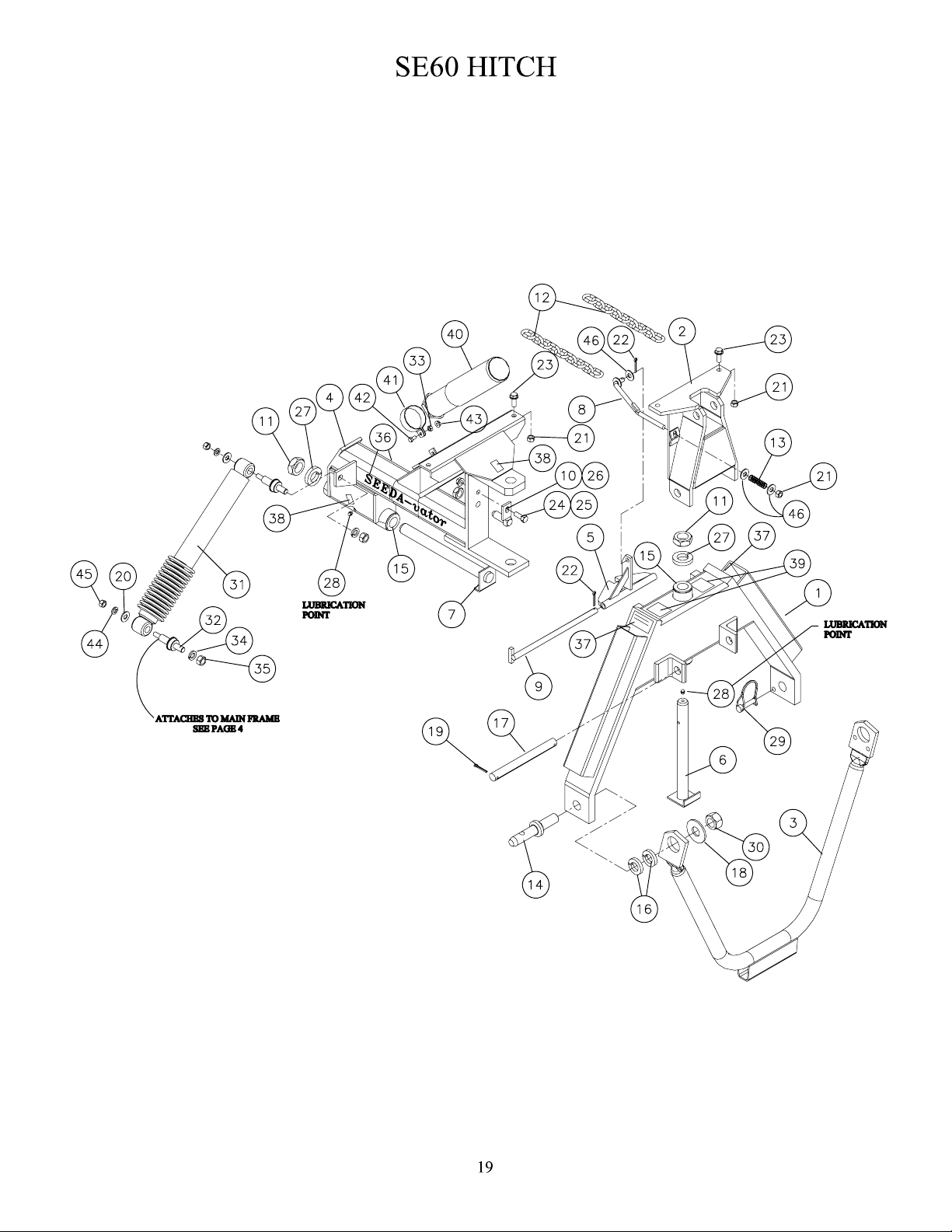
Table of contents
Other First Products Farm Equipment manuals


