First Products UA60T Installation and operation manual

Model - Serial Number
UA60T - 1001 thru ____
Printed in U.S.A.
PB 0616
OPERATOR’S
MANUAL & PARTS LIST
Universal Aera-vator
MODEL UA60T
FIRST PRODUCTS INC.
164 Oakridge Church Road
Tifton, Georgia 31794 U.S.A.
Phone (229) 382-4768
1-800-363-8780
Fax (229) 382-0506
Web: www.1stproducts.com Email: Sales@1stproducts.com
Manual Part #: UA50-109

First Products UA-60T Operator’s Manual
Table of Contents bbbbbbbbbbbbbbbbbbbbbbbbbbbbbbbbbbbbbbbbbbbbbb
1
Operator's Manual
Introduction............................................................. 2
Safety...................................................................... 3
Safety Alert Symbol............................................ 3
Safe Operating Practices..................................... 3
Specifications........................................................ 10
Dimensions ....................................................... 11
Torque Requirements........................................ 11
Product Overview ................................................. 12
Operation .............................................................. 13
Pre-Start............................................................ 13
Operating Instructions....................................... 13
Maintenance.......................................................... 16
Recommended Maintenance Schedule(s)......... 16
Periodic Maintenance ....................................... 17
Check Engine Oil Level................................ 17
Check Air Cleaner......................................... 17
Check Battery Charge................................... 17
Check Hydraulic Oil Level........................... 18
Check Tire Pressure...................................... 18
Check for Loose Hardware........................... 18
Checking Rotor Shaft Tines.......................... 18
Check Condition of Belts.............................. 19
Lubricate Grease Fittings.............................. 19
Check Spark Plugs........................................ 19
Check Fuel Filter........................................... 19
Change Hydraulic System Filter................... 19
Clean Engine................................................. 20
Waste Disposal.......................................20
Motor Oil Disposal ....................................... 20
Battery Disposal............................................ 20
Rotor Shaft Service............................................... 21
Rotor Shaft Disassembly............................... 21
Rotor Hub Disassembly................................ 21
Rotor Hub Re-Assembly............................... 21
Rotor Shaft Re-Assembly............................. 21
WARRANTY INFORMATION .......................... 23
Parts Book
Power Transmission Accessories Group .......... 24
Power Transmission Group .............................. 25
Fuel Tank and Electrical Group........................ 27
Hydraulics Group.............................................. 29
Lift Axle Group ................................................ 31
Covers & Decals Group.................................... 32
Roller Attachment............................................. 33
Brush Attachment (Optional)............................ 34
Aera-vator Shaft................................................ 35
Multi-tine Shaft................................................. 36
Aera-slicer Shaft ............................................... 37
Multi-Spike Shaft.............................................. 38
Coring Shaft...................................................... 39
Lighting Group ................................................. 40
Troubleshooting.................................................... 41
Schematics............................................................ 43
Machine Electrical ........................................ 43
Control Electrical.......................................... 44
Lighting......................................................... 45
Hydraulics..................................................... 46
9
Introduction bbbb bbbbbbbb bbbbbbbbbbbbbbbbbbbbbbbbbbbbbb
2
Introduction
Thank you for purchasing the First Products Aera-
vator. This machine is designed to withstand years
of continuous use and is manufactured by skilled
workers using quality materials. Proper assembly,
maintenance, and safe operating practices will
provide years of satisfactory service.
Using This Manual
This operator’s manual is designed to help
familiarize you with safety, assembly, operation,
adjustments, troubleshooting, and maintenance.
Read this manual and follow the recommendations
to help ensure safe and efficient operation.
Read the warranty located on page 23. Fill in the
required information on the warranty registration
card provided, and return it to the address on the
front of this manual. The warranty registration
must be returned to validate warranty.
To order a new Operator’s and Parts Manual (Part
number UA50-109), contact your authorized dealer
or write to the address listed below in the Owner
Assistance paragraph. Include the model and serial
numbers of your unit. In addition to this, you may
also download a copy of the Operator’s Manual
from our web site: www.1stproducts.com
The information contained within this manual was
current at the time of printing. Some parts may
change slightly to assure you of the best
performance.
Terminology:
“Right” or “Left” as used in this manual is
determined by standing behind the machine and
facing the direction of operation.
Definitions:
NOTE: A special point of information related to its
preceding topic. The author’s intention is that you
read and note this information before continuing.
IMPORTANT: A special point of information that
the author feels you must be aware of before
continuing with the instructions that follow.
Owner Assistance
If customer service or repair parts are required,
contact your First Products dealer. A dealer has
trained personnel, repair parts, and the equipment
needed to service your machine. These parts have
been specifically designed for your Aera-vator and
should only be replaced by genuine First Products
parts.
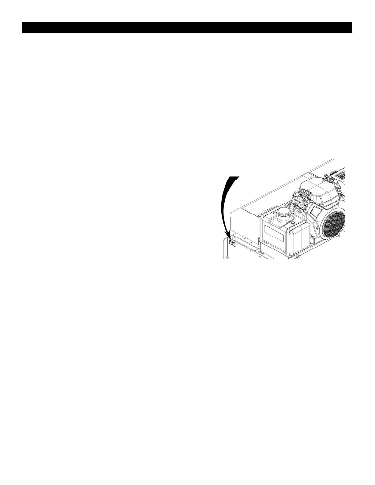
Serial Number Plate
Refer to Figure 1 for the location of your serial
number plate.
Figure 1: Aera-vator Serial Number Location
For prompt service, always use the serial
number and model number when ordering parts
from your First Products dealer. Fill in Model and
serial numbers of each unit you’ve purchased in the
section below. If for any reason you do not
understand any part of this manual or not satisfied
with service you received, discuss the matter with
your dealership service manager. For further
assistance, write to:
First Products, Inc
Attn: Product Support
164 Oakridge Church Road
Tifton, Ga 31794
Date Purchased_____________________________
UA60T Serial No.___________________________
Engine Model No. and Spec. No._______________
Engine Serial No .___________________________
Figure 1. Serial number Plate

First Products UA-60T Operator’s Manual
Safety bbbbbbbbbbbbbbbbbbbbbbbbbbbbbbbbbbbbbbbbbbbbbb
3
Safety
Safety Alert Symbol
This is the safety alert symbol. It means:
ATTENTION! BECOME ALERT! YOUR
SAFETY IS INVOLVED!
DANGER: White lettering / Red background
Indicates an imminently hazardous situation, which,
if not avoided, will result in death or serious injury.
This signal word is limited to the most extreme
situations, typically for machine components that,
for functional purposes, cannot be guarded.
WARNING: Black lettering / Orange background
Indicates a potentially hazardous situation, which, if
not avoided, could result in death or serious injury,
and includes hazards that are exposed when guards
are removed. It may also be used to alert against
unsafe practices.
CAUTION: Black lettering / Yellow background
Indicates potentially hazardous situation, which, if
not avoided, could result in minor or moderate
injury. It may also be used to alert against unsafe
practices.
Safe Operating Practices
Training
Read Operator’s manual and other training
material. If the operator(s) or mechanic(s) can
not read English it is the owner’s responsibility
to explain this material to them.
Become familiar with the safe operation of the
equipment, operator controls and safety signs.
All operators and mechanics should be trained.
Never let children or untrained people operate
or service the equipment. Local regulations
may restrict the age of the operator.
Preparation
Evaluate the terrain to determine if any thing is
needed to properly and safely perform the job.
Wear appropriate clothing including safety
glasses, substantial footwear, long trousers, and
hearing protection. Do not operate with long
hair, loose clothing or jewelry; these could get
tangled in moving parts.
Inspect the area where equipment is to be used
and remove all rocks, toys, sticks, wires, and
other foreign objects which can be thrown by
the machine and may cause personal injury to
the operator or bystanders.

First Products UA-60T Operator’s Manual
Safety bbbb bbbbbbbb bbbbbbbbbbbbbbbbbbbbbbbbbbbbbb
4

First Products UA-60T Operator’s Manual
Safety bbbbbbbbbbbbbbbbbbbbbbbbbbbbbbbbbbbbbbbbbbbbbb
5
Operation
Operate only in daylight or good artificial light,
keeping away from hidden hazards.
Never operate the machine with damaged
guards, shields, or covers. Always have safety
shields, guards, switches and other devices in
place and in proper working condition.
DO NOT change the engine governor setting or
over speed the engine.
Stop engine, wait for all moving parts to stop,
and remove key:
oBefore checking, cleaning or working on the
machine.
oAfter striking a foreign object or abnormal
vibration occurs (inspect the machine for
damage and make repairs before restarting
and operating).
Stop engine, and wait for all moving parts to
stop:
oBefore refueling.
oBefore checking oil levels
NEVER carry passengers. Do not operate the
machine when people, children, or pets are in
the area.
Be alert, slow down and use caution when
making turns. Look behind and to the side
before changing directions.
Do not operate the machine under the influence
of alcohol and drugs.
Use extreme care when loading or unloading the
machine from a trailer or truck.
Use extreme caution when approaching blind
spots, corners, shrubs, trees, or other object that
may obscure vision.

First Products UA-60T Operator’s Manual
Safety bbbb bbbbbbbb bbbbbbbbbbbbbbbbbbbbbbbbbbbbbb
6
Slope Operation
Use Extreme caution when operating and/or
turning on slopes as loss of traction and/or tip-over
could occur. The operator is responsible for safe
operation on slopes.
See the inside of the back cover to determine the
approximate slope angle of the area to be
operated on.
Remove or mark obstacles such as rocks, tree
limbs, etc. from the area. Tall grass can hide
obstacles.
Watch for ditches, holes, rocks, dips, and rises
that change the operating angle, as rough terrain
could overturn the machine.
Always avoid sudden starting or stopping on a
slope. If tires lose traction, turn off aerator and
proceed slowly off the slope.
Operating on wet grass or steep slopes can
cause sliding and loss of control. Wheels
dropping over edges, ditches, steep banks, or
water can cause rollovers, which may result in
serious injury, death, or drowning.
Do Not operate on slopes when grass is
wet.
Do Not operate on slopes greater than 15
degrees.
Do Not operate near drop-offs or near
water.
Reduce speed and use extreme caution on
slopes.
Avoid sudden turns or rapid speed
changes.

First Products UA-60T Operator’s Manual
Safety bbbbbbbbbbbbbbbbbbbbbbbbbbbbbbbbbbbbbbbbbbbbbb
7
Maintenance and Storage
Lift aerator out of ground, stop engine, and
remove key before adjusting, cleaning, or
repairing.
Keep power transmission components (belts,
pump, engine, etc.) free of debris. The debris
can become combustible which may result in a
fire.
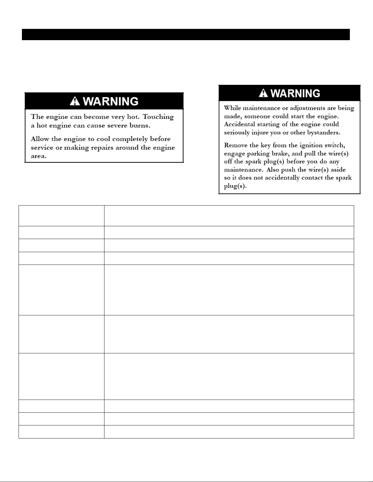
Let engine cool before storing and do not store
near flame or any enclosed area where open
pilot lights or heat appliances are present.
Drain fuel from tank while storing.
Pin the cylinder lock-out bar into place and
carefully release pressure from components with
stored energy.
Never allow untrained personnel to service
machine.
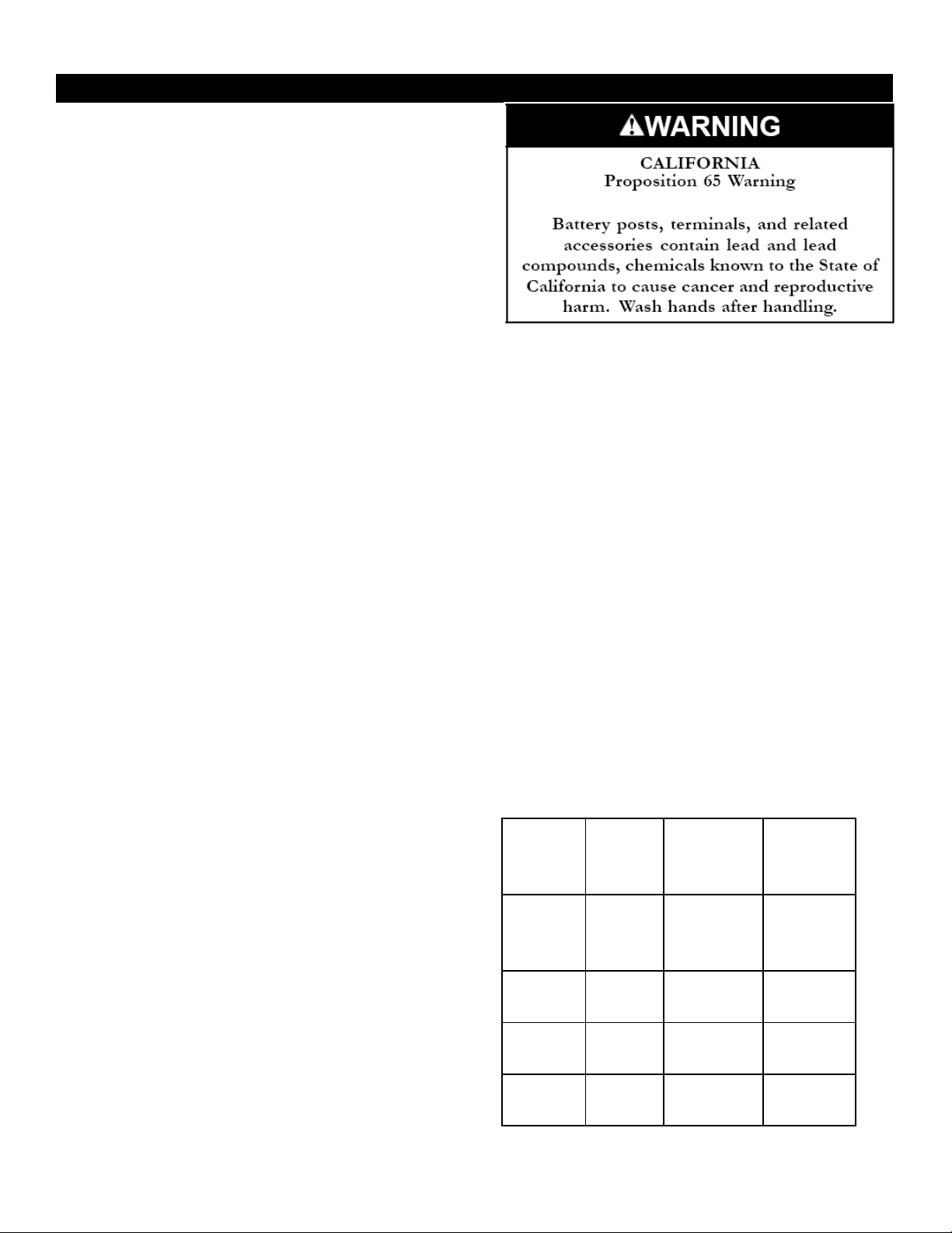
Disconnect the negative terminal cable from the
battery before making any repairs. If battery is
required to be removed, always disconnect the
negative cable first and always connect the
positive first while reinstalling.
Charge battery in an open, well-ventilated area,
away from sparks and flames.
Keep all guards, shields, and all safety devices
in place and in safe working condition.
Check bolts frequently to maintain proper
tightness.
Check belts frequently for proper tensioning and
wear condition.
Check all moving components for worn or
deteriorating components that could create a
hazard.
All replacement parts must be the same as or
equivalent to the parts supplied as original
equipment.
Check fluid levels daily during operation. If
fluids are needed, fill with the correct fluids
specified.
Inspect all hydraulic hoses and adapters daily
for leaks or defects.
When brushes are attached, Anti-tip leg must be
extended before disconnecting hitch from tow
vehicle.
Anti-tip Leg
First Products UA-60T Operator’s Manual
Safety bbbb bbbbbbbb bbbbbbbbbbbbbbbbbbbbbbbbbbbbbb
8
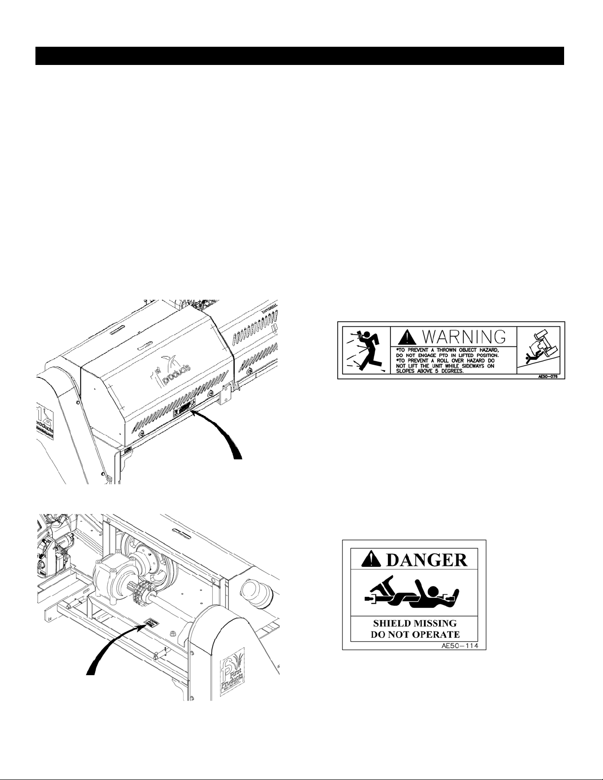
Safety and Instructional Decals
Keep all safety signs legible. Remove all
grease, dirt and debris from safety signs and
instructional labels.
Replace all worn, damaged, or missing safety
signs.
When replacement components are installed, be
sure that current safety signs are affixed to the
replaced components.
If an attachment or accessory has been installed,
make sure current safety signs are visible.
New safety signs may be obtained from your
authorized First Products, Inc. equipment dealer or
distributor.
Safety sign may be affixed by peeling off the
backing to expose the adhesive surface. Apply
only to a clean, dry surface. Smooth to remove
any air bubbles.
Familiarize yourself with the following safety
signs and instruction labels. They are critical to
the safe operation of your First Products
machine.
REAR COVER
AE50-076
THROWN OBJECT HAZARD
AE50-114
DANGER HAZARD
UNDER EXPOSED JACK SHAFT
AE50-114
AE50-076

First Products UA-60T Operator’s Manual
Safety bbbbbbbbbbbbbbbbbbbbbbbbbbbbbbbbbbbbbbbbbbbbbb
9
UA50-099
CYLINDER LOCK DECAL
AE50-074
G
ENERAL WARNING DECAL
FRONT COVER

First Products UA-60T Operator’s Manual
Specifications bbbbbbbbbbbbbbbbbbbbbbbbbbbbbbbbbbbbbbbbbbbbbb
10
Specifications
Engine
Engine Specifications: See your Engine
Owner’s Manual
RPM: Full Speed 3400 +/- 100 RPM (No Load)
Idle: 1600 RPM
Fuel System
Capacity: 5 gal. (18.9 L)
Type of Fuel: Regular unleaded gasoline, 87
octane or higher
Fuel filter: In-line 40 Micron
Honda P/N :16910-Z6L-003
Electrical System
Charging System: Flywheel Alternator
Charging Capacity: 20 amps
Battery Type, BCI Group U1
Battery Voltage: 12 Volt
Polarity: Negative Ground
Fuses: One 20 amp blade type
Safety System
Transport lock must be used when machine is
hauled from one venue to another
Operator Controls
The operator controls the lifting, lowering,
and aeration from a hand-held control box
with three switches (Figure 3).
The operator accesses the engine controls
via its control panel found opposite its oil
filter side.
oEngine Throttle Control
The throttle is used to control engine speed.
Moving the throttle lever upward will
increase engine speed and moving
downward will decrease engine speed.
oChoke Control
The choke is used to aid in starting a cold
engine. Pulling the choke outward will put
the choke in the “ON” position and pushing
the knob inward, will put the choke in the
“OFF” position. Do Not run a warm engine
with choke in the “ON” position.
oIgnition Switch
The ignition switch is used to start and stop
the engine. The switch has three positions
“OFF”, “RUN” and “START”. Insert key
into switch and rotate clockwise to the
“RUN” position. Rotate clockwise to the
next position to engage the starter (key must
be held against spring pressure in this
Figure 2. Transport Lock
Figure 3. Hand-held Control
First Products UA-60T Operator’s Manual
Specifications bbbbbbbbbbbbbbbbbbbbbbbbbbbbbbbbbbbbbbbbbbbbbb
11
position). The PTO switch must be in the off
position to start the engine.
oAuto Throttle Handle
With the Auto throttle handle in the down
position (locked position) the engine’s RPM
will increase as the machine is lowered into
the ground. As the unit is lifted the engine
will return to idle.
The auto throttle can be disengaged when
auto throttling is not required by raising the
auto throttle handle into the unlocked
position.
oHour Meter
The hour meter is connected to the ignition
switch to record the amount of run time on
the unit. The hour meter will work while the
engine is operating.
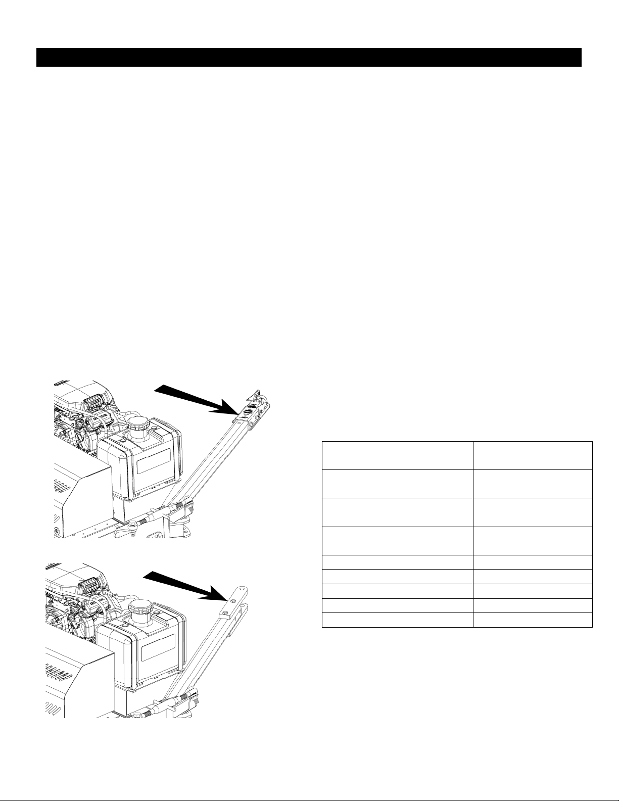
Transport Options
The UA-60T can be transported by using its
standard 2” ball coupler or its draw bar option.
Hydraulic Lift System
Hydraulic Pump: ½ Gal/Min Fixed
Displacement Gear Pump
Hydraulic Cylinder: 2” Bore with 8” Stroke
Hydraulic Oil Type: A68 Hydraulic Oil.
Hydraulic Oil Capacity: 1.7 gal. (6.4 L)
Tires & Wheels
Tires are 20 ½” on 8” wheels fastened with five
lug nuts on 5 ½” centers.
Tires have highway tread and are 16 ply with a
load rating F.
Dimensions
Overall Width: 95 ½” (Outside of Tires)
Overall Height: 48 ½” (Raised & Level)
Overall Depth: 36” (Tongue Removed)
80” (Back of Fender to
Tongue)
Torque Requirements
Engine Mounting bolts 38-40 ft-lbs
(51 – 56 N-m)
Wheel Lug nuts 90-95 ft-lbs
(122-129 N-m)
Tines in Rotor
Aera-vator Shaft 210-215 ft-lbs
(284- 291 N-m)
Implement frame to Tractor
mount bolts 111 – 115 ft-lbs
(150 -156 N-m)
1/4 UNC Standard Bolts 11 ft-lbs (14 N-m)
5/16 UNC Standard Bolts 21 ft-lbs (28 N-m)
3/8 UNC Standard Bolts 38 ft-lbs (51 N-m)
1/2 UNC Standard Bolts 85 ft-lbs (120 N-m)
5/8 UNC Standard Bolts 175 ft-lbs (235 N-m)
Figure 4. Standard 2” Ball Coupler
Figure 5. Draw Bar Option

First Products UA-60T Operator’s Manual
Operation bbbbbbbbbbbbbbbbbbbbbbbbbbbbbbbbbbbbbbbbbbbbbb
12
Product Overview
Before operating the UA-60T, it is necessary to
understand how the machine works and why it
functions in such manner.
The machine uses an engine to power two power
transmission components: Hydraulic pump &
Electric clutch. The hydraulic pump is used to lift
and lower the machine. The electric clutch engages
the rotor shaft and causes the tines to vibrate.
Hydraulic Circuit
When the engine is on, the pump is continuously
circulating hydraulic oil from the reservoir, to the
pump, to the valve block, and back to the reservoir.
When the operator presses the momentary switch
for the raise or lower function on the hand-held
controller (Figure 3) the fluid entering the valve
block is diverted to the cylinder causing the
machine to raise or lower. See Figures 6 and 7.
Automatic Throttle Activation
The engine throttle is tied to a cable-spring
assembly which is pulled when the lift cylinder is
extended, Figure 8. When the machine is lowered,
the cylinder extends; this action pivots the bracket
hooked to the spring and cable assembly. As the
cable is pulled, the engine speed is increased.
Likewise, when the machine is lifted, the cable is
retracted by a spring on the engine.
Aeration Mechanism
The UA-60T is designed to start aeration when the
electric clutch is turned on. With the Auto Throttle
Handle, Figure 8, position down, the engine will
automatically throttle up as it lowers to the ground.
Once the tines start to touch the ground, the electric
clutch may be engaged to start the patented
vibrating tines. To lower the machine without
throttling up the engine, simply lift the pivot catch
handle, Figure 8, and allow the stud to travel in the
slot while the machine lowers to the ground.
Figure 6. Hydraulic Circuit
Figure 7. Hydraulics
Fi
g
ure 8. Automatic Throttle Mechanis
m

First Products UA-60T Operator’s Manual
Operation bbbbbbbbbbbbbbbbbbbbbbbbbbbbbbbbbbbbbbbbbbbbbb
13
Operation
Note: The left and right sides of the machine are
defined as standing behind it and facing the
direction of operation.
Pre-Start
Fill fuel tank, for best results use clean, fresh
regular unleaded gasoline with an octane rating of
87 or higher.
Do Not add oil to gasoline.
Do Not overfill fuel tank. Never fill fuel tank so
that the fuel level rises above a level that is ½ inch
(13 mm) below the bottom of the filler to allow for
fuel expansion and prevent fuel spillage.
Make sure the operator understands the controls,
their locations, their functions, and their safety
requirements.
Refer to the Maintenance section and perform all
necessary inspection and maintenance steps.
Operating Instructions
Hitching Machine and Set-up
The UA-60T can be hitched to any working vehicle
desired for operation. The standard 2 inch ball
coupler is utilized for most applications. The
optional draw-bar attachment can be used in
situations where the 2” ball coupler is not feasible,
such as small utility tractors.
Once the machine is connected, the hand-held
control switch must be installed. Located under the
fuel tank, a socket receives the plug from the
control switch. Uncoil the switch and use ties as
necessary to ensure the cord does not make contact
with the vehicle in turns or the ground upon
lowering to the ground.
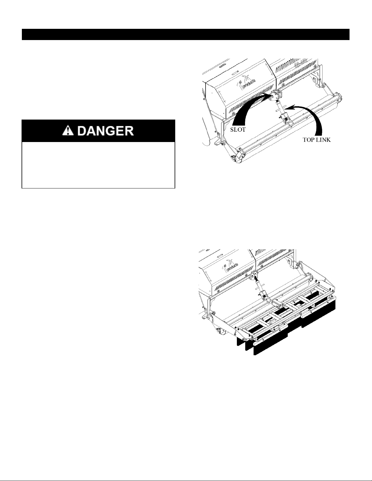
Leveling Aera-vator for Operation
The UA-60T is equipped with a top link connected
to the sway bar on the right side. This top link is
adjusted in or out to level the aerator during
operation.
1. With the machine hitched at the worksite, start
the engine.
2. Lift the Auto Throttle Handle to disengage the
throttle, Figure 8, and use the control box to
lower the machine to the ground.
3. Rotate the top link as necessary to level the
machine, Figure 9.
4. Raise the machine and engage the Auto Throttle
Handle for use.
Start the Engine
1. Before starting the engine, if the machine is in
the lowered position. The Auto Throttle
Handle, Figure 8, must be lifted to disengage
the throttle.
2. On a cold engine, pull the choke knob outward
into the “ON” position.
3. On a warm engine, leave the choke in the
“OFF” position.
4. Turn ignition switch to the “START” position.
Release the switch as soon as the engine starts.
IMPORTANT: Do NOT crank the engine
continuously for more than ten seconds at a
time. If the engine does not start, allow 60
second cool-down period between starting
attempts. Failure to follow these guidelines
can burn out the starter motor.
5. If the engine is difficult to start, the throttle can
be used momentarily. As soon as the engine
starts, cut the throttle down to the idle position.
6. If the choke is in the “ON” position, gradually
return choke to the “OFF” position as the engine
warms up.
Figure
9.
Leveling Aera
-
vator
First Products UA-60T Operator’s Manual
Operation bbbbbbbbbbbbbbbbbbbbbbbbbbbbbbbbbbbbbbbbbbbbbb
14
Aeration
With the engine running and the machine fully
lifted:
1. Ensure the Auto Throttle Handle is lowered
back into position to allow the throttle cable to
be pulled when machine is lowered to ground.
2. Tow machine to starting point on worksite and
lower using hand-held control switch, Figure 3.
3. Adjust the ground speed accordingly. Slow
down to allow tines to penetrate deeper. The
chain hanging on the left side of the machine is
a visual indicator for depth. If the chain is
touching the turf, full depth is achieved.
4. Press the control switch to lift the machine when
desired.
Operating the Attachments
The UA-60T is equipped to have both a solid roller
and a brush fastened to the frame. Attachments can
be seen in further detail in the parts list portion of
this manual.
The roller is seen is Figure 10. It is made to
primarily float using a slot located on the top
bracket on the frame. When down pressure from
the roller is desired, the top link is adjusted to lower
the roller downward until down pressure is achieved
and the pin is at the top of the slot.
The brush is shown in Figure 11. It is fastened to
the frame in a three-point hitch configuration to
allow smooth floatation. The brush easily locks
into place for transportation by simply lifting the
brush to the top of its range. The brush can be
modified to various widths and configurations to
conform to the user’s needs.
The movement of the rotors on the machine is
dangerous. Contact with rotor shaft can
cause serious injury or death. Do NOT put
hands or feet in the working area of the rotor
shaft while activated.
Figure 10. Roller Attachment
Figure 11. Brush Attachment
First Products UA-60T Operator’s Manual
Operation bbbbbbbbbbbbbbbbbbbbbbbbbbbbbbbbbbbbbbbbbbbbbb
15
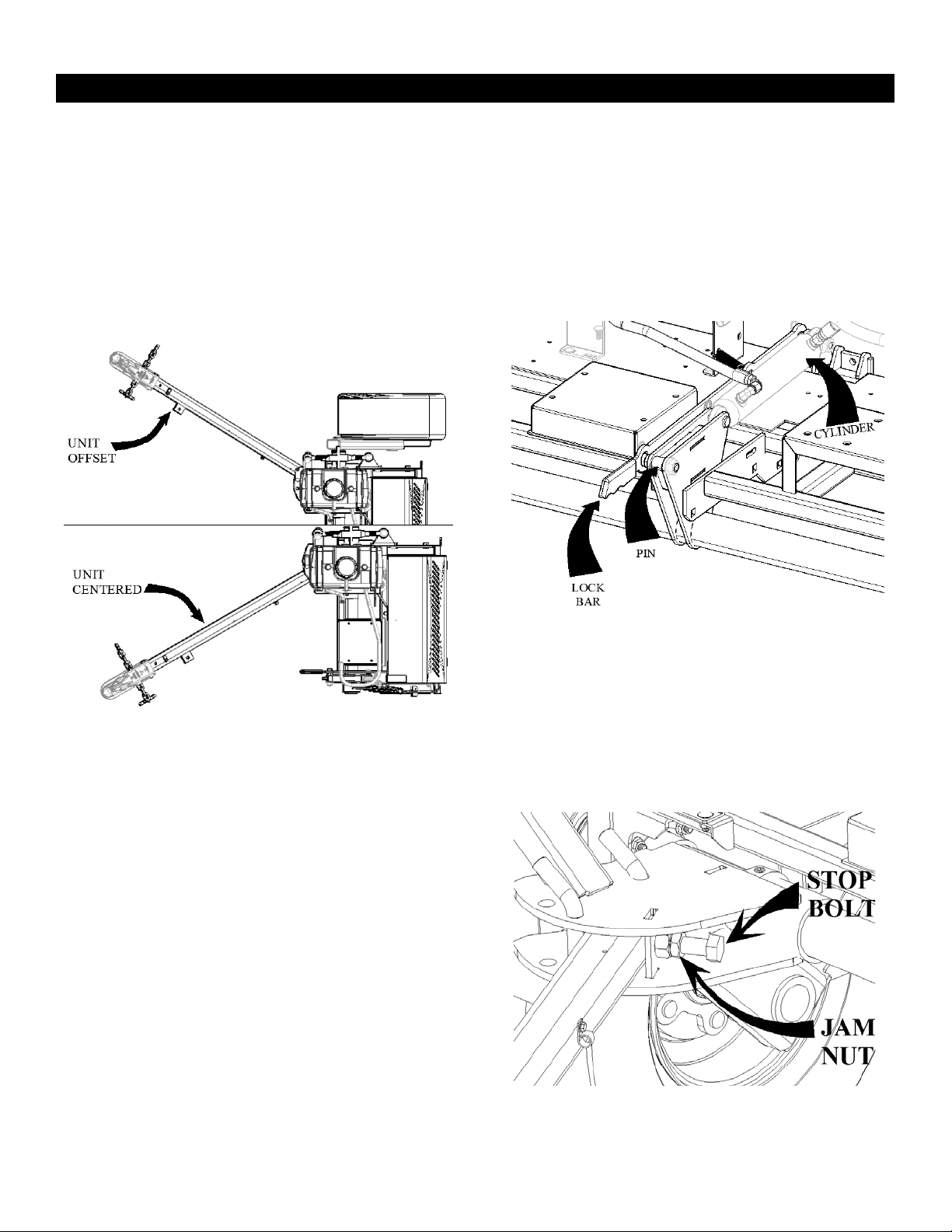
Offsetting unit
The unit may be operated either directly behind the
tow vehicle or offset to the side of the vehicle. The
unit can be offset by changing the tongue position,
Figure 12. The offset can be adjusted between the
two outer positions shown by aligning the holes in
the tongue with either of the sets of holes in the
Tongue Swivel.
Transporting unit
Before transporting the UA-60T from one location
to another, the red handled Cylinder Lock-Bar
located by the lift cylinder must be pinned to the
cylinder to prevent the machine from gradually
leaking down over time. The red handled Cylinder
lock-bar is seen in Figure 13.
The tongue of the unit should also be locked to its
centered position, Figure 12, with the stop bolt
being tightened against the tongue and locked into
place with the jam nut, Figure 14. The unit should
only be transported while centered behind the
tow vehicle with the stop bolt tightened.
Figure 12. Offsetting Unit
Figure 13. Cylinder Lock Bar
Figure 14. Stop Bolt Location
First Products UA-60T Operator’s Manual
Maintenance bbbbbbbbbbbbbbbbbbbbbbbbbbbbbbbbbbbbbbbbbbbbbb
16
Maintenance
Recommended Maintenance Schedule(s)
Maintenance Service
Interval Maintenance Procedure
After the first 5 hours Change the engine oil.
After the first 100 hours Check the Wheel Lug nuts.
After the first 250 hours Change the hydraulic filter.
Before Each use or daily
Check the engine oil level.
Check for loose hardware
Check for loose tines.
Clean debris off Engine exhaust and rotor shaft
Every 40 hours
Check Hydraulic Oil Level.
Check Tire pressures.
Check the condition of the belts.
Every 50 hours
Service the air cleaner. (May need more often under severe conditions. See
Engine Owner’s Manual for additional information)
Change the Engine oil and Oil filter.
Grease Lift Axle at Bushings (3 places).
Every 100 hours Check belts for wear & tear. Clean around belts and pulleys as necessary.
Monthly Check the battery charge.
Yearly Check the wheel lug nuts.
First Products UA-60T Operator’s Manual
Maintenance bbbbbbbbbbbbbbbbbbbbbbbbbbbbbbbbbbbbbbbbbbbbbb
17
Periodic Maintenance
Check Engine Oil Level
Service Interval: Before each use or daily
1. Engine must be level for checking oil. After
starting the engine, disengage the throttle from
the pivoting axle by lifting the Auto Throttle
Handle (Figure 8) while lowering the machine
to the ground.
2. Turn engine off.
3. Check with cool engine.
4. Clean area around dipstick. Remove dipstick
and wipe oil off. Reinsert the dipstick. Remove
the dipstick and read the oil level.
5. If the oil level is low, fill to the “FULL” mark
on the dipstick, Use oil as specified in the
Engine Owner’s Manual. Do Not over-fill.
Important: Do Not operate the engine with the
oil level below the “LOW” (or “ADD”) mark on
the dipstick, or over the “FULL” mark.
Check Air Cleaner
Service Interval: Every 50 hours-Service
the air cleaner. (may need more often
under severe conditions. See the Engine
Owner’s Manual for additional
information.)
1. Stop engine, wait for all moving parts to stop,
and remove key.
2. See Engine Owner’s Manual for cleaning
instructions.
Check Battery Charge
Service Interval: Monthly
Allowing batteries to stand for an extended period
of time without recharging them will result in
reduced performance and service life. To preserve
optimum battery performance and life, recharge
batteries in storage when the open circuit voltage
drops to 12.4 volts.
NOTE: To prevent damage due to freezing,
battery should be fully charged before putting away
for winter storage.
Check the voltage of the battery with a digital
voltmeter. Locate the voltage reading of the battery
in the table and charge the battery for the
recommended time interval to bring the charge up
to a full charge of 12.6 volts or greater.
Important: Make sure the negative battery
cables are disconnected and the battery charger
used for charging the battery has an output of 16
volts and 7 amps or less to avoid damaging the
battery (see chart for recommended charger
settings).
Voltage
Reading Percent
Charge
Maximum
Charger
Setting
Charging
Level
12.6 or
greater 100% 16 volts/7
amps
No
Charging
Required
12.4 -
12.6 75-
100% 16 volts/7
amps 30
Minutes
12.2 -
12.4 50-75% 16 volts/7
amps 1 Hour
12.0 –
12.2 25-50% 16 volts/7
amps 2 Hours
First Products UA-60T Operator’s Manual
Maintenance bbbbbbbbbbbbbbbbbbbbbbbbbbbbbbbbbbbbbbbbbbbbbb
18
11.7-
12.0 0-25% 14.4
volts/4
amps 3 Hours
11.7 or
less 0% 14.4 volts/
2 amps 6 Hours
or More
Check Hydraulic Oil Level
Service Interval: Every 40 hours
Hydraulic Oil Level
1. Stop engine and wait for all moving parts to
stop. Make sure unit is on a level surface.
2. The hydraulic reservoir is located under the rear
left cover of the machine. Unscrew the cap and
clean the dipstick.
3. Reinsert the dipstick. Do not screw into place.
Remove the dipstick and read the oil level.
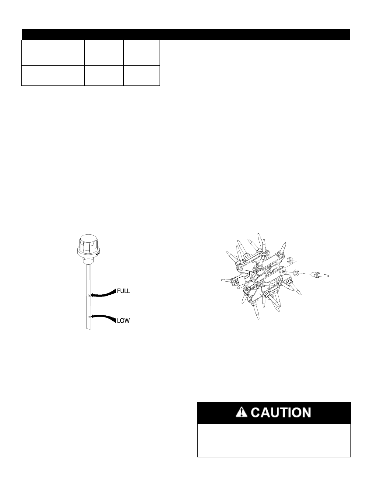
4. If the oil level is low, fill to the “FULL” mark,
Figure 15. Do Not overfill.
Figure 15. Dipstick Markings
5. Use only A68 Hydraulic Oil or appropriate
substitute.
Check Tire Pressure
Service Interval: Every 40 hours
1. Stop engine and wait for all moving parts to
stop.
2. Check tire pressure and make any necessary
adjustments.
Check for Loose Hardware
Service Interval: Before each use or daily
1. Stop engine, wait for all moving parts to stop,
and remove key.
2. Visually inspect machine for any loose
hardware or any other possible problem.
Tighten hardware or correct the problem before
operating.
Checking Rotor Shaft Tines
Service Interval: Before each use or daily
1. Ensure the rotor shaft is off the ground with the
lift cylinder completely retracted and engage red
handled cylinder lock bar.
2. Stop engine, wait for all moving parts to stop,
and remove key.
3. Clean rotor and shaft free from debris.
4. Inspect for loose of broken tines.
Figure 16. Rotor
5. Tines are assembled as shown in Figure 16. The
tines are removed and installed using an extra
deep impact socket (AE60T003), provided with
shaft. Torque tines to 210 ft-lbs.
For safety reasons, each maintenance
operation must be performed with the
machine off and key removed.
First Products UA-60T Operator’s Manual
Maintenance bbbbbbbbbbbbbbbbbbbbbbbbbbbbbbbbbbbbbbbbbbbbbb
19
Check Condition of Belts
Service Interval: Every 40 hours
1. Stop engine, wait for all moving parts to stop,
and remove key.
2. Check under all covers to check belts going to
pump, gearbox, and rotor shaft.
3. Replace any belts in need of repair.
Lubricate Grease Fittings
Service Interval: Every 50 hours
1. Stop engine, wait for all moving parts to stop,
and remove key.
2. Lubricate all three fittings located on the lift
axle at each bushing. Refer to parts breakdown
of lift axle for assistance.
Check Spark Plugs
Service Interval: Every 160 hours
Remove spark plugs, check condition and reset
gaps, or replace with new plugs. See Engine
Owner’s Manual.
Check Fuel Filter
Service Interval: As required
A fuel filter is installed between the tank and the
engine. Replace when necessary.
Change Hydraulic System Filter
Service Interval: After the first 250 hours,
Yearly thereafter
1. Stop engine, wait for all moving parts to stop,
and remove key.
2. With the lift cylinder fully retracted, use the red
handled lock-out bar to pin the cylinder into
place and prevent the machine from leaking
down.
3. Carefully clean area around filter. It is
important that no dirt or contamination enters
the hydraulic system.
4. Use proper tools to slowly remove the hose and
fittings from the in-line filter. Pay special
attention to the direction the filter is oriented.
5. Install new filter using proper tools and torque
on adapters and fittings.
6. Operate machine for several minutes
7. Check oil level.
Note: Do Not change hydraulic system’s oil
(except for what can be drained when changing
filter), unless it is required due to contamination or
overheating. Changing oil unnecessarily could
contaminate hydraulic system.
Failure to lock out the lift cylinder while
performing maintenance on the hydraulic
system can result in serious injury.
Hydraulics fluids escaping under pressure
can penetrate skin and cause injury.
Keep your body and hands away from
pin hole leaks.
Hydraulics Couplers, hydraulic lines/valves,
and hydraulic fluids may be hot. If you
contact hot components you may be burned.
Wear gloves when operating the
hydraulic couplers.
Allow the machine to cool before
touching hydraulic components.
Do not touch hydraulic spills.
Table of contents
Other First Products Farm Equipment manuals


