Ritchie CattleMaster Series User manual

Installation Instructions for
CattleMaster Series
Fountains
Congratulations, you have just purchased the finest watering fountain on the
market. This unit is built to give you excellent service when properly installed
and maintained. Please follow instructions carefully. Read and understand all
instructions before installing.
Ritchie Industries, Inc.
800-747-0222 Part # 17873
www.ritchiefount.com August 13, 2022
@RitchieWaterers

CattleMaster Series
Installation Instructions
A. Location - Installing the fountain in a location that offers protection from the wind will enhance the
performance of the fountain. Livestock will tend to gather in this protected area, enticing them to drink more.
Access panel should be opposite of prevailing winter wind to give additional protection to the supply line.
B. Water Supply Line - Horizontal underground water line should be sized to account for pressure drop,
relating to distance, and placed one foot below frost line. A one-inch vertical supply pipe is recommended. A
shut-off valve should be installed under fountain to allow for easier servicing. For optimum serviceability, a stop
and waste valve can be installed below frost level to drain water when unit is not in use. Vertical supply line must
be centered in riser tube to provide an air space between the line and frozen ground outside of tube. Flush water
supply line thoroughly before connection to fountain. Water supplies with foreign material such as sand, rust, etc.
may require a filter to keep fountain valve working properly.
C. Electric Supply – It is generally most cost effective to run your electrical supply line at the same time you are
trenching for your water supply.
Item
No.
Description
Watts
Amps
Item
No.
Description
Watts
Amps
18248
CM480 120V
548W
4.6A@120V
18251
CM480 240V
648W
2.7A@240V
18235
CM840 120V
1048W
8.7A@120V
18243
CM840 240V
948W
4A@240V
18700
CM10T 120V
1048W
8.7A@120V
18701
CM10T 240V
948W
4A@240V
18252
CM1440 120V
1298W
10.8A@120V
18255
CM1440 240V
948W
4A@240V
CattleMaster Series Instruction Manual
1
August 13, 2022

D. Riser Tube - Install a riser tube and extend it at least one foot below frost line or
down to horizontal underground water line. For optimum water line protection, use
the 12” diameter insulated Ritchie Thermal Tube, part numbers and sizes are shown
to the right. Tube opening must be kept clear.
NOTE: The supply line touching the riser tube is the most common cause of
the supply line freezing. Do not surround the supply line with insulation,
wood, or other foreign material. Any foreign material in the tube may cause
frost to migrate to the supply line causing it to freeze.
E. Mounting Platform - A concrete platform must be provided for all fountains. Use a minimum of 4” thick,
(6” recommended thickness), large enough to accommodate fountain, and additional 4” step (on top of the
platform) extending 18” out from each side of the unit. This will protect the unit from manure handling
equipment, as well as discouraging animals from defecating in the fountain. Extending the platform provides
animals a place to stand while drinking, consider the size of your animals when determining the dimensions of
your platform. The concrete step and platform should slope away from the fountain for drainage and should be
flush with the top of the thermal tube. A rough broom finish to concrete surface provides better footing for
livestock.
F. Preparing the Bottom - Apply the provided foam weather stripping to the bottom of the unit, along the
outside edge of the fountain.
G. Anchoring Fountain - CattleMaster Fountains have mounting pockets molded into the base. Use of Ritchie
part #16555, stainless steel anchor bolts (not included), is recommended.
Once you have verified the positioning of the fountain, drill, install, and tighten down anchor bolts. Use the large
washers provided to hold unit down. Tighten hold down anchors tight, but do not over tighten as this could
damage the plastic feet. NOTE: Do not drill holes for anchors before location can be verified with unit.
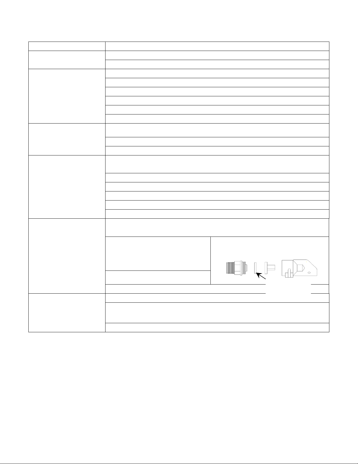
H. Hose Connection – Remove side panels and cover. Pull the bottom of the hose to the shut-off valve at the top
of the concrete. Leaving enough slack to be able to pull the valve assembly from the standpipe, cut hose to proper
length. Slip hose end on barb fitting and attached with hose clamp.
Hose should not touch insulation or outside surface of fountain.
Clamps and fittings are furnished to secure connections.
I. Cable Heater – Uncoil cable heater and loop around the valve.
Attach the remaining part of the cable heater to the water supply, as
far down the riser tube as possible with the cable twist ties provided.
This heater is watertight but should not be immersed in water. Heater
may cross over itself but should not be tightened at those locations.
CAUTION: Installation must not cause any strain on
heater wiring connections. Avoid heater damage caused
by hot spots due to its leads lying close to each other.
Also, do not wrap additional insulation around heater.
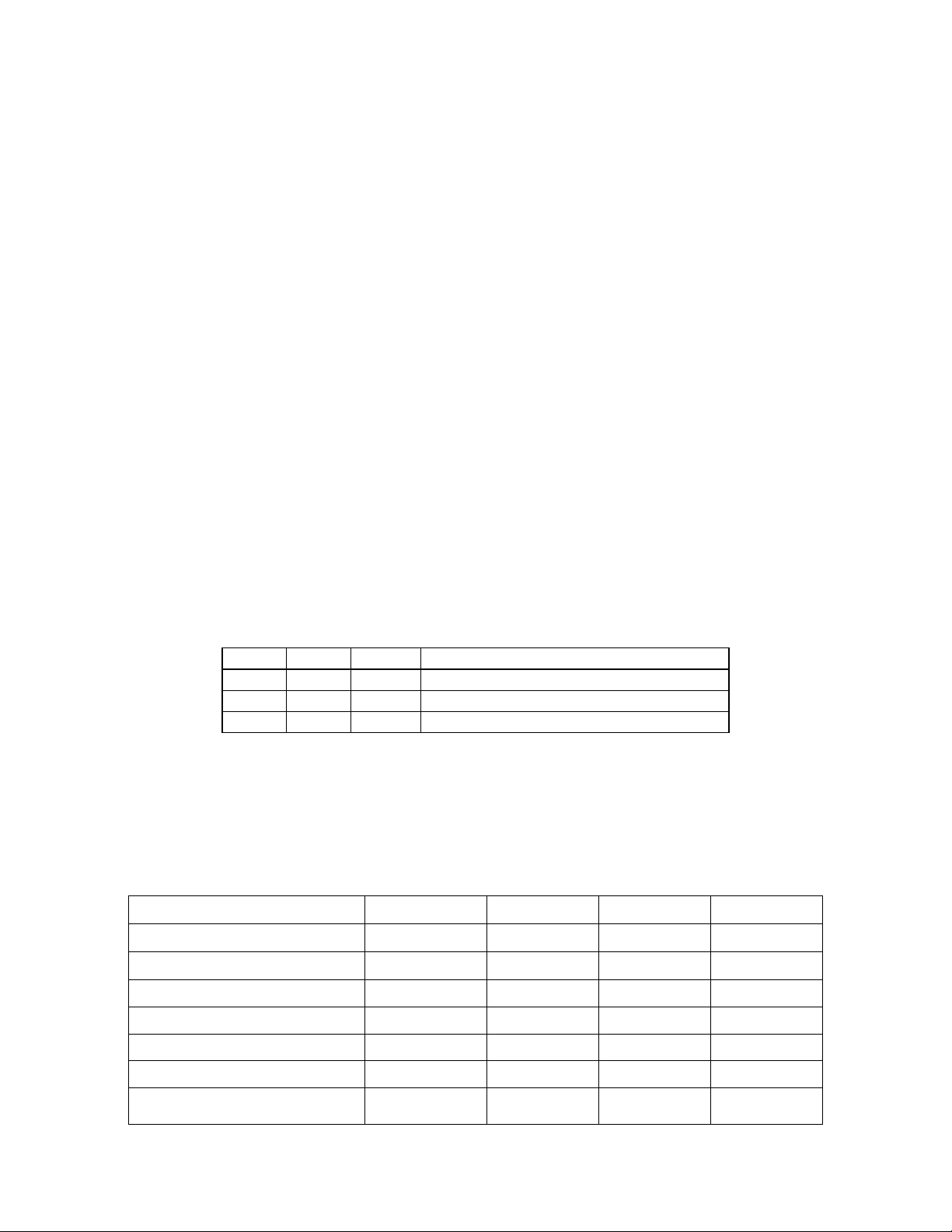
Ritchie Thermal Tube
Part # Description
18158
1’ Top Section
16417
2’ Top Section
16612
4’ Top Section
16416
2’ Extension
CattleMaster Series Instruction Manual
2
August 13, 2022

J. Electrical Connection - The electrical installation should be made and maintained by a qualified electrician
conforming to national and local codes. A means for disconnection must be incorporated in the fixed wiring in
accordance with the wiring rules. A suitable fuse or circuit breaker with properly sized wire must protect the 3-
wire power to the fountain. For wiring connections, see wiring diagram.
WARNING: ANY ELECTRICAL SERVICE MUST BE INSTALLED AND MAINTAINED BY A
QUALIFIED ELECTRICIAN.
WARNING: DISCONNECT POWER IF THE WATER SUPPLY IS TO BE SHUT OFF FOR AN
EXTENDED AMOUNT OF TIME. FAILURE TO TURN OFF POWER CAN RESULT IN DAMAGE TO
THE WATERING FOUNTAIN.
WARNING: THIS INSTALLATION MUST BE MADE AND MAINTAINED IN STRICT CONFORMITY
WITH NATIONAL/LOCAL PLUMBING CODES AND NATIONAL/LOCAL ELECTRICAL CODES
(CSA IN CANADA). THE APPLICABLE PROVISIONS OF THESE CODES TAKE PRECEDENT.
FAILURE TO MAKE AND MAINTAIN ALL INSTALLATIONS PROPERLY MAY RESULT IN LOSS
OF LIVESTOCK, PERSONAL INJURY, OR DEATH.
NOTE: National/Local electrical codes may require livestock waterers installed in feedlots in open
feeding area to be grounded by a separate stranded copper grounding conductor or at least no.6 AWG
terminating at a point where the branch circuit receives its supply. Check with local inspecting
authorities.
K. Fenwal Thermostat – The adjustable range of the Fenwal Thermostat is from 0o
F (-18oC) to 100oF (38oC). The thermostat is not preset at factory.
To adjust the thermostat to the desired temperature, first fill the trough to proper water
level then check the water temperature with a thermometer. The next morning, check
the water temperature again. If the water is warmer than desired, turn the thermostat
down (clockwise). If there is ice forming on the surface of the water, turn the
thermostat up (counterclockwise). Only slight adjustments should be made to the
thermostat at any time. A 1/16 turn on the thermostat will change the water temperature
7o F (4oC). The most economical temperature for the trough is 44oF (7o C).
L. Seal the Base - After the unit is completely installed, apply a bead of caulking around the base of the fountain
to ensure no wind enters through the base of the unit.
NOTE: Sealing the bottom of the unit from cold air is an important aspect of the unit's thermal
performance.
M. Drain Plug – Insert the drain plug firmly into the drain hole in the trough. The plug can be secured by
tightening the wingnut at the center of the plug. Additional 3” casing plug is provided for under unit draining
option. (Plug is required for CattleMaster 840.)
N. Water Seal Drain – Install the small drain plug into the drain hole in the water seal groove around the valve
chamber seal. This plug may be removed during the non-freezing periods to allow the water seal groove to drain.
O. Float Adjustment – Open water-supply shut-off valve, check for and fix any leaks. Adjust float for a water
depth of 2 inches below top of trough or overflow pipe by adjusting the thumbscrew. With the valve functioning
properly and the water level set at the proper level, you may install the valve cover. The water seal groove
CattleMaster Series Instruction Manual
3
August 13, 2022

between the frame and valve cover must be filled with liquid to create a protective seal from cold winter air
getting to the valve.
P. Install Side Access Panel – Once all water line connections have been checked for leaks and electrical hook-
up is complete, the side access door may be installed.
Q. Children should be supervised to ensure that they do not play with the appliance – This appliance is not
intended for use by persons (including children) with reduced physical, sensory, or mental capabilities, or lack of
experience and knowledge, unless they have been given supervision or instructions concerning use of the
appliance by a person responsible for their safety.
R. Cleaning Your Fountain – To clean your watering fountain you will need a good stiff bristled brush.
Remove the cover then brush the water seal groove to remove any build-up then brush the tank. Remove the plug
that is located at the end of the trough to drain out the water and debris. You can shut off the water with the shut-
off valve located under the unit or by holding the float in the up position. After the water and debris has drained
reinstall the plug and let the tank refill. Now is a good time to readjust the float if needed. Reinstall cover and
you are done. Ritchie Valves
Ritchie valves come in two sizes and three pressure ratings – green for high supply line pressure, red for moderate
supply pressure, and white for low-pressure applications. Differences in the size of trough also impacts valve
choice. Although different pressure rated valves may be used in a fountain, each fountain will only accommodate
one size and configuration of valve. Your individual situations may require a change from the standard valve
supplied with your fountain, see your Ritchie Dealer if this is needed.
3/4”
Part #
GPM
Pressure Range
White
16697
33
Low, 5-40 psi (34-275 kPa)
Red
11101
20
Moderate, 40-60 psi (275-414 kPa)
Green
15377
16.5
High, 60-80 psi (414-552 kPa)
NOTE: Maximum inlet water pressure for each valve is shown above. If water pressure is
extremely high, and if the valve does not shut off, a pressure-reducing valve may be needed.
Product Specifications
Product Name
CM480
CM840
CM10T
CM1440
Part # 18248 18235 18700 18252
Drink Height - in/cm
16/41
16/41
25/64
16/41
Width - in/cm
23.5/59.7
23.5/59.7
32/81
23.5/59.7
Length - in/cm
51/129.5
86/218.4
120/305
146/370
Shipping Weight - lbs/kg
90/41
123/56
235/107
186/84
Operating Capacity - gal/liter
20/76
35/133
50/189
60/227
Herd Capacity - head
200 beef,
100 dairy
300 beef,
150 dairy
400 beef,
200 dairy
475 beef,
240 dairy
CattleMaster Series Instruction Manual
4
August 13, 2022

Trouble Shooting
Problem
Solution
Water in Trough Too
Warm
Adjust thermostat to lower temperature
Check to see if thermostat has failed by contacts burning closed
Ice in Trough
Check fuses or circuit breakers
Check all heating elements to make sure they are working and hot
Adjust thermostat to higher temperature
Check for voltage from thermostat output
Check voltage to fountain with and without electrical load
Check that heaters are wired properly
Valve Freezing
Check that cable heater is installed properly and fastened to water supply line and is
working when heaters are hot
Check for missing or damaged insulation
Check for air gaps for wind penetrations
Supply line Freezing
Check that the cable heater is uncoiled and fastened around valve, to supply line
and is working when heaters are hot
Check that supply piping is centered in riser tube
Check that riser tube is free of water and mud that may freeze
Check that flexible hose does not touch side of casing or frame
Check casing for air leaks
Check for air gaps between casing and concrete floor
Valve won’t stop dripping
Check float adjustment. Check for waterlogged float, or float rubbing on side of
valve compartment
Disassemble valve and check for
sand or scale in valve rubber. Also
check valve orifice outlet for wear and
damage. A screen or filter ma
y be
required with sandy or scaly water
Turn valve rubber over and re-
assemble
Check for excessive water system pressure
Low water flow
Check that valve inlet is not plugged or supply hose is not kinked
Check system pressure from supply hose by installing a tee and a pressure gauge
directly in front of the valve to check pressure drop when valve is open. A severe
pressure drop indicates a restriction or undersized supply system.
Check that shutoff valves are fully open
Valve Rubber
3/4” Valve:
CattleMaster Series Instruction Manual
5
August 13, 2022

CattleMaster Series Instruction Manual
6
August 13, 2022

8/16/2021
Wiring-2021.dwg
TDU - Sheet: 1 of 1
WHITE
BLACK
BLACK
BLACK
BLACK
BLACK
BLUE
BLUE
BLUE
BLUE
WHITE
BLACK
WHITE
WHITE
BLACK
BLACK
GREEN
RED
BLACK
BLACK
BLACK
BLACK
BLACK
BLUE
BLUE
BLUE
BLACK
BLUE
BLACK
RED
RED
BLACK
RED
GREEN
CABLE
HEATER
120V
TROUGH HEATER
120V
THERMOSTAT
FENWAL OR DISC
GREEN
GREEN GROUND
WHITE NEUTRAL
BLACK HOT
COMMERCIAL
POWER
WIRING DIAGRAM FOR HEATED UNITS
NOTE: Power cord may be supplied on select units to simplify
installation. Use of a moisture resistant, exterior grade outlet is
recommended in these units. Do not use extension cords.
CABLE
HEATER
240V
TROUGH HEATER
240V
THERMOSTAT
FENWAL OR DISC
WARNING - CHECK NAMEPLATE FOR CORRECT
VOLTAGE. ONLY CONNECT 120VAC TO 120V UNITS.
WIRING DIAGRAM SHOWN WITH 2
HEATERS - QUANTITY MAY VARY
GREEN GROUND
RED - L2
BLACK - L1
COMMERCIAL
POWER
BLACK
BLACK
BLACK
BLACK
L1
L2
120V UNITS - SINGLE PHASE
(3) WIRE CONNECTORS FIELD SUPPLIED
240V UNITS - SINGLE PHASE
(3) WIRE CONNECTORS FIELD SUPPLIED
WARNING - CHECK NAMEPLATE FOR CORRECT
VOLTAGE. ONLY CONNECT 230-240VAC TO 240V UNITS.
WIRING DIAGRAM SHOWN WITH 2
HEATERS - QUANTITY MAY VARY
CattleMaster Series Instruction Manual
7
August 13, 2022

DRAIN ASSEMBLY
PRE-2019 UNITS
CattleMaster 10T
Part # 18700
Item Part # Description Qty . . Item Part # Description Qty
1 18428 CM Cover 1 15 18181 CM Standpipe pkg 1 pkg
2 18349 CM Frame pkg 1 pkg 16 11514 Valve Bracket 3/4" pkg 1 pkg
18350 CM Cover & Frame pkg 1 pkg 17 15377 Green Male Valve 3/4" pkg 1 pkg
3 18698 CM 10T Casing 1 18 18314 Float with Hardware pkg 1 pkg
4 18697 CM 10T Trough 1 pkg 18313 Hardware for Float pkg 1 pkg
5 16562 Access Panel 10"x20" 2 19 18338 CM Drain Plug pkg 1 pkg
6 18147 Access Panel Hardware pkg 2 pkgs 20 17679 CM Bulkhead fitting 2" 1
7 16534 Fenwal Thermostat SS pkg 1 pkg 21 18849 Ritchie 2" Plug pkg 1 pkg
18320 O-Ring Fenwal (6/pkg) 1 pkg 22 18852 CM Drain Assembly w/Plug 1 pkg
18074 Nut Brass Fenwal (6/pkg) 1 pkg NS 12583 Valve Supply Line w/Bracket 1 pkg
8 18266 Frame Bolt & Wshr SS(3/pkg) 1 pkg NS 13830 Cable Htr 120V 48W (1/pkg) 1 pkg
9 18265 Trough Bolt & Nut SS (5/pkg) 1 pkg NS 18333 CM 10T Accessory pkg 1 pkg
10 11419 Heater 120V 250W (1/pkg) 4 pkgs NS 14866 Seal Foam 1/2"x3/4"x10' Roll 2
11 18318 Bolt Down Washer (4/pkg) 2 pkgs
12 17677 Drain Tube 10" 1 18701 CM 10T 240V
13 18653 Ritchie Decal 12" (1/pkg) 1 pkg NS 11403 Heater 240V 300W (1/pkg) 3 pkgs
14 18633 Plug #3 - Water Channel (2/pkg) 1 pkg NS 16424 Cable Htr 240V 48W (1/pkg) 1 pkg
18
17
16
15
19
20
21
22
4
1
2
9
14
8
7
10
3
13
5
611
12
CattleMaster Series Instruction Manual
8
August 13, 2022

DRAIN ASSEMBLY
PRE-2019 UNITS
CattleMaster 1440
Part # 18252
Item Part # Description Qty . . Item Part # Description Qty
118428 CM Cover 1 15 18181 CM Standpipe pkg 1 pkg
218349 CM Frame pkg 1 pkg 16 11514 Valve Bracket 3/4" pkg 1 pkg
18350 CM Cover & Frame pkg 1 pkg 17 15377 Green Male Valve 3/4" pkg 1 pkg
3 18659 CM 1440 Casing 118 18314 Float with Hardware pkg 1 pkg
416791 CM 1440 Trough pkg 1 pkg 18313 Hardware for Float pkg 1 pkg
5 16621 Access Panel 6"x14" 3 19 18338 CM Drain Plug pkg 1 pkg
6 18147 Access Panel Hardware pkg 3 pkgs 20 17679 CM Bulkhead fitting 2" 1
7 16534 Fenwal Thermostat SS pkg 1 pkg 21 18849 Ritchie 2" Plug pkg 1 pkg
18320 O-Ring Fenwal (6/pkg) 1 pkg 22 18852 CM Drain Assembly w/Plug 1 pkg
18074 Nut Brass Fenwal (6/pkg) 1 pkg NS 12583 Valve Supply Line w/Bracket 1 pkg
8 18266 Frame Bolt & Wshr SS(3/pkg) 1 pkg NS 13830 Cable Htr 120V 48W (1/pkg) 1 pkg
9 18265 Trough Bolt & Nut SS (5/pkg) 2 pkgs NS 18333 CM 1440 Accessory pkg 1 pkg
10 11419 Heater 120V 250W (1/pkg) 5 pkgs NS 14866 Seal Foam 1/2"x3/4"x10' Roll 3
11 18318 Bolt Down Washer (4/pkg) 3 pkgs
12 17677 Drain Tube 10" 118255 CM 1440 240V
13 18653 Ritchie Decal 12" (1/pkg) 1 pkg NS 11403 Heater 240V 300W (1/pkg) 3 pkgs
14 18633 Plug #3 - Water Channel (2/pkg) 1 pkg NS 16424 Cable Htr 240V 48W (1/pkg) 1 pkg
17
18
16
15
4
1
2
9
14
8
7
13 5
6
11 3
12
10
20
19
22
21
CattleMaster Series Instruction Manual
9
August 13, 2022

DRAIN ASSEMBLY
PRE-2019 UNITS
CattleMaster 840
Part # 18235
Item Part # Description Qty . . Item Part # Description Qty
1 18428 CM Cover 1 15 18181 CM Standpipe pkg 1 pkg
2 18349 CM Frame pkg 1 pkg 16 11514 Valve Bracket 3/4" pkg 1 pkg
18350 CM Cover & Frame pkg 1 pkg 17 15377 Green Male Valve 3/4" pkg 1 pkg
3 18240 CM 840 Casing 1 18 18314 Float with Hardware pkg 1 pkg
4 16786 CM 840 Trough pkg 1 pkg 18313 Hardware for Float pkg 1 pkg
5 16621 Access Panel 6"x14" 2 19 18338 CM Drain Plug pkg 1 pkg
6 18147 Access Panel Hardware pkg 2 pkgs 20 17679 CM Bulkhead fitting 2" 1
7 16534 Fenwal Thermostat SS pkg 1 pkg 21 18849 Ritchie 2" Plug pkg 1 pkg
18320 O-Ring Fenwal (6/pkg) 1 pkg 22 18852 CM Drain Assembly w/Plug 1 pkg
18074 Nut Brass Fenwal (6/pkg) 1 pkg NS 12583 Valve Supply Line w/Bracket 1 pkg
8 18266 Frame Bolt & Wshr SS(3/pkg) 1 pkg NS 13830 Cable Htr 120V 48W (1/pkg) 1 pkg
9 18265 Trough Bolt & Nut SS (5/pkg) 1 pkg NS 18331 CM 840 Accessory pkg 1 pkg
10 11419 Heater 120V 250W (1/pkg) 4 pkgs NS 14866 Seal Foam 1/2"x3/4"x10' Roll 2
11 18318 Bolt Down Washer (4/pkg) 2 pkgs
12 17677 Drain Tube 10" 1 18243 CM 840 240V
13 18653 Ritchie Decal 12" (1/pkg) 1 pkg NS 11403 Heater 240V 300W (1/pkg) 3 pkgs
14 18633 Plug #3 - Water Channel (2/pkg) 1 pkg NS 16424 Cable Htr 240V 48W (1/pkg) 1 pkg
15
17
18
16
1
2
9
8
7
4
14
10
6
13
5
11
12
3
22
21
20
19
CattleMaster Series Instruction Manual
10
August 13, 2022

DRAIN ASSEMBLY
PRE-2019 UNITS
CattleMaster 480
Part # 18248
Item Part # Description Qty . . Item Part # Description Qty
1 18428 CM Cover 1 15 18181 CM Standpipe pkg 1 pkg
2 18349 CM Frame pkg 1 pkg 16 11514 Valve Bracket 3/4" pkg 1 pkg
18350 CM Cover & Frame pkg 1 pkg 17 15377 Green Male Valve 3/4" pkg 1 pkg
3 18250 CM 480 Casing 1 18 18314 Float with Hardware pkg 1 pkg
4 16780 CM 480 Trough pkg 1 pkg 18313 Hardware for Float pkg 1 pkg
5 16621 Access Panel 6"x14" 2 19 18338 CM Drain Plug pkg 1 pkg
6 18147 Access Panel Hardware pkg 2 pkgs 20 17679 CM Bulkhead fitting 2" 1
7 16534 Fenwal Thermostat SS pkg 1 pkg 21 18849 Ritchie 2" Plug pkg 1 pkg
18320 O-Ring Fenwal (6/pkg) 1 pkg 22 18852 CM Drain Assembly w/Plug 1 pkg
18074 Nut Brass Fenwal (6/pkg) 1 pkg NS 12583 Valve Supply Line w/Bracket 1 pkg
8 18266 Frame Bolt & Wshr SS(3/pkg) 1 pkg NS 13830 Cable Htr 120V 48W (1/pkg) 1 pkg
9 18265 Trough Bolt & Nut SS (5/pkg) 1 pkg NS 18329 CM 480 Accessory pkg 1 pkg
10 11419 Heater 120V 250W (1/pkg) 2 pkgs NS 14866 Seal Foam 1/2"x3/4"x10' Roll 2
11 18318 Bolt Down Washer (4/pkg) 2 pkgs
12 17677 Drain Tube 10" 1 18251 CM 480 240V
13 18653 Ritchie Decal 12" (1/pkg) 1 pkg NS 11403 Heater 240V 300W (1/pkg) 2 pkgs
14 18633 Plug #3 - Water Channel (2/pkg) 1 pkg NS 16424 Cable Htr 240V 48W (1/pkg) 1 pkg
15
17
18
16
1
2
9
8
7
10
4
3
5
13
611
12
14
22
21
20
19
CattleMaster Series Instruction Manual
11
August 13, 2022

Constant Flow CattleMasters
480CF - 18262, 840CF - 18263, CM10T - 18702, 1440CF - 18264
Item Part # Description Qty . . Item Part # Description Qty
118428 CM Cover 1 12 18470 Drain Plug Ritchie 3" 1 pkg
218349 CM Frame 1 13 18318 Bolt Down Washer (4/pkg) Varies
18350 CM Cover & Frame pkg 1 pkg 14 18181 CM Standpipe pkg 1 pkg
3CM Casing (See Heated for Part#) 15 11514 Valve Bracket 3/4" pkg 1 pkg
4CM Trough (See Heated for Part #) 16 16891 Red Male Valve w/ Petcock pkg 1 pkg
5 16621 Access Panel 6"x14" Varies 11142 Red Male Valve w/o Petcock pkg 1 pkg
6 18147 Access Panel Hardware pkg Varies 17 18314 Float with Hardware pkg 1 pkg
7 18316 Fenwal Replacement Plug pkg 1 pkg 18313 Hardware for Float pkg 1 pkg
8 18471 Frame Bolt & Wshr SS(4/pkg) 1 pkg 18 11793 Petcock Valve pkg 1 pkg
9 18265 Trough Bolt & Nut SS (5/pkg) Varies 19 18633 Plug #3 pkg (2/pkg) 1 pkg
10 12154 Constant Flow Overflow Pipe 2" 120 18653 Ritchie Decal 12" (1/pkg) 1 pkg
11 17679 CM Bulkhead fitting 2" 1 NS 12583 Valve Supply Line w/Bracket 1 pkg
14
9
10
11
7
8
1
2
5
613
12
3
4
16
15
18
17
19
20
CattleMaster Series Instruction Manual
12
August 13, 2022

RITCHIE INDUSTRIES, INC.
LIMITED WARRANTY
Ritchie Industries, Inc., hereinafter referred to as Ritchie Industries, gives a LIMITED
WARRANTY for the period of time(s) stated herein, subject to certain limitations, on your new
watering system against defects in material or workmanship when properly installed, set up,
operated, and maintained in accordance with the instructions and recommendations set forth by
Ritchie Industries, including in the Installation Instructions. The warranty excludes labor and
shipping charges.
The warranty is transferable to the next purchaser of the watering system prior to expiration of the warranty period, but any
such transfer will not extend the original warranty term. Proof of purchase must be submitted with any warranty claim, and
all warranty claims shall be processed through an Authorized Ritchie Dealer or Distributor.
Ritchie Industries’ liability for any defects in material or workmanship with respect to accepted goods shall be limited to
repairing the goods or replacing them as Ritchie Industries shall elect. Parts used in warranty repairs will be warranted for
the balance of the water system’s warranty period, with all parts replaced under warranty becoming the property of Ritchie
Industries.
The limited warranty periods begin upon delivery of the watering system to the original purchaser. Upon delivery of the
goods, purchaser assumes all liability, including but not limited for all personal injury and property damage, resulting from
the handling, possession, or use of the goods.
WARRANTY COVERAGE AND LIMITATIONS
Limitations of Warranties and Remedies
Ritchie Industries’ watering systems are designed and manufactured to provide years of reliable use when installed and
operated consistent with Ritchie Industries’ instructions and recommendations. However, the potential for improper
installation, modifications and misuse of the goods exists. Therefore, the limited warranty provided shall be as follows:
This limited warranty shall not apply to any appearance items and shall not apply to any product which has been subject to
misuse, abuse, abnormal service or handling, negligence, or accident, nor to any product that is installed and/or used contrary
to Ritchie Industries’ installation instructions and instructions for use. The limited warranty shall also not apply to any
product whose exterior has been damaged or otherwise defaced, that has been repaired, altered, or modified by anyone, other
than Ritchie Industries, in a way so as in Ritchie Industries’ judgment it adversely affects the product’s operation,
performance, durability, or intended use, nor to any product where removal of parts, modification(s) or use of parts or
accessories not manufactured or approved by Ritchie Industries has caused damage.
Coverage and Warranty Periods
Unit Type Coverage and Warranty Period
Poly Units Base, top, and ball closures. Ten-year limited warranty: 100% for first five
years, then declining 20% per year for remainder of the 10-year period.
Stainless Steel Units Stainless trough and stainless valve chamber frame. Ten-year limited warranty,
plus ten years of corrosion coverage, at 100% for entire 10-year period.
Component Parts One-year limited warranty on all component parts, such as floats, valves, and
heating elements.
Exclusions of Liability
EXCEPT AS OTHERWISE EXPRESSLY STATED HEREIN, RITCHIE INDUSTRIES MAKES NO OTHER WARRANTY OR REPRESENTATION OF
ANY KIND, EXPRESSED OR IMPLIED. THE IMPLIED WARRANTY OF MERCHANTABILITY AND FITNESS FOR A PARTICULAR
PURPOSE ARE EXCLUDED FROM THIS LIMITED WARRANTY. TO THE EXTENT THEY CANNOT BE DISCLAIMED, THE IMPLIED
WARRANTIES ARE LIMITED IN DURATION TO THE LIFE OF THE EXPRESS WARRANTY. THIS LIMITED WARRANTY EXCLUDES
INCIDENTAL, CONSEQUENTIAL, AND SPECIAL DAMAGES. THIS EXCLUSION OF CONSEQUENTIAL, INCIDENTAL, AND SPECIAL
DAMAGES IS INDEPENDENT FROM AND SHALL SURVIVE ANY FINDING THAT THE EXCLUSIVE REMEDY FAILED OF ITS
ESSENTIAL PURPOSE. THE REMEDIES SET FORTH IN THIS LIMITED WARRANTY ARE THE ONLY REMEDIES AVAILABLE TO ANY
PERSON UNDER THIS WARRANTY. SOME STATES/PROVINCES DO NOT ALLOW FOR THE DISCLAIMERS, LIMITATIONS, AND
EXCLUSIONS IDENTIFIED ABOVE AND, AS A RESULT, THEY MAY NOT APPLY TO YOU.
No agent, employee or representative of Ritchie Industries, and no Ritchie Industries Dealer/Distributor, is authorized to bind Ritchie Industries to any
representation or warranty regarding the goods except as specifically included in this limited warranty.
CattleMaster Series Instruction Manual
13
August 13, 2022

This page intentionally left blank
CattleMaster Series Instruction Manual
14
August 13, 2022

Part #17873
August 13, 2022
This manual suits for next models
12
Table of contents
Other Ritchie Farm Equipment manuals
Popular Farm Equipment manuals by other brands

Krone
Krone Fortima F 1250 Original operating instructions

Headsight
Headsight CORN GTS 09020901f installation manual

breviglieri
breviglieri b170v-250 Operating and maintenance, Spare parts

H&S
H&S FORAGE BOX Operator's manual

Raven
Raven SmarTrax installation manual

New Leader
New Leader L5034 G4 Assembly/operators/parts manual