First Solar Series 3 User manual
User Guide:
First Solar Series 3
Black Plus Module
Global
User Guide
PD-5-200-03 Plus | 0281_UG_A4_Plus_9AUG16
REV 1.2
Page 1 of 14
Document Number: PD-5-200-03 Plus
Collection: FS Controlled Documents

Series 3 Black Plus Module User Guide—Global | Page i of 12
PD-5-200-03 Plus | REV 1.2 | 0281_UG_A4_Plus_9AUG16
Table of Contents
1 Introducon...................................................................................................................................................................1
1.1 Before You Begin..............................................................................................................................................1
1.2 Key Product Features .......................................................................................................................................1
1.3 Safety ...............................................................................................................................................................2
2 Regulatory Compliance ..................................................................................................................................................3
3 ElectricalSpecicaons .................................................................................................................................................4
3.1 SystemDerangFactors...................................................................................................................................4
4 Installaon .....................................................................................................................................................................5
4.1 Mounng..........................................................................................................................................................5
4.2 Locaon,AngleandTilt....................................................................................................................................6
4.3 ModuleShadingConsideraons.......................................................................................................................6
4.4 ElectricalInterconnecon ................................................................................................................................7
5 MechanicalSpecicaons&Drawings...........................................................................................................................9
6 ProperOperangCondions .......................................................................................................................................10
7 Service .........................................................................................................................................................................11
8 WarrantyTerms&Condions......................................................................................................................................11
9 Noce ..........................................................................................................................................................................12
Page 2 of 14
Document Number: PD-5-200-03 Plus
Collection: FS Controlled Documents

Series 3 Black Plus Module User Guide—Global | Page 1 of 12
PD-5-200-03 Plus | REV 1.2 | 0281_UG_A4_Plus_9AUG16
1 Introducon
FirstSolarSeries3BlackPlusModulesaremanufacturedinstate-of-the-artfaciliesusingahighlyinnovaveprocessthat
rapidlydepositsthinlmsofsemiconductoronglass.Themoduleshavebeendesignedtohavealongoperanglifeand
highenergyyieldwheninstalled,operated,andservicedinaccordancewiththeinstruconsinthisUserGuideandthe
SystemDesignandApplicaonDocument(PD-2-303).FirstSolarSeries3,Series3Black,andSeries3BlackPlusModulesare
compablewithoneanotherwhenappropriatesystemdesignpraccesareemployed.ThisUserGuidecoversSeries3Black
Plus Modules only.
1.1 Before You Begin
ThisdocumentprovidesguidelinesandinformaononFirstSolarSeries3BlackPlusModulesforsystemdesigners,
installers,andmaintenancepersonnel.ReadthisUserGuidethoroughlybeforebeginninganyworkrelatedtothe
installaon,operaon,ormaintenanceoftheFirstSolarSeries3BlackPlusModule.Onlyqualiedpersonnelshouldinstall,
operate,ormaintainaPVmoduleorsystem.
Failuretofollowinstallaonandhandlinginstruconsmayresultininjury.
Failuretomaintainproperoperangcondionrequirementsforthemoduleswillvoidthewarranty(refertoFirstSolarFS
SeriesModuleWarrantyTerms&CondionsPD-5-102).
Thisuserguideaddressestypicalmoduleinstallaonandusageglobally.Certainregionsmayhaveaddionalrequirements
orconcerns.PleasecontactFirstSolar(technicalsupport@rstsolar.com)orvisitwww.rstsolar.comforaddionalregional
UserGuidesthatmaybeavailable,orforaddionalsupport.
Keep this User Guide for future reference.
Guidelinesrelatedtosystemconstruconarebeyondthescopeofthisdocumentandarenotcoveredinthisdocument.
1.2 Key Product Features
• Highenergyyieldsinreal-worldcondions.
• Sizeandweightthatenablesecienthandlingandinstallaon.
• Easy,quick-connectwiringforfastinterconnecon.
• Internaonallyrecognizedproductcercaons.
• Twenty-veyearlimitedpoweroutputwarranesasoutlinedin“FirstSolarFSSeriesModuleWarrantyTerms&
Condions”(PD-5-102).
Page 3 of 14
Document Number: PD-5-200-03 Plus
Collection: FS Controlled Documents

Series 3 Black Plus Module User Guide—Global | Page 2 of 12
PD-5-200-03 Plus | REV 1.2 | 0281_UG_A4_Plus_9AUG16
1.3 Safety
The Series 3 Black Plus Modules may produce voltage in excess of 70 Volts DC (VDC) and current in excess of 3.0
Amps when exposed to sunlight. A single module could create a lethal shock hazard during hours of daylight,
including periods of low light levels. The danger increases as modules are connected together in series and/or
parallel.
To avoid re and/or injury due to ground fault and associated electrical hazards:
• Do not unplug PV module connecons while under load. Do not disconnect the module connectors during
daylight hours unless the module is in an open circuit condion or all modules in series and parallel are
covered with an opaque material, such as a tarp or blanket.
• Repair or replace damaged wires immediately. Keep all array wiring out of reach of non-qualied
personnel.
• Do not concentrate light on the module in an aempt to increase power output.
• Never allow the PV array system voltage to exceed 1000VDC under any condion.
• Replace broken modules immediately.
• Repair any ground faults immediately.
• Do not work on modules or systems when the modules or wiring are wet.
Reverse currents higher than the rated values for a First Solar module (reverse current overload), may result in
module failure, including module breakage. Extreme and connuous reverse current overload condions may
cause a re or create electrical shock hazards. To avoid reverse current overload:
• Maintain equivalent voltage in parallel strings by installing an equal number of modules per string within
the same source circuit. Failure to install modules with balanced voltage in parallel strings can result in
voltage imbalance.
• Comply with all pracces as stated in this document and repair ground faults.
It is the responsibility of the PV systems installer to ensure compliance with all local building codes. As a
minimum level of protecon, all building mounted PV systems should ulize Ground Fault Circuit Interrupters
and Arc Fault Circuit Interrupters to minimize risk of electrical shocks and res.
Wear safety glasses (ANSI Z87.1-2003) and cut-resistant gloves when working on non-interconnected modules or
systems.
Wear electrically rated PPE when working on interconnected modules or system components.
Page 4 of 14
Document Number: PD-5-200-03 Plus
Collection: FS Controlled Documents

Series 3 Black Plus Module User Guide—Global | Page 3 of 12
PD-5-200-03 Plus | REV 1.2 | 0281_UG_A4_Plus_9AUG16
2 Regulatory Compliance
Itistheresponsibilityoftheinstallerand/orsystemintegratortoensurecompliancewithalllocalelectricalcodeswhichmay
beapplicabletotheinstallaonanduseofFirstSolarSeries3BlackPlusModules.
• BeforebeginningthePVsystemdesignandinstallaon,contactappropriatelocalauthoriestodeterminelocal
code,permit,andinspeconrequirements.
Series3BlackPlusModulesmeettherequirementsofSafetyClassIIandaretestedandceredperIEC61730Applicaon
ClassAforamaximumsystemvoltageof1000Vwithmaximumovercurrentproteconrangof4.0A.
Series3BlackPlusModulesaretestedandceredperIEC61646foramaximumsystemvoltageof1000V.
Page 5 of 14
Document Number: PD-5-200-03 Plus
Collection: FS Controlled Documents

Series 3 Black Plus Module User Guide—Global | Page 4 of 12
PD-5-200-03 Plus | REV 1.2 | 0281_UG_A4_Plus_9AUG16
3 Electrical Specicaons
SeetheSeries3BlackPlusdatasheet(PD-5-401-03Plus)andmodulelabelforallelectricalrangsofthemodule.All
electricalrangsareStandardTestCondions(irradianceof1000W/m2,AM1.5spectrum,andacelltemperatureof25°C)
andhaveatoleranceof+/-10%ofthespeciedvalue;powertoleranceis+/-5%.
3.1 SystemDerangFactors
Undernormaloperaon,aphotovoltaicmodulemayexperienceclimaccondionsthatresultinthemoduleproducing
morecurrentand/ormorevoltagethanreportedatStandardTestCondions.Accordingly,thedatasheetandlabel
specicaonvalueslistedforSTCshouldbemulpliedbyafactorof1.06forvoltage,and1.25forcurrentwhendetermining
componentrangs.Adjustmentsofthosefactorsmightbeneededtorespectsitespecicclimatecondions.
Page 6 of 14
Document Number: PD-5-200-03 Plus
Collection: FS Controlled Documents
Series 3 Black Plus Module User Guide—Global | Page 5 of 12
PD-5-200-03 Plus | REV 1.2 | 0281_UG_A4_Plus_9AUG16
4 Installaon
4.1 Mounng
Physically damaged modules may cause ground faults and associated electrical hazards. To avoid these
condions:
• Handle modules with care during installaon, as heavy impact on the front, back, or edges could result in damage
to the module. Do not walk or stand on modules.
• Do not stack or carry mulple modules on top of one another aer removal from factory packaging to minimize
the risk of breakage.
• Do not li or pull on modules using lead wires or strain relief wire loops to minimize the risk of wire damage.
Do not install the modules during high wind or wet condions to reduce the likelihood of injury.
Wear safety glasses (ANSI Z87.1-2003) and cut-resistant gloves when working on non-interconnected modules or
systems.
Wear electrically rated PPE when working on interconnected modules or system components.
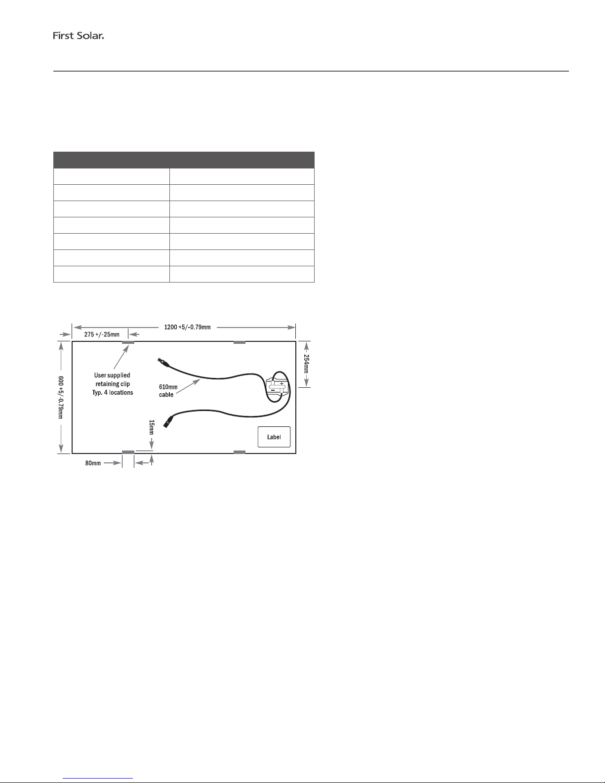
MounngoftheSeries3BlackPlusModuletoasuitablestructurecanbedonebyaachingthemoduledirectlytothe
structureusingretainingclips(seeFigure5.1).
TheretainingclipdesignmustmeetthetechnicalrequirementsspeciedinFirstSolarApplicaonNotePD-5-320andmust
beapprovedforusebyFirstSolarpriortoinstallaon.Themounngsystemdesignmustprovideadequatesupportforthe
moduletopreventdamagefromoccurringwhenthemoduleissubjectedtowindloadsof130km/h,withasafetyfactorof
3forgustycondions.Thelocaonoftheclipsshallbealongthe1200mmlengthofthemoduleandthecenterpointofthe
clipshallbelocatedbetween250mmand300mmfromthemoduleedge.SeeFigure5.1forallowedlocaon.Rubbergasket
material,orequivalentmustbeusedbetweenthemoduleandboththeclipandmounngstructuretoprovideadequate
proteconoftheglasslaminatemodule.Nodirectcontactofrigidstructuresispermiedagainstthesurfaceoredgesofthe
glass laminate.
Allmounngstructuresmustprovideaatplaneforthemodulestobemountedon,andmustnotcauseanytwistorstress
tobeplacedonthemodule.
Modulesshouldnotbeinstalledinawaythatrestrictsaircirculaontotheundersideofthemodule.Modulesgenerateheat
andrequireadequateairowforcooling.
Installaonlocaonsandmodulesupportstructuresshouldbeselectedtoensuremodulesandconnectors(openormated)
areneversubmersedinstandingwater.FirstSolarmodulesaretestedandceredforapplicaonsinvolvingpressures
fromsnow/ice/windupto2400Pawhenmountedproperly.Snowdriscouldresultinanonuniformloadingofthemodules
whichexceedsthetestedpressure.Ifitisexpectedthatloadswillexceed2400Pa,itisrecommendedtoclearsnowfrom
modules,andensurethatice/thaw/freezecyclesundersnowdrisdonotresultinexcessivestressesonthemodule.
Heavyconstruconandtrenchingshouldbecompletedpriortomoduleinstallaontominimizedebrisanddust.
!
!
!
!
Page 7 of 14
Document Number: PD-5-200-03 Plus
Collection: FS Controlled Documents

Series 3 Black Plus Module User Guide—Global | Page 6 of 12
PD-5-200-03 Plus | REV 1.2 | 0281_UG_A4_Plus_9AUG16
Ensureanysoilbindingagentsorsaltsusedforon-sitedustcontroldonotspray,splash,ordriontothesurfaceofthe
modules.
Maximumallowablepressureonmodulesmaynotexceed2400Pawithoutaddionalmodulesupportthatmustbetested
andapprovedbyFirstSolar.
Forrooopmounng,modulesmustbemountedoverareresistantroofcoveringratedfortheapplicaon.The
recommendedminimumstandoheightis8cm.
4.2 Locaon,AngleandTilt
Tomaximizeperformance,modulesshouldbelocatedinanareathatreceivesdirectsunlightfrommid-morningtomid-
aernoon(typically9:00a.m.to3:00p.m.).Installaonmustavoidlocangthemoduleswhereshadowsmaybecausedby
buildings,trees,etc.
PVperformancemodelingsowareshouldbeusedtodeterminetheopmumorientaonandltangleforeachlocaon.
Forltedfree-eldapplicaonswherethereisrowtorowshading,modulesshallbeinstalledinlandscapeorientaon.
PleaserefertoFirstSolarApplicaonNotePD-5-425-03foraddionalinformaon.
4.3 ModuleShadingConsideraons
TominimizetheriskofmoduleshadingdamagepleasefollowtheModuleShadingFieldGuidePD-5-366.Instancesof
shadingthatwillleadtoavoidedwarrantyincludetheHighRisklisteditemsbelow.
High Risk (Prohibited) Shading
1. Resngoradheringslenderobjects(tools,brooms,clothing,wires,tape)onsunnysideofoperangmodules,orwithin
inchesaboveoperangmodules,especiallywhenshadoworientedparalleltocells.
2. Fixedobjectswithin~1.5-2metersaboveoperangmodulesthatcastashadowoverthelongdimensionofthecell
shouldbeavoided.Closeobjectslikeposts,ropes,signs,fences,orequipmentcanbegintoincreaseriskofparal
shadingoffullcellswhennearerthan~1.5-2metersfromthesunny-sideofoperangmodule.
3. Workingconnuouslywithoutstretchedarmsortoolsoveroperangmodules.
4. Asupportframeormounngmethodontheshortedge(s)ofmodulesthatfullyshadestheenrelengthofacell(either
parallyorcompletely).
5. Cleaningapparatuses,includingcleaningrobotsandothermechanismsthattraversethemodulerepeatedlywhilethe
systemisoperang(unlessevaluatedandapprovedbyFirstSolar).
Page 8 of 14
Document Number: PD-5-200-03 Plus
Collection: FS Controlled Documents
Series 3 Black Plus Module User Guide—Global | Page 7 of 12
PD-5-200-03 Plus | REV 1.2 | 0281_UG_A4_Plus_9AUG16
4.4 ElectricalInterconnecon
FirstSolarSeries3BlackPlusModulesarepre-conguredwithindustrystandardconnectorsthatare“touchproof”withall
livepartsprotectedagainstaccidentalcontactandprotectedagainstpolarityreversal.TheconnectorsareUVandweather
resistantfrom–40°Cto+90°C,andratedfor1000VDCand22.5A(minimum,beforederangforambienttemperature).
Damaged wires, connectors, or juncon boxes may cause ground faults, and associated electrical hazards,
including electrical shock. To avoid these condions:
• Protect unmated connectors from dust and moisture by using sealing caps (not provided, available from connector
manufacturer).
• Limit module connectors to 10 or fewer plug cycles.
• Do not pull lead wires ght at any me. Aer installaon, the connected wire must not be under stress or tension.
• Do not use juncon box assembly or lead wire strain relief loops to secure excess wire or to bear weight in excess
of a module’s own wire and mated connector pair.
• Connector bodies and cables should not be ghtly secured at both ends to any mounng structure to allow for
thermal expansion and contracon.
• Secure wire or connected components so that no loose wires or components are hanging within 0.46m (1.5 feet)
of the ground in free eld applicaons, and so that wire/components are hanging clear of roof coverings or pooled
water in rooop applicaons.
• Ensure connectors are fully mated.
• Ensure wire securement methods, such as use of cable es, do not damage wire insulaon. The minimum module
lead wire bend radius is 5 mes wire diameter. Observe minimum bend radius specicaons on all other PV
system wiring.
• Ensure wires are not in contact with sharp edges of the mounng structure to avoid abrading the wire sheath.
• Inspect and maintain wire management requirements over the life of the plant.
Modules with dierent FS Series numbers (i.e. FS 2 vs. FS 3) have signicantly dierent electrical operang
characteriscs and should not be interconnected within the same inverter to prevent power output loss and
voltage imbalance condions that may create the risk of reverse current overload.
FSSeries3,Series3Black,andSeries3BlackPlusModulesareelectricallycompableoneanotherwhenappropriate
systemdesignpraccesareemployed,butmayvaryinmoduleconnectortype.Certaincerfyingbodiesmaynotcerfy
interconneconofthesedierentconnectortypes.Inthesecases,module-moduleandmodule-harnessconneconsmust
eitherbelikeforlikesuppliersoradaptercableconneconswouldbeneeded.
Moduletomoduleandmoduletoharnessinterconneconisadvisedtobedonebetweensamemanufacturerandtype
ofconnectors.TheFirstSolarmodulewarrantyisnotaectedbytheinterconneconofdierentsupplierconnectors,
however,FirstSolarcannotguaranteethatdierentconnectortypeswillbemateableineveryconneconinstance.
!
!
Page 9 of 14
Document Number: PD-5-200-03 Plus
Collection: FS Controlled Documents

Series 3 Black Plus Module User Guide—Global | Page 8 of 12
PD-5-200-03 Plus | REV 1.2 | 0281_UG_A4_Plus_9AUG16
Componentsusedtointerconnectthemodulesmustbecompablewiththeconnectors,andprovidepropersystem
operaonandfaultproteconasrequiredbyanyapplicablecodesandstandards.
WhenconnecngFirstSolarSeries3BlackPlusModulesinaseriesstring,ensurethatthesystemdesignvoltagelimitisnot
exceeded.For1000VDCapplicaons,thisistypicallyensuredbylimingseriesstringsto15modulesorless.
Series3BlackPlusModulesaredesignedforulitygridconnected,commercialandindustrial,o-gridenergyaccess,and
fueldisplacementapplicaons.AllinvertersmustmeetthetechnicalrequirementsspeciedinFirstSolarApplicaonNote
PD-5-310andmustbeapprovedformodulecompabilitybyFirstSolarpriortoinstallaon.Whenconnecngmodulesor
modulestringsinseriesensureinverterrangsareappropriate.
Modulesmustnotbeoperatedundershortcircuitcondionsforextendedduraons.
4.4.1 Grounding Method
FirstSolarSeries3BlackPlusModuleshavenoexposedconducvesurfacesanddonotrequireequipmentgroundingas
longasacliplengthof100mmforastandard4clipmounngisnotexceeded.
FirstSolarSeries3BlackPlusModulescanbeusedinnegave-grounded,ungrounded,oang,andbi-polarsystem
architectures,providedallappropriatedesignrequirementsaremetandapprovedbyFirstSolar.FSSeriesPVModules
shouldnotbeusedinposive-groundedsystems.
4.4.2 Overcurrent Protecon
Series3BlackPlusModuleshaveamaximumovercurrentproteconrangof4.0AasdenedbyIEC61730testmethods.
PVsystemsshouldbedesignedtocomplywithandprovidemoduleovercurrentproteconconsistentwithlocalcodesas
appropriatefortheintendedapplicaonclassofthesystem.
PleaserefertoFSApplicaonNotePD-5-308foraddionalinformaononmoduleovercurrentprotecon.
Page 10 of 14
Document Number: PD-5-200-03 Plus
Collection: FS Controlled Documents
Series 3 Black Plus Module User Guide—Global | Page 9 of 12
PD-5-200-03 Plus | REV 1.2 | 0281_UG_A4_Plus_9AUG16
5 Mechanical Specicaons & Drawings
Table 5.1: Mechanical Specicaons
Specicaons Series 3 Black Plus Modules
Length 1200 mm
Width 600 mm
Thickness 6.8 mm
Area(totalaperture) 0.72 m2
Weight 12 kg
FireRang ClassB(ClassASpreadofFlame)
OperangTemperature -40°Cto+85°C
Figure 5.1 Mechanical Drawing for Series 3 Black Plus Modules
Page 11 of 14
Document Number: PD-5-200-03 Plus
Collection: FS Controlled Documents

Series 3 Black Plus Module User Guide—Global | Page 10 of 12
PD-5-200-03 Plus | REV 1.2 | 0281_UG_A4_Plus_9AUG16
6 Proper Operang Condions
Theproperoperangcondionrequirementslistedbelowmustbemaintained.
Important: Failure to maintain proper operang condion requirements for the modules will void the warranty
(refer to First Solar FS Series Module Warranty Terms & Condions PD-5-102).
Requirements:
• Shortcircuitoperaonispermiedonlyduringshortduraonsystemsafetytesngorinfailsafesystemstates.
• Allelectroniccomponentsthatareinterconnectedtomodulesmusthaveanoperangvoltagewindowthatmatches
themaximumpowerpointofthearray,andbecapableofoperangthearrayatthemaximumpowerpointatall
mes.
• Allelectroniccomponentsthatareinterconnectedtomodulesmustberatedforthemaximumoperangvoltageof
the array.
• Modulesmusthaveadequatevenlaonandairowtopreventoperangtemperaturesabove85°C.
• Modulesmustnotbeparallyshadedbyobstruconsatmesofhighirradiance(typicallybetween9:00amand
3:00pm).Modulerow-to-rowshadinginlandscapeorientaonisacceptable;Modulerow-to-rowshadinginportrait
orientaonisprohibited.
• Modulesmustnotbeusedinposive-groundedorbi-polarsystems.
• Strainreliefcableesmustnotberemoved.
• Ifmodulecleaningisundertaken,modulesmustbecleanedonlywheninopencircuit–eitherdisconnectedfrom
load,orduringmeswheninverteristurnedoandotherwiseinaccordancewithPD-5-804“FSSeriesPVModule
CleaningGuidelines”.
Page 12 of 14
Document Number: PD-5-200-03 Plus
Collection: FS Controlled Documents

Series 3 Black Plus Module User Guide—Global | Page 11 of 12
PD-5-200-03 Plus | REV 1.2 | 0281_UG_A4_Plus_9AUG16
7 Service
• Periodically,annuallyataminimum,inspectmodulesforanysignsofdamageorbrokenglass.
• Brokenmodulesshouldbereplacedimmediately.Ifbrokenmodulesarefound,placematerialintoaclosedcontainer
forreturntoFirstSolarrecyclingprogram,ordisposeofmoduleinaccordancewithlocalrequirements.Pleasevisit
www.rstsolar.com/recyclingforfurtherdetailsontherecyclingprogram.
• Checkthatallelectricalconneconsareghtandcorrosionfree.
• Largeamountsofdustanddirtonthesurfaceofthemodulecanreducethepowerproduced.Naturalrainfallwill
typicallyremovemostdust.Shouldauxiliarycleaningberequired,pleasereferto“FSSeriesPVModuleCleaning
Guidelines”(PD-5-804)foraddionalinformaon.
ThemostcommoncausesoflowerthanexpectedPVsystempoweroutputare:
• Inverter failure
• Improperorfaultyeldwiringorconnecons
• Blownfusesortrippedcircuitbreakers
• Excessive amounts of dirt and dust on the modules
• Shadingofmodulesbytrees,poles,orbuildings
• Improperlycalibratedormalfunconingmonitoringequipment
8 Warranty Terms & Condions
Pleasereferto,“FirstSolarFSSeriesModuleWarrantyTerms&Condions”(PD-5-102)forwarrantyterms,limitaons,and
product return policies.
Page 13 of 14
Document Number: PD-5-200-03 Plus
Collection: FS Controlled Documents

Series 3 Black Plus Module User Guide—Global | Page 12 of 12
PD-5-200-03 Plus | REV 1.2 | 0281_UG_A4_Plus_9AUG16
9 Noce
ChangestocertaincomponentsofthemodulearecommonasFirstSolarconnuouslystrivesforproductimprovements.
Changesmaybearesultofcomponentimprovementsorchangesbyasupplier,orbyminordesignmodicaonsiniated
byFirstSolar.Allproductswithinthesamemodelclassicaonremainfunconallyequivalentandfullycompablewith
oneanother,eventhoughtheremaybeslightdierences.Modicaonsthatdonotimpactthefunconalityoftheproduct
willtypicallybemadewithoutcustomernocaon.Internaltesng,andrevieworretesngbyacerfyingagency,willbe
completedbeforecomponentordesignchangesareintroducedintothemanufacturingprocess.
FirstSolarreservestherighttomakechangesinsolarmoduledesignand/orspecicaonsatanymewithoutnoce.
Accordingly,thereaderiscauonedtoverifythatdatasheetsarecurrentbeforeplacingordersornalizingsystem
permingand/ordesign.InformaonfurnishedbyFirstSolarisbelievedtobeaccurateandreliable.However,no
responsibilityisassumedbyFirstSolaroritssubsidiariesforitsuse;norforanyinfringementsofpatentsorotherrightsof
thirdpareswhichmayresultfromitsuse.Nolicenseisgrantedbyimplicaonorotherwiseunderanypatentorpatent
rightsofFirstSolaroritssubsidiaries.
IntheeventofaconictbetweenthismoduleUserGuideandtheinstruconsofoneofthesystemcomponent
manufacturers,thesystemcomponentinstruconsshouldprevail.
ForinformaonregardingFirstSolaranditsproducts,pleasevisitwww.rstsolar.com.Fortechnicalsupport,pleasecontact
technicalsupport@rstsolar.com.
Global
FirstSolar,Inc.
P.O. Box 730
Toledo,OHUSA43697-0730
Tel: +1(602)414-9300
Fax: +1(602)414-9400
Web: www.rstsolar.com
Email: info@rstsolar.com
Page 14 of 14
Document Number: PD-5-200-03 Plus
Collection: FS Controlled Documents
Table of contents
Other First Solar Solar Panel manuals


Popular Solar Panel manuals by other brands

Waka Waka
Waka Waka SOLAR PANEL manual

Redarc
Redarc SOLAR SMSP1050 manual

Panasonic
Panasonic EverVolt EVPV Series General installation manual

PREFORMED LINE PRODUCTS
PREFORMED LINE PRODUCTS POWER RAIL P14 Assembly instructions

Energeeks
Energeeks EG-CIPBATSOLAR Quick installation guide

SUNRI SOLAR
SUNRI SOLAR SR220-250P SERIES Mounting manual


