First Solar 6 Plus Series User manual
First Solar Series 6 Plus Modules | USER GUIDE
MPD-00594-06
US
REV 2.0
Plus

FIRST SOLAR First Solar Series 6 Plus Modules | USER GUIDE i of 26
FIRST SOLAR, INC. | MPD-00594-06 REV 2.0
Plus
First Solar and the First Solar logo are trademarks of First Solar, Inc., registered in the U.S. and other
countries. Series 6 Plus is a trademark of First Solar, Inc.
NOTICE
First Solar reserves the right to make changes in solar module design and/or specifications at any time
without notice. Accordingly, the reader is cautioned to verify that data sheets are current before placing
orders or finalizing system permitting and/or design. Information furnished by First Solar is believed to be
accurate and reliable. However, no responsibility is assumed by First Solar or its subsidiaries for its use; nor
for any infringements of patents or other rights of third parties, which may result from its use. No license is
granted by implication or otherwise under any patent or patent rights of First Solar or its subsidiaries.
CONTACT INFORMATION
For information regarding First Solar and its products, please visit www.firstsolar.com. First Solar has an
extensive library of supporting Application Notes that can be made available upon request from technical
support technicalsupport@firstsolar.com.
First Solar, Inc.
P.O. Box 730
Toledo, OH USA 43697-0730
Tel: +1 (602) 414-9300
Fax: +1 (602) 414-9400

FIRST SOLAR First Solar Series 6 Plus Modules | USER GUIDE ii of 26
FIRST SOLAR, INC. | MPD-00594-06 REV 2.0
Plus
TABLE OF CONTENTS
1INTRODUCTION 1
2SAFETY 2
3REGULATORY COMPLIANCE 4
4PRODUCT IDENTIFICATION & RATINGS 5
4.1 PRODUCT IDENTIFICATION & RATINGS 5
4.2 WIRING SYSTEM DERATING FACTORS 6
5HANDLING & STORAGE 7
5.1 HANDLING & STORAGE 7
5.2 PRODUCT DIFFERENTIATION 8
6MECHANICAL SPECIFICATIONS 9
7INSTALLATION & MOUNTING 10
7.1 MOUNTING 10
7.2 MOUNTING LOCATIONS & LOAD RATINGS 11
7.3 TOP MOUNTING 14
7.4 SPEEDSLOT MOUNTING 15
7.5 MODULE ORIENTATION 16
7.6 MODULE SHADING CONSIDERATIONS 16
7.7 WIRE MANAGEMENT 17
7.8 ELECTRICAL INTERCONNECTION 19
7.9 INVERTER COMPATIBILITY 20
7.10 GROUNDING METHOD 21
8MAINTENANCE 23
8.1 MAINTENANCE 23
8.2 MODULE CLEANING GUIDANCE 24
8.3 MODULE DISPOSAL 25
9REVISION HISTORY 26

FIRST SOLAR First Solar Series 6 Plus Modules | USER GUIDE 1 of 26
1INTRODUCTION
This document provides information on First Solar Series 6 Plus modules (including both Series 6 Plus SL
and Series 6 Plus HL) for system designers, installers, and maintenance personnel. In instances that do not
apply to both the Series 6 Plus SL and Series 6 Plus HL, the User Guide will specifically name and detail
both product types as necessary.
The Series 6 Plus model types follow the below formats where “XXX” references the module power rating
and “A” indicates model types with an anti-reflective coating (ARC) on the front side surface.
•Series 6 Plus SL: FS-6XXX-P-I and FS-6XXXA-P-I
•Series 6 Plus HL: FS-6XXX-P and FS-6XXXA-P
Series 6 Plus modules are designed to have a long operating life and high energy yield when installed,
operated, and serviced in accordance with the instructions in this User Guide. Read this User Guide
thoroughly before beginning any work related to installation, operation, or maintenance of the First Solar
Series 6 Plus module.
Please refer to your First Solar Module Warranty Terms & Conditions for module warranty terms and product
return policies. Failure to follow this User Guide may void your warranty.
Keep this User Guide for future reference and provide to all subsequent owners or users of the
solar modules. Updates may be found at www.firstsolar.com.

FIRST SOLAR First Solar Series 6 Plus Modules | USER GUIDE 2 of 26
FIRST SOLAR, INC. | MPD-00594-06 REV 2.0
Plus
2SAFETY
All instructions and safety information should be read and understood before attempting to handle, install,
or electrically connect First Solar modules. Failure to follow safety, installation, and handling instructions
may result in injury. Only qualified personnel should install, operate, or maintain PV modules or systems.
Series 6 Plus modules are designed for 1000 V systems at altitudes up to 5000 m (16404 ft) per IEC
61730 and UL 61730. Series 6 Plus modules are designed for 1500 VDC systems at altitudes up to 3000
m (9842 ft) per IEC 61730 and UL 61730.
Select installation locations and module support structures to ensure modules and connectors (open or
mated) are never submerged in standing water.
DANGER
Series 6 Plus modules may produce up to 280 Volts DC (VDC) and up to 4.0 A when exposed to
sunlight. The danger increases as modules are connected together in series and/or parallel.
A single module or multiple interconnected modules can create a lethal shock hazard during
daylight hours, including periods of low light levels
.
DANGER
To avoid fire and/or injury
due to ground faults and associated electrical hazards:
►Do not unplug PV module connections while under load. Do not disconnect the module
connectors during daylight hours unless the module is in an open circuit condition.
►Replace modules with damaged wires immediately. Keep all array wiring out of reach of
non-qualified personnel.
►Do not concentrate light on the module in an attempt to increase power output.
►Never allow the PV array system voltage to exceed 1500 VDC under any condition.
►Replace broken modules immediately.
►Repair ground faults immediately.
►Do not work on modules or systems when the modules or wiring is wet.
►All building mounted PV systems should utilize Ground Fault Detector Interrupters (GFDI)
and ARC Fault Circuit Interrupters to minimize risk of electrical shocks and fires.
Series 6 Plus modules have a maximum overcurrent protection rating of 5.0 A as defined by IEC/UL 61730-
1 and IEC/UL 61730-2. PV systems should be designed to comply with and provide module overcurrent
protection consistent with local codes.
FIRST SOLAR First Solar Series 6 Plus Modules | USER GUIDE 3 of 26
FIRST SOLAR, INC. | MPD-00594-06 REV 2.0
Plus
The conditions necessary to trigger reverse current overload (RCOL) do not occur in typical operating modes
of a properly installed PV system. The system designer should ensure that modules are not subjected to
RCOL. The use of GFDI devices or other advanced fault monitoring techniques can significantly reduce the
likelihood of sustained ground faults. Properly selected and installed string fuses can increase protection
against RCOL.
DANGER
Reverse currents
higher than the rated values for a First Solar module, may result in module
failure, including module breakage due to RCOL. Extreme and continuous RCOL conditions may
cause a fire or create electrical shock hazards. To avoid RCOL:
►Maintain equivalent voltage in parallel strings by installing an equal number of modules
per string within the same source circuit. Failure to install modules with balanced voltage
in parallel strings can result in voltage imbalance.
►Incorporate measures to protect modules against RCOL for connections of parallel strings.
Modules damaged because of system-induced RCOL are not covered under the First Solar Module
Warranty. Module warranty eligibility is not affected by the presence, absence, or type of reverse current
protection used in a system design.
CAUTION
Wear safety glasses
and
cut-resistant gloves
when working with non-interconnected modules or
system components.
Wear electrically rated PPE
when working with interconnected modules or system components.
Select PPE based on work consistent with local and/or national standards.
WARNING
To avoid risk of fire, do NOT interconnect Series 6
Plus
modules with other FS Series modules
(e.g. – Series 4, Series 3, or Series 2) within the same interconnected string, inverter, or
Maximum Power Point Tracker.

FIRST SOLAR First Solar Series 6 Plus Modules | USER GUIDE 4 of 26
FIRST SOLAR, INC. | MPD-00594-06 REV 2.0
Plus
3REGULATORY COMPLIANCE
It is the responsibility of the installer and/or system integrator to ensure compliance with all local structural
and electrical codes, which may be applicable to the installation and use of First Solar Series 6 Plus
modules.
For systems installed in North America, First Solar Series 6 Plus modules are Listed by a Nationally
Recognized Test Laboratory (NRTL) to UL 61730, the standard for Flat-Plate Photovoltaic Modules and
Panels. To maintain the modules’ application as a UL Listed product:
►Use only components that have been Recognized or Listed by Underwriters Laboratories (UL) for
their intended purpose.
►Ensure the PV array open-circuit voltage does not exceed 1500 VDC.
►Install modules with mounting systems that have been evaluated for UL Listed application.
►Protect modules from reverse currents in excess of the 5.0 A maximum series fuse rating.
►The module is considered to be in compliance with the applicable UL standard only when the
module is mounted in the manner specified by the mounting instructions in this User Guide.
►A module with exposed conductive parts is considered to be in compliance with the applicable UL
standard only when it is electrically grounded in accordance with this User Guide and the
requirements of the National Electrical Code, ANSI/NFPA 70.
Series 6 Plus modules are tested and certified per IEC 61730-1/IEC 61730-2 and meet Class II
requirements for 1500 VDC systems.
Series 6 Plus modules are tested and certified per IEC 61215-1/IEC 61215-1-2/IEC 61215-2 for a
maximum system voltage of 1500 VDC.
FIRST SOLAR First Solar Series 6 Plus Modules | USER GUIDE 5 of 26
FIRST SOLAR, INC. | MPD-00594-06 REV 2.0
Plus
4PRODUCT IDENTIFICATION & RATINGS
4.1 PRODUCT IDENTIFICATION & RATINGS
Each module is equipped with a product label on the back and laser-etched identification on the front glass.
The label identifies the model number, nameplate electrical ratings, and safety information.
The module Rated Power is denoted in the ‘XXX’ position of the base Model Number format of FS-6XXX-P.
(Example: FS-6460A-P has a Rated Power of 460W)
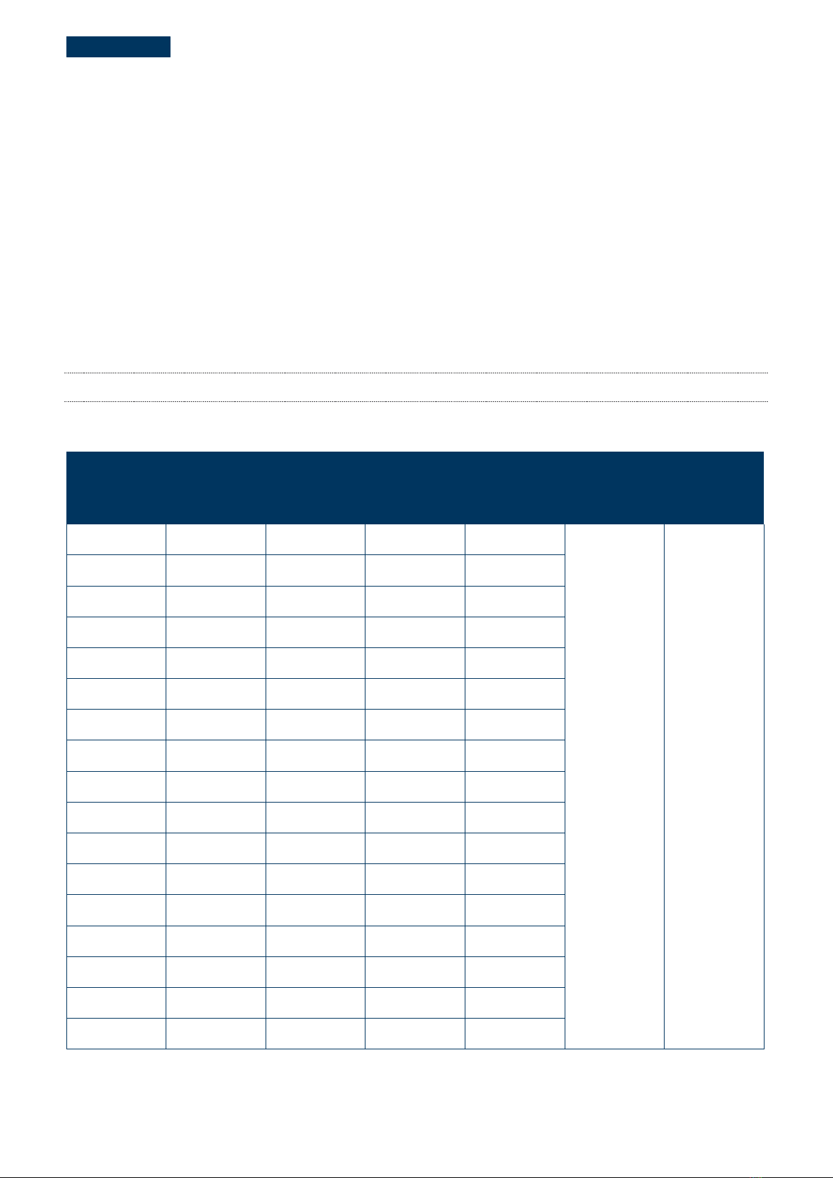
The ratings in Table 1 are UL Listed with a tolerance of ±10% unless otherwise noted.
Note: Electrical specifications are subject to change. See label for final electrical ratings.
Table 1: Model Numbers & Ratings at Standard Test Conditions (STC1)
RATED POWER2
(-0/+5%)
VOLTAGE AT
PMAX
CURRENT AT
PMAX
OPEN CIRCUIT
VOLTAGE
SHORT CIRCUIT
CURRENT
MAX SYSTEM
VOLTAGE
MAX SERIES
FUSE
P
MAX
(W)
V
MAX
(V)
IMAX(A)
VOC(V)
ISC(A)
V
SYS
(V)
ICF(A)
390.0 173.9 2.24 214.8 2.49
1500 5.0
395.0 175.0 2.26 215.4 2.50
400.0 176.1 2.27 216.1 2.51
405.0 177.2 2.29 216.8 2.52
410.0 178.3 2.30 217.4 2.52
415.0 179.3 2.31 218.1 2.53
420.0 180.4 2.33 218.5 2.54
425.0 181.5 2.34 218.9 2.54
430.0 182.6 2.36 219.2 2.54
435.0 183.6 2.37 219.6 2.55
440.0 184.7 2.38 220.0 2.55
445.0 185.7 2.40 220.4 2.56
450.0 186.8 2.41 221.2 2.57
455.0 187.7 2.42 222.0 2.58
460.0 188.8 2.44 222.9 2.59
465.0 189.8 2.45 223.8 2.60
470.0 191.1 2.46 224.3 2.61
1As received and stabilized ratings at STC (1000 W/m², AM1.5, (25 ± 2)°C Cell Temperature) ±10%
2Measurement uncertainty applies

FIRST SOLAR First Solar Series 6 Plus Modules | USER GUIDE 6 of 26
FIRST SOLAR, INC. | MPD-00594-06 REV 2.0
Plus
Table 2: Temperature Characteristics
TEMPERATURE CHARACTERISTICS
Module Operating Temperature Range (°C) -40 to +85
Temperature Coefficient of PMAX
T
k
(P
MAX
)
-0.32%/°C (Temperature Range: 25°C to 75°C)
Temperature Coefficient of VOC
T
k
(V
OC
)
-0.28%/°C
Temperature Coefficient of ISC
T
k
(I
SC
)
+0.04%/°C
4.2 WIRING SYSTEM DERATING FACTORS
Under normal operation, a PV module may experience conditions that produce higher current and/or
voltage than reported at STC. Accordingly, the values of Isc and Voc listed for STC should be multiplied by a
factor of 1.25 when determining component voltage ratings, conductor current ratings, and size of controls
connected to the PV output. For UL installations, an additional 1.25 safety factor for short circuit current
may be applicable, reference the National Electric Code (NEC) Article 690 for further details. Specific site
conditions and local electric code requirements must be used for determining the maximum system
voltage.
When calculating module Voc at 125 mW/cm2, AM1.5 spectrum, and cell temperature of -10°C,
multiply the specific model type STC listed Voc value by a factor of 1.1. When calculating module Isc
at 125 mW/cm2, AM1.5 spectrum, and cell temperature of 75°C, multiply the specific model type STC
listed Isc value by a factor of 1.27.
As per NEC 690 (A) an acceptable method of calculating Voc is published by Sandia National Laboratories
(reference SAND 2004-3535, Photovoltaic Array Performance Model). This model uses irradiance and
temperature of a given location to forecast expected open circuit Voltages on a project specific basis.
FIRST SOLAR First Solar Series 6 Plus Modules | USER GUIDE 7 of 26
FIRST SOLAR, INC. | MPD-00594-06 REV 2.0
Plus
5HANDLING & STORAGE
5.1 HANDLING & STORAGE
When handling packs using forklifts or other mechanical aids, ensure uniform pack support, and the forks
fully extend under the pallet. Packs can be lifted from either the short or long side of the pallet. Forklifts
must engage the pallet a minimum of 1.3 m (51 in) for long side engagement and a minimum of 1.5 m (60
in) for short side engagement. Failure to meet engagement lengths may damage pallet and modules on
bottom of pack.
Modules on a pack may lean or shift on a pallet during shipping. It is recommended to unload shifted packs
one at a time. Do not unload or lift stacked packs from the short side. If any damage is observed, use the
Delivery Note to document affected pallets and contact technicalsupport@firstsolar.com.
Only originally banded, fully intact and loaded packs may be stacked for storage up to two high for three
weeks on site or extended periods in a warehouse. Packs should not be stacked if rebanded on site, if any
corner braces or top cap material has been removed, or if any banding is broken from the pack.
►Do not transport stacked packs around project site.
►Do not attempt to transport the pack once the straps have been removed.
Please evaluate site conditions for safe pack storage as uneven or recently disturbed ground and moisture
may affect pack stability. Packs are not intended for long-term outdoor storage. Packs should not be
exposed to standing water higher than half the height of the pallet.
WARNING
Open the packaging with care. A single person should not attempt to lift a Series 6 Plus module
.
Lift the modules from the pallet with two or more persons or with lift assist.
Do not attempt to lift
multiple modules off the stack at the same time.
During handling and installation, do not make abrasive contact with top glass surface to prevent
scratches of ARC film.
The pack’s cap includes two green markings for module orientation purposes. The long edge green
orientation mark corresponds to the side of the module with the positive junction box cable.
FIRST SOLAR First Solar Series 6 Plus Modules | USER GUIDE 8 of 26
FIRST SOLAR, INC. | MPD-00594-06 REV 2.0
Plus
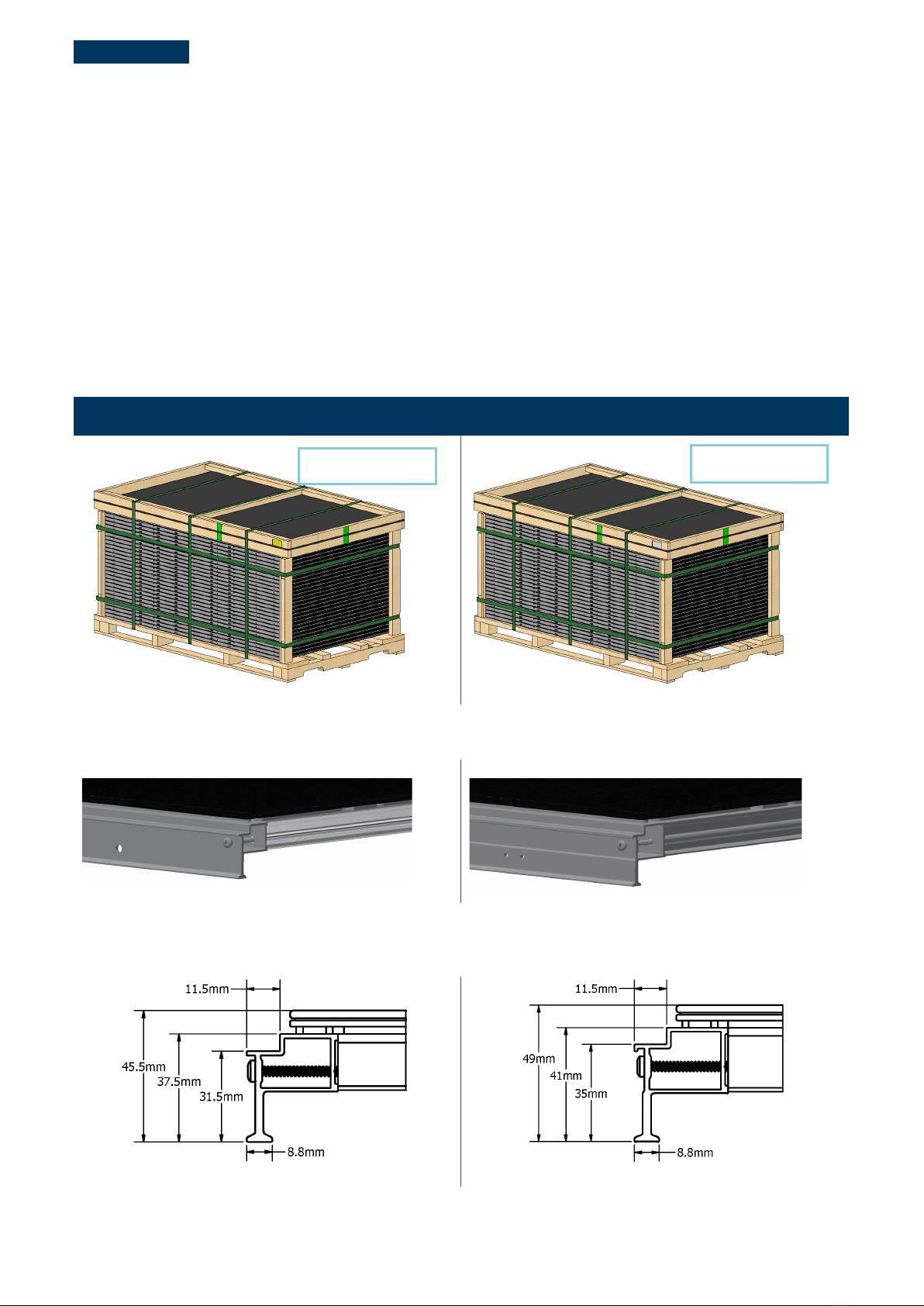
5.2 PRODUCT DIFFERENTIATION
Series 6 Plus SL and Series 6 Plus HL product packaging and labeling are differentiated by the following:
►Number of modules per pack
oSeries 6 Plus SL= 30 per pack
oSeries 6 Plus HL = 27 per pack
►Model number presence on the module product label and pack label
►Color of the module product label and pack label (Figure 1)
►Quantity of holes at each end of the long frame side (Figure 2)
Series 6
Plus SL
FS-6XXX-P-I / FS-6XXXA-P-I
Series 6
Plus HL
FS-6XXX-P / FS-6XXXA-P
Figure 1:
Pack Label Color Differentiation
Figure 2:
Differentiation Holes on Long Edge Frame Isometric View
Figure 3: Long Edge Frame Detail
White Pack Labels
Yellow Pack Labels
Two Holes
One Hole

FIRST SOLAR First Solar Series 6 Plus Modules | USER GUIDE 9 of 26
FIRST SOLAR, INC. | MPD-00594-06 REV 2.0
Plus
6MECHANICAL SPECIFICATIONS
Table 3: Series 6 Plus Module Mechanical Specifications
SPECIFICATION
Series 6
Plus SL
Series 6
Plus HL
Module Weight 33.3 kg +1.5/-2.5 kg (73.4 lbs +3.3/-5.5 lbs) 34.0 kg +1.5/-2.5 kg (75 lbs +3.3/-5.5 lbs)
Top Mount Frame Height 31.5 mm ± 1 mm (1.24 in ± 0.04 in) 35 mm ± 1 mm (1.38 in ± 0.04 in)
Length 2024 mm +3/-1 mm (79.7 in +0.11/-0.04 in)
Width 1245 mm ± 2 mm (49.0 in ± 0.08 in)
Total Area 2.52 m² (27.1 ft²)
Junction Box Lead Wire32.5 mm² (14 AWG)
733 mm (28.86 in) (+) & Bulkhead (-)
Fire Performance3Type 19: Class A Spread of Flame / Class C Burning Brand
Figure 4:Series 6 Plus Module Mechanical Drawing
3Length from junction box exit to connector mating surface
3Module UL 61730 fire rating is valid only when mounted in the manner specified in this User Guide. Roof mounted fire rating is
established by assessing rack and module as a unit. External fire source resistance has not been evaluated.
FIRST SOLAR First Solar Series 6 Plus Modules | USER GUIDE 10 of 26
FIRST SOLAR, INC. | MPD-00594-06 REV 2.0
Plus
7INSTALLATION & MOUNTING
7.1 MOUNTING
It is best practice to complete heavy construction and trenching prior to module installation to minimize
module exposure to dust. Ensure any site preparation or maintenance chemicals (soil binding agents or
chemicals used for on-site dust control or weed control) do not spray, splash, or drift onto the surface of the
modules or its associated components.
It is the responsibility of the qualified engineer and/or qualified installer to ensure the system and its
components meet applicable structural and electrical code requirements for the product application’s
jurisdiction. First Solar is not responsible for bonding failure, breakage, damage, wear, corrosion, or module
performance issues that are deemed to be caused by design or installation practices that do not comply
with this User Guide.
CAUTION
Safety hazards or potentially unsafe practices:
►Do not install the modules during high wind or wet conditions.
►Handle modules with care during installation, as heavy impact to the front, back, or
edges could result in damage to the module. Do not impact module with hammer to
aid installation process.
►Do not walk, stand, or sit on modules.
►Do not carry multiple modules on top of one another after removal from pack.
►Do not lift or pull on modules using lead wire or junction boxes.
►Do not rest objects (such as tools, etc.) on module glass.
Modules must have adequate ventilation and airflow to prevent operating temperatures above 85°C.
For rooftop mounting, mount modules over a fire resistant roof covering rated for the application. The
recommended minimum standoff height is 8 cm (3.15 in). Series 6 Plus modules may be installed at an
installation angle up to 60°.
For applications where module is mounted above water (i.e. Floating PV):
►Modules may be deployed over inland freshwater, with a minimum clearance of 6 inches (15cm)
above maximum design wave height for any part of module, including module lead wire and
connector.
►Mounting over saltwater or brackish water is prohibited.
Mounting structure must ensure module remains in a fixed position and isolated from wave-induced torsion
and stress.

FIRST SOLAR First Solar Series 6 Plus Modules | USER GUIDE 11 of 26
FIRST SOLAR, INC. | MPD-00594-06 REV 2.0
Plus
7.2 MOUNTING LOCATIONS & LOAD RATINGS
The interface of the mounting structure to the module frame must meet the technical requirements
specified in this User Guide. The mounting system design must provide adequate support for the module to
prevent load damage from occurring based on the loading requirements for the given application and the
chosen mounting locations. Structures must not come into direct contact with the surface or edges of the
module glass or center cross brace(s).
Modules can be secured to the support structure with top (front side) mounting clamps or by frame slots,
known as SpeedSlotsTM.
Series 6 Plus modules have been evaluated to operate in an ambient air temperature range of at least -40°C
to +40°C and have been tested to wind/snow loads as detailed in Table 4. Test loads include a safety factor
of 1.5 above the design loads.
Series 6 Plus modules meet the following load ratings when mounted as specified in this User Guide and
evaluated according to the listed standard in Table 4.
Table 4: Series 6 Plus Module Load Ratings
Product
Mount
Config.
Symmetrical
Four-point
Mount
Location
IEC 61215 / IEC 61730
UL 61730
Design Load
Test Load
Design Load
Test Load
Series 6
Plus
SL
A4
Top Mount:
1200 mm (C/C)
SpeedSlot
Mount:
1200 mm
± 1600 Pa
(± 33.4 lb/ft2)
± 2400 Pa
(± 50.1 lb/ft2)
± 1600 Pa
(± 33.4 lb/ft2)
± 2400 Pa
(± 50.1 lb/ft2)
B
Top Mount:
Range of
400mm to
1000 mm (C/C)
SpeedSlot
Mount:
400 mm
800 mm
+1300 / -900 Pa
(+27.2 / -18.8 lb/ft2)
+1950 / -1350 Pa
(+40.7 / -28.2 lb/ft2)
Series 6
Plus
HL
C
Top Mount:
Range of
400mm to
1200 mm (C/C)
SpeedSlot
Mount:
400 mm
800 mm
1200 mm
± 1600 Pa
(± 33.4 lb/ft2)
± 2400 Pa
(± 50.1 lb/ft2)
± 1600 Pa
(± 33.4 lb/ft2)
± 2400 Pa
(± 50.1 lb/ft2)
4Series 6 Plus SL product is IEC 61215/IEC 61730 certified at Mounting Configuration A only when supplemented with additional
interface point(s). Consult First Solar for supplemental documentation.

FIRST SOLAR First Solar Series 6 Plus Modules | USER GUIDE 12 of 26
FIRST SOLAR, INC. | MPD-00594-06 REV 2.0
Plus
Symmetrically secure the module using a minimum of four frame contact points regardless if mounted with
top clamps or with SpeedSlot clamps. Other mounting solutions not discussed in this User Guide (Such as -
asymmetric mounting, higher load ratings, alternative clamp geometry, etc.) may be permitted, but require
evaluation by First Solar (technicalsupport@firstsolar.com). First Solar reserves the right to reasonable
access to validate proper installation.
►The modules shall have a minimum spacing gap of 6 mm (0.24 in) between each other. Usable
junction box lead wire lengths accommodate spacing up to 245 mm (9.65 in) (assuming no
substructure interference).
►Do not use module short edge frame sides or center cross braces for mounting unless specifically
evaluated and approved by First Solar in writing.
►Do not modify the module frame in any way. This includes drilling additional holes, altering mounting
features (slots), or otherwise cutting, trimming, or shaping any part of the module frame.
►Module mounting structure support under clamps must maintain a minimum bearing area length of
35 mm (1.38 in) and maintain full frame bottom flange engagement under load.
►Module attachment hardware (i.e. clamps, bolts, etc.) must not contact the module glass.
►Install clamps to the torque stated by the mounting hardware manufacturer.
►Mounting clamps certified/designed to electrically bond and/or ground the module frame are
allowed when used in accordance with the clamp manufacturer’s instructions.
►The maximum clamp force shall not exceed 5500 N for either top or SpeedSlot clamps.
►Minor clamp deformation under load may be acceptable as long as clamping force is maintained
and the deformation does not contribute to a weakening of the clamp or dislodgement of the
module.
Series 6 Plus SL modules are optimized for lower wind speed applications and meet a reduced mechanical
design load per UL 61730, depicted in Table 4. Engineered utility-scale systems utilizing zoned pressure
analysis and certain eligible mounting structure types may benefit from utilizing Series 6 Plus SL modules.
•The Structural Engineer of Record shall calculate the project-specific zoned site pressures to
determine the eligible quantities of both Series 6 Plus SL and HL modules for each project and
document the eligible quantities clearly on the final approved construction drawings for the project.
•In turn, it is the responsibility of the module purchaser to communicate these documented eligible
quantities of Series 6 Plus SL and HL modules for each project in sufficient advance notice as
defined in the module sale agreement to First Solar (contractmanagement@firstsolar.com) to
ensure appropriate module allocation and to remain compliant with module purchase order
requirements.
While many projects will incorporate a single module type, some projects may benefit from utilizing a mix of
both Series 6 Plus HL and SL module types. For these mixed zone cases, it is recommended all array
positions be designed to mechanically accommodate the Series 6 Plus HL product. Accommodating the
heavier Series 6 Plus HL module in the project design allows it to be used in all array locations as a
universal substitute in event Series 6 Plus SL modules are unavailable, and also enables the Series 6 Plus
HL as a universal replacement if needed in the future. To enable this universal Series 6 HL compatibility,
the Structural Engineer of Record shall use the following guidance:

FIRST SOLAR First Solar Series 6 Plus Modules | USER GUIDE 13 of 26
FIRST SOLAR, INC. | MPD-00594-06 REV 2.0
Plus
•Design the Series 6 Plus module mounting interfaces to utilize the SpeedSlot feature, given the
universally consistent interface dimensions for both Series 6 Plus SL and HL module types. This
avoids the potential risk in managing the different rail top clamp height dimensions between Series
6 Plus SL and HL products.
Utilize the weight specification of the Series 6 Plus HL product from Table 3 for structural racking design,
top-of-pile calculations, and post design calculations for all array positions.
CAUTION
Series 6 Plus SL product may only be deployed in engineered PV systems, where the
following conditions are met:
►UL 61730 is the applicable certification standard (in any instance where a
module mounting method results in a <1600 Pa load capability per Table 4 or
otherwise documented by First Solar).
►When PV modules are intended to be installed in an engineered scenario by
qualified personnel such as in a ground-mounted PV power generation plant,
they may be designed to meet a lower minimum test load of 1200 Pa with a
safety factor of 1,5: i.e. an 800 Pa minimum design load for the down
pressures (positive) and uplift pressures (negative). These modules are marked
by “Reduced mechanical design load” on the nameplate followed by the range
of positive and negative design loads they are designed for. As an example,
these modules may be used in interior or exterior rows where the module
mounting and structure in combination are designed to meet a specific design
load lower than 1600 Pa and a licensed professional engineer has taken into
consideration all factors below for the combined site specific wind and snow
loads.
oPressure coefficients should be derived based on an effective wind area
equal to one PV module, from boundary layer wind tunnel tests or
equivalent on the specific mounting system used to support the PV module.
oBoundary layer wind tunnel tests should be conducted in accordance with
ASCE 7 and ASCE 49, or other recognized industry guidance;
oMounting system vibrations with natural frequencies less than 10 Hz may
result in loads higher than predicted from static load calculations,
depending on wind speed and damping ratio of the vibration mode, and
should be considered to assess dynamic amplification factors;
oSome mounting systems may be susceptible to instabilities due to vortex
shedding which may not be addressed in building codes; guidance from
qualified experts in boundary layer wind tunnel testing of ground-mounted
PV systems may be required to address this risk;
oModules when mounted on trackers that rely on being operational or
stowing at a specified angle in extreme wind or snow conditions should be
verified to limit loads below the design load threshold considering the
design controls implemented in such trackers.
►Alternatively, Series 6 Plus HL modules having a higher minimum design load
compatible to the required site-specific loads may be used. Series 6 Plus SL
cannot be used on a rooftop system.

FIRST SOLAR First Solar Series 6 Plus Modules | USER GUIDE 14 of 26
FIRST SOLAR, INC. | MPD-00594-06 REV 2.0
Plus
7.3 TOP MOUNTING
Center each clamp +/- 12 mm (0.48 in) within mounting range or location (detailed in Table 4) to meet
documented load ratings based on model type. Top mounting clamps must have a uniform frame
engagement area of 9 mm (0.35 in) minimum width on the top ledge and 30 mm (1.18 in) minimum length
as depicted in Figure 5. Module clamps may not continuously span the top of the frame across the midpoint
of the long edge frame (to allow for module deflection). Clamps that do not meet the minimum
requirements may not preserve module certifications or warranty and must be evaluated by First Solar
(technicalsupport@firstsolar.com).
Figure 5: Shared Top Clamp Detail

FIRST SOLAR First Solar Series 6 Plus Modules | USER GUIDE 15 of 26
FIRST SOLAR, INC. | MPD-00594-06 REV 2.0
Plus
7.4 SPEEDSLOT MOUNTING
The Series 6 Plus module frames include six SpeedSlots on each side. SpeedSlot clamps must either
extend 10 mm (0.39 in) beyond the inner edge of the frame, or have a retention feature to prevent module
frame dislodgement under load. SpeedSlot clamps must be at least 12 mm (0.47 in) wide from attachment
point through the 10 mm (0.39 in) extension or until point of retention feature, shown in Figure 8. Clamps
should rest on the flat surface of the SpeedSlot.
Figure 6: SpeedSlot Dimensions
Figure 7:
SpeedSlot Detail on Long Edge Frame
Figure 8: Shared SpeedSlot Clamp Detail
FIRST SOLAR First Solar Series 6 Plus Modules | USER GUIDE 16 of 26
FIRST SOLAR, INC. | MPD-00594-06 REV 2.0
Plus
7.5 MODULE ORIENTATION
PV performance modeling software, such as PlantPredict (http://www.plantpredict.com), should be used to
determine the optimum orientation and tilt angle for each location.
Mount modules in portrait orientation for applications where row-to-row shading could occur. Landscape
orientation is permitted only in flat mount applications where the module long edge is not completely
shaded and when compliant with Section 7.6 Module Shading Considerations.
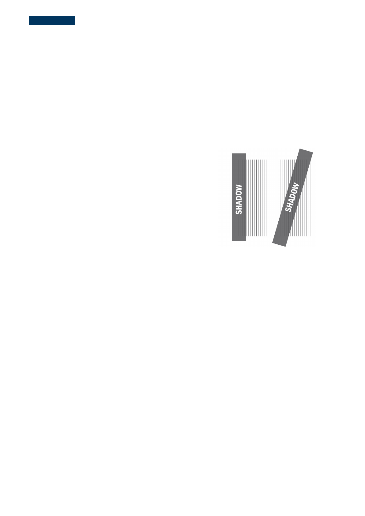
7.6 MODULE SHADING CONSIDERATIONS
Specific shading patterns can cause damage to module cells
due to the creation of localized areas of reverse bias. Reverse
bias is generated by one or more series-connected cells being
shaded while the rest of the cells are fully illuminated. When
at-risk shading patterns occur, damage can occur in short
durations (seconds to minutes) and a wide range of irradiance
(as low as 160 W/m²).
There is no risk of module damage due to shading that occurs
while modules are in open circuit. Shading that occurs at a
distance greater than 2 m (6.6 ft), also known as diffuse
shading, carries reduced risk and should be avoided where
possible. Row-to-row shading of modules installed in portrait
orientation is acceptable.
There is a low risk of module damage due to shading from repeatedly walking or standing in front of
operating modules or from repeatedly parking or driving vehicles in front of operating modules during
illuminated times. It is best practice to stay close to the backside of the adjacent rack as one travels down a
row of operating modules.
Do not subject modules to high risk shading instances listed below:
►Resting or adhering slender objects (tools, brooms, clothing, wires, tape) on front-side of operating
modules, or when within ~2 m (~6.6 ft) above operating modules, especially when the shadow is
oriented parallel to cells
►Fixed objects within ~2 m (~6.6 ft) above operating modules that cast a shadow over the long
dimension of the cells. Close objects (posts, ropes, fences, etc.) can begin to increase risk of partial
shading of full cells when within ~2 m (~6.6 ft) from the front-side of operating module
►A support frame or mounting method on the long edge(s) of modules that fully shades the entire
length of a cell (either partially or completely)
►Cleaning robots or other mechanisms that traverse the module while the system is operating
►Row-to-row shading when the modules are installed in landscape orientation
►Closely “stair-stepped” trackers on northerly slopes (northern hemisphere), or southerly slopes
(southern hemisphere).
Figure 9: Example of at-risk shading
patterns

FIRST SOLAR First Solar Series 6 Plus Modules | USER GUIDE 17 of 26
FIRST SOLAR, INC. | MPD-00594-06 REV 2.0
Plus
7.7 WIRE MANAGEMENT
All wire management shall comply with the applicable NEC/IEC codes and standards for maintaining and
managing wires, as well as any applicable local requirements determined by local authorities having
jurisdiction. This document includes evaluation of general wire management requirements based on
interpretation of the following codes and standards and does not substitute for a comprehensive evaluation
of applicable requirements:
►NEC 2017
o300.3(C)(2) – Conductors of Different Systems
o334.30 – Support and Securement Spacing
o338.24 – Cable Bend Radius Requirements for Type USE cable
►IEC
o62548:2016, 7.3.7.3 – Erection Method
o62548:2016, 7.3.8 – Segregation of AC and DC Circuits
o60364-5-52:2009, 522.8.3 – Cable Bend Radius
Below is a list of best practices that applies to the majority of wire management scenarios:
►The connectors, X/T joints, and in-line fuses should not be in direct contact with the metal frame or
structure. It is recommended that insulated cables do not come in direct contact with the metal
frame or structure, unless unavoidable, to minimize stresses on components.
►The installation of harnesses, harness jumpers, harness whips, and PV array cables (or “Homerun”
cables) should not subject the connectors, X/T joints, and in-line fuses to tensile loads.
►Cable ties should be a minimum distance of 25 mm (1 in) from connectors, X/T joints, and in-line
fuses.
►Cables should not maintain constant contact with the edges of glass-to-glass solar module
laminates.
►Cable ties should be tensioned such that there is at least 13 mm (0.5 in) (two-finger-gap) between
the top of the cable bundle and the bottom of the frame.
Figure 10:Grounding Hole & Wire Management Hole Detail from Frame Center5
5Quantity of differentiation holes vary between Series 6 Plus SL and Series 6 Plus HL. See Figure 2.
DIFFERENTIATION HOLES
This manual suits for next models
2
Table of contents
Other First Solar Solar Panel manuals


Popular Solar Panel manuals by other brands

Sharp
Sharp NA-E115L5 installation manual

Maxeon
Maxeon SunPower SPR-MAX5-415-E3-AC Safety and installation instructions

Hyundai
Hyundai HiS-MxxxMF installation manual

Viessmann
Viessmann VITOSOL 200 installation instructions

sunsei
sunsei SolarCharger 4000 operating instructions

Schweizer
Schweizer Solrif XL installation manual

TALESUN
TALESUN TP672M-330 installation manual

Meyer Burger
Meyer Burger WHITE Installation and operating manual

FulTyme RV
FulTyme RV 3098 instruction manual

Van Der Valk
Van Der Valk ValkPro+ L10 East-West installation manual

TOLEDO SOLAR
TOLEDO SOLAR TS2-WS user guide

Sunforce
Sunforce 85 WATT MONOCRYSTALLINE SOLAR PANEL user manual


