Firstech, LLC. FT-DC2-S User manual

REVISION DATE
20161025
DOCUMENT NUMBER
NOTICE
The manufacturer will accept no responsability for any electrical damage resulting from
improper installation of this product, be that either damage to the vehicle itself or to the
installed device. This device must be installed by a certified technician. Please review the
Installation Guide carefully before beginning any work.
U.S. Patent No. 8,856,780
PRODUCT GUIDE
FT-DC2-S
www.idatalink.comAutomotive Data Solutions Inc. © 2016

U.S. Patent No. 8,856,780
GETTING STARTED
WELCOME
NEED HELP?
Congratulations on the purchase of your FT-DC2
solution. You are now a few simple steps away
from enjoying your new remote starter unit with
enhanced features.
Before starting your installation, please ensure
that your FT-DC2 module is programmed with
the correct firmware for your vehicle and that you
carefully review the install guide.
1 866 427-2999
idatalink.com/support
www.12voltdata.com/forum
www.facebook.com/groups/idatatech
TABLE OF CONTENTS
Box Contents 3
Tach Programming Procedure 4
Remote Programming Procedure 5
Valet Mode Programming Procedure 6
Compatible Accessories 7
Online Module Settings 9
Module Diagnostics 10
Remote Starter Error Codes 11
Module Reset Procedure 12
www.idatalink.comAutomotive Data Solutions Inc. © 2016 FT-DC2-S
PAGE 2 OF 12
• 20161025
U.S. Patent No. 8,856,780
AUTOMATIC
TRANSMISSION
CUT LOOP
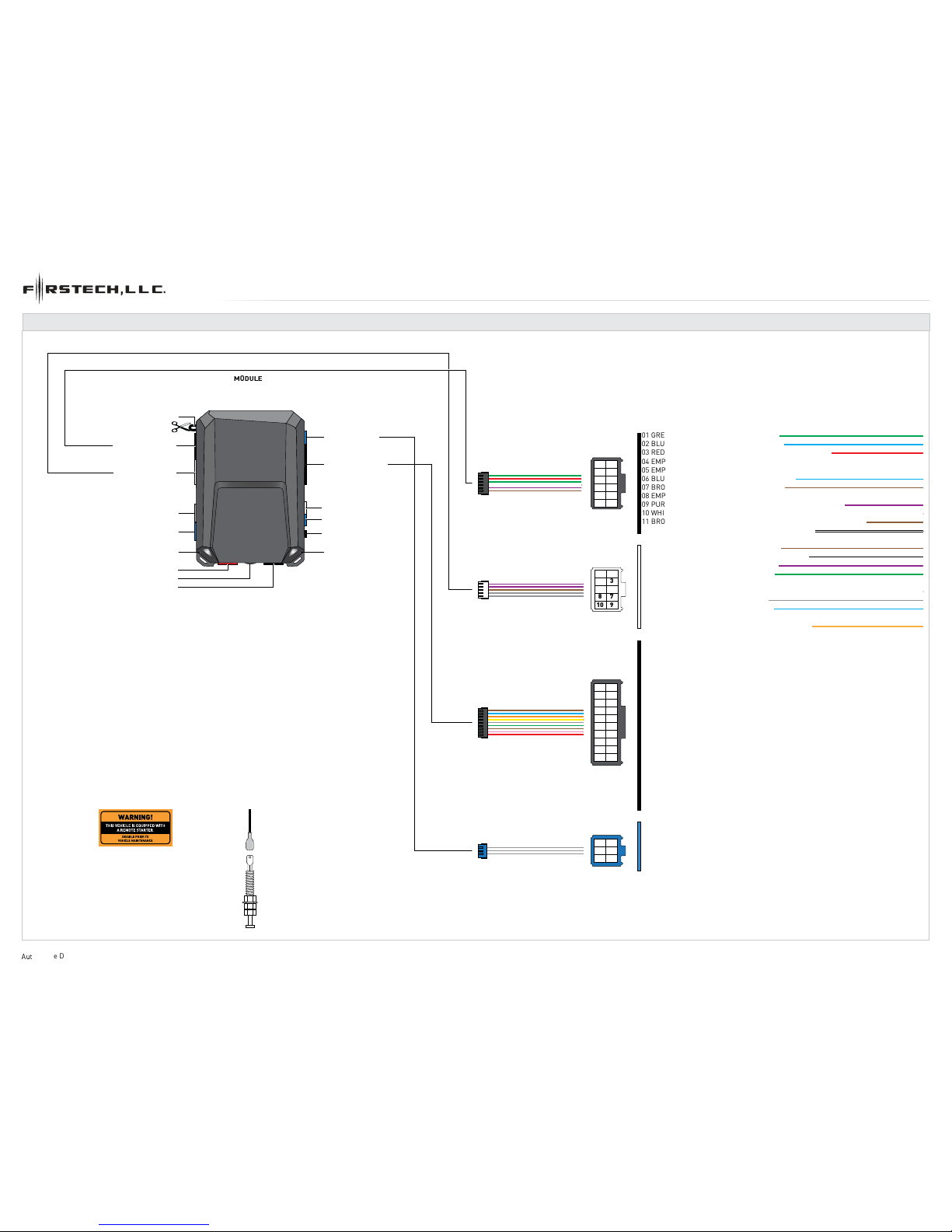
BOX CONTENTS
FT-DAS - 4 PIN RED
RF PORT - 4 PIN BLUE
DRONE - 4 PIN GRAY
2 PIN WHITE - LED
PROGRAMMING BUTTON
2 PIN BLUE - THERMISTOR
LED 1
LED 2
FT-DAS SENSITIVTY ADJUSTMENT DIAL
WEBLINK PORT - 4 PIN BLACK
HOOD SWITCHSTICKERS
7
9
3
10
8
6
4
1
2
5
7
9
3
10
8
11
12
6
4
1
2
5
7
9
3
10
8
11
13
14
12
15
17
18
19
20
16
6
4
1
2
5
4
5
3
2
1
6
M5
M4
01 GREEN•BLACK DOT - LOCK (-) OUTPUT
01 GREEN•BLACK DOT - LOCK (-) OUTPUT
02 BLUE•BLACK DOT - UNLOCK (-) OUTPUT02 BLUE•BLACK DOT - UNLOCK (-) OUTPUT
03 RED/WHITE•BLACK DOT - TRUNK RELEASE (-) OUTPUT
03 RED/WHITE•BLACK DOT - TRUNK RELEASE (-) OUTPUT
04 EMPTY04 EMPTY
05 EMPTY05 EMPTY
06 BLUE/WHITE•BLACK DOT - GWR (-) OUTPUT
06 BLUE/WHITE•BLACK DOT - GWR (-) OUTPUT
07 BROWN•BLACK DOT - SIREN (+) OUTPUT07 BROWN•BLACK DOT - SIREN (+) OUTPUT
08 EMPTY
08 EMPTY
09 PURPLE/BLACK•BLACK DOT - RAP SHUTDOWN (-) OUTPUT09 PURPLE/BLACK•BLACK DOT - RAP SHUTDOWN (-) OUTPUT
10 WHITE/BLACK•BLACK DOT - HORN (-) OUTPUT10 WHITE/BLACK•BLACK DOT - HORN (-) OUTPUT
11 BROWN/BLACK•BLACK DOT - GROUND WHEN ARMED (-) OUTPUT
11 BROWN/BLACK•BLACK DOT - GROUND WHEN ARMED (-) OUTPUT
12 WHITE•BLACK DOT - PARKING LIGHTS (-) OUTPUT
01 BROWN•SILVER DOT - BRAKE (+) INPUT
02 BLACK/WHITE•SILVER DOT - E-BRAKE (-) INPUT
03 PURPLE•SILVER DOT - DOOR (+) INPUT
04 GREEN•SILVER DOT - DOOR (-) INPUT
05 EMPTY
06 WHITE/BLUE•SILVER DOT - X-TRIGGER (-) INPUT
07 GRAY•SILVER DOT - HOOD (-) INPUT
08 BLUE•SILVER DOT - TRUNK (-) INPUT
09 EMPTY
10 TAN•SILVER DOT - EXT ALARM SENSOR (-) INPUT
FUNCTIONS DEFINED BY FIRMWARE
FUNCTIONS DEFINED BY FIRMWARE
M3
M2
M3 - 10 PIN WHITE
M2 - 12 PIN BLACK
M5 - 6 PIN BLUE
M4 - 20 PIN BLACK
2X
BOX CONTENTS - 1 OF 1
www.idatalink.com
A
omotive Data Solutions Inc. © 2016 FT-DC2-S
PAGE 3OF 12
• 20161025

U.S. Patent No. 8,856,780
01
ENGINE
START
STOP
OFF ACC ON STARTSTART
START
02
03
04
05
06
CH PROGRAMMING PROCEDURE - 1 OF 1
S
ART vehicle for 15 seconds.
Press and hold the brake pedal.
Press and release the module’s programming
button. (OR if the remotes are already
programmed to the vehicle, press and hold the
start button of the remote for 2.5 seconds.)
Wait, LED 2 will flash GREEN. (See the Module
Diagnostics page)
Release the brake pedal.
Module Programming Procedure completed.
www.idatalink.comAutomotive Data Solutions Inc. © 2016 FT-DC2-S
PAGE 4 OF 12
• 20161025

U.S. Patent No. 8,856,780
>>
01
02
ENGINE
START
STOP
OFF ACC ON START
ON
03
04
05
06
>>
07
08
ENGINE
START
STOP
OFF ACC ON STARTOFF
09
AFTERMARKET REMOTE PROGRAMMING PROCEDURE - 1 OF 1
W
ogram aftermarket remotes
before usage. A maximum of four [4x]
aftermarket remotes per system.
Time restriction. Complete next step within 7
seconds.
Cycle ignition ON five times [5x OFF/ON]
rapidly.
Parking Light will flash once [1x].
Time restriction. Complete next step within 5
seconds from previous step.
Press once [1x] on LOCK button of aftermarket
remote.
Parking Light will flash once [1x].
To program additional remotes: repeat steps 4
to 6 using each additional remote.
Wait, Parking Light will flash twice [2x].
Turn ignition to OFF position.
Aftermarket Remote Programming Procedure
completed.
www.idatalink.comAutomotive Data Solutions Inc. © 2016 FT-DC2-S
PAGE 5 OF 12
• 20161025
U.S. Patent No. 8,856,780
>>
01
02
ENGINE
START
STOP
OFF ACC ON START
ON
03
04
05
ENGINE
START
STOP
OFF ACC ON STARTOFF
06
>>
VALET MODE PROGRAMMING PROCEDURE - 1 OF 1
N
TE: In Valet Mode, the Remote starter is not
functional. Keyless entry, Lock and Unlock will
remain functional. See RF kit user manual for
alternate valet mode programming.
Time restriction. Complete next step within 7
seconds.
Cycle ignition ON twice [2x OFF/ON] rapidly.
Press and release the BRAKE pedal three
times [3x].
Parking Light will flash once [1x] then will
flash twice [2x].
Set ignition to OFF position.
Valet Mode Programming Procedure
completed.
To exit valet mode: repeat steps 1 to 5.
www.idatalink.comAutomotive Data Solutions Inc. © 2016 FT-DC2-S
PAGE 6 OF 12
• 20161025

U.S. Patent No. 8,856,780
www.idatalink.comAutomotive Data Solutions Inc. © 2016 FT-DC2-S
PAGE 7 OF 12
• 20161025
TIBLE ACCESSORIES - 1 OF 2
MODULE
TELEMATIC PORT
DRONE
(NC)
TELEMATIC KIT (accessory sold separately)
10 11 12 13 14 15 16
12345678
9
WEBLINK MOBILE (accessory sold separately)
MOBILE DEVICE
PORT
OBDII CONNECTOR
4 PIN BLACK CABLE
MODULE
WEBLINK PORT
OBDII CONNECTOR
WEBLINK CABLE (required accessory sold separately)
WEBLINK CABLE
COMPUTER
USB PORT
4 PIN BLACK CABLE
MODULE
WEBLINK PORT
U.S. Patent No. 8,856,780
www.idatalink.comAutomotive Data Solutions Inc. © 2016 FT-DC2-S
PAGE 8 OF 12
• 20161025
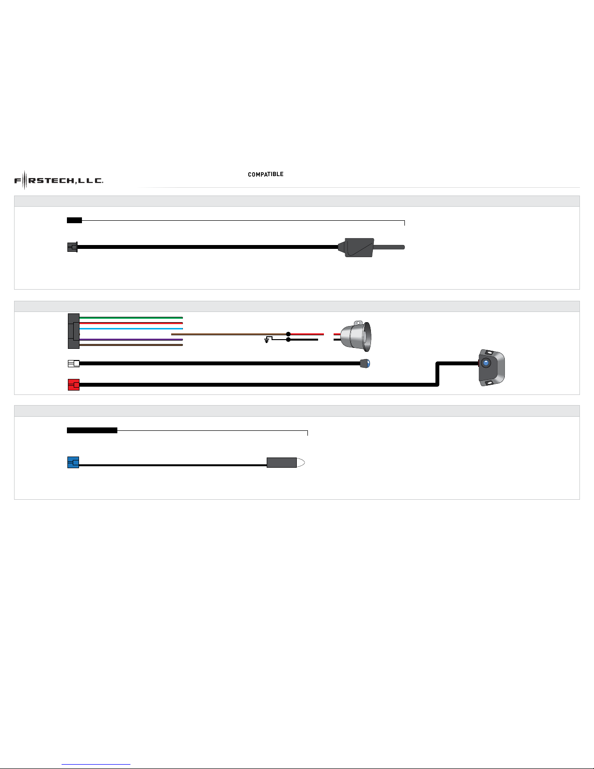
TIBLE ACCESSORIES - 2 OF 2
RF KIT
RF KIT (accessories sold separately)
ANTENNA
MODULE
RF PORT
TEMPERATURE SENSOR
TEMPERATURE SENSOR (accessories sold separately)
MODULE
2 PIN BLUE
07 BROWN•BLACK DOT - SIREN (+) OUTPUT RED
BLACK SIREN
ALARM LED
FT-DAS
MODULE
12 PIN BLACK
MODULE
2 PIN WHITE
MODULE
4 PIN RED
ALARM KIT (accessories sold separately)

U.S. Patent No. 8,856,780
ONLINE MODULE SETTINGS - 1 OF 1
WEB PROGRAMMABLE MENUS DESCRIPTION
MENU 1 – Remote Starter RS related configuration options
MENU 2 – Doorlock Options Convenience feature configuration options
MENU 3 – Security Options Alarm activation and settings
MENU 4 – AUX function assignments Set transmitter AUX buttons controls
MENU 5 – Programmable outputs (POC) Set actions for programmable outputs
MENU 6 – Pulse Timer Output Configuration (PTO) Set duration for pulse timer outputs (if used)
MENU 7 – Input Configurations Set inputs for Auto by firmware/Data/Analog
MENU 8 – Output Configurations Set outputs for Auto by firmware/Data/Analog
Programming options are avaible through Weblink and Weblink Mobile only.
www.idatalink.comAutomotive Data Solutions Inc. © 2016 FT-DC2-S
PAGE 9 OF 12
• 20161025

U.S. Patent No. 8,856,780
MODULE DIAGNOSTICS - 1 OF 1
TEST MODULE
LED 1 STATUS
DIAGNOSTIC
I DURING MODULE PROGRAMMING
Flashing RED Missing/wrong information from firmware or vehicle.
Solid RED Module waiting for more vehicle information.
Flashing GREEN Additional steps required to complete module programming.
Solid GREEN then OFF Module correctly programmed.
OFF No activity or module already programmed.
II DURING TACH PROGRAMMING
1 GREEN flash Tach signal programmed in Analog
2 GREEN flashes Tach signal programmed in Data
3 RED flashes No tach signal detected
4 RED flashes System is in valet mode
5 RED flashes Tach set for ‘VTS’. No tach programming required
6 RED flashes Tach set for ‘assumed start’. No tach programming required
III DURING REMOTE START
Flashing RED Module incorrectly programmed.
Solid RED Module incorrectly programmed.
Flashing GREEN Module correctly programmed and operational.
Solid GREEN then OFF Reset in progress.
OFF Invalid ground when running status from remote starter.
IV WITH IGNITION OFF
Flashing RED Module incorrectly programmed or connected.
Solid RED Module not programmed. Waiting for more vehicle information.
Flashing GREEN False ground when running status from remote starter.
Solid GREEN then OFF Reset in progress.
OFF Module at rest and ready for a remote start sequence.
www.idatalink.comAutomotive Data Solutions Inc. © 2016 FT-DC2-S
PAGE 10 OF 12
• 20161025
U.S. Patent No. 8,856,780
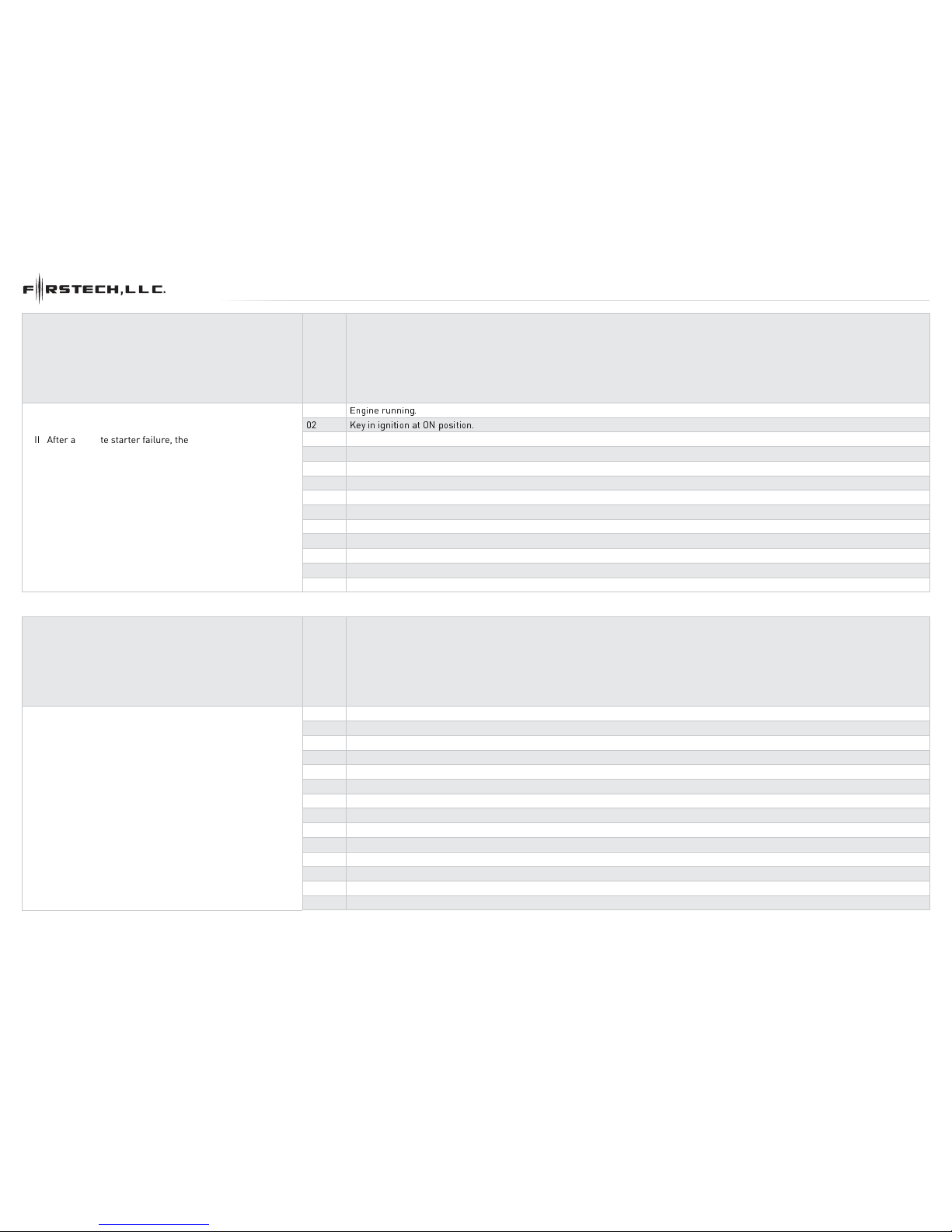
REMOTE STARTER ERROR CODES - 1 OF 1
REMOTE STARTER ERROR CODES:
NOTES
[X] NUMBER OF
PARKING LIGHT
FLASHES
DIAGNOSTIC
I WARNING: The following applies only when the parking
lights are connected and supported by the system.
01
E ! "# $
02 Ke
y
%
&
'% () *&+
%
&
$
II After a remote starter failure, the parking lights will fl ash
three [3x] times, then will fl ash [X] number times to
indicate an error code. See table.
03 Door is open.
04 Trunk is open.
05 Foot brake is ON.
06 Hood is open.
07 The reservation is OFF. (Manual transmission only)
08 Tach failure.
09 The vehicle is moving (VSS).
10 System is in Valet Mode.
11 CAN communication failure
12 RS not synchronized. Start vehicle with OEM key for 15 sec before trying a new RS sequence.
13 Bypass problem.
REMOTE STARTER SHUTDOWN ERROR CODES:
NOTES
[Y] NUMBER OF
PARKING LIGHT
FLASHES
DIAGNOSTIC
I WARNING: The following applies only when the parking
lights are connected and supported by the system.
01 Engine tach signal is lost.
02 Emergency brake is lost.
II If the engine shuts down after a remote starter sequence:
Press and hold the Trunk button and the Start button at the
same time for 2.5 seconds when using a 1-WAY remote.
OR
Press once [1x] on button “4” when using a 2-WAY remote.
The parking lights will flash four [4x] times, then will flash
[Y] number times to indicate an error code. See table.
03 Foot brake is ON.
04 Hood is open.
05 Engine RPM limiter is ON.
06 Glow plug timeout error.
07 Vehicle is moving (VSS).
08 N/A
09 N/A
10 Door is open.
11 CAN communication failure during RS sequence.
12 RS not synchronized. Start vehicle with OEM key for 15 sec before trying a new RS sequence.
13 Takeover is not allowed.
14 Shutdown error, board overheat protection.
www.idatalink.comAutomotive Data Solutions Inc. © 2016 FT-DC2-S
PAGE 11 OF 12
• 20161025

U.S. Patent No. 8,856,780
>>
01
02
03
04
05
06
07
08
>>
MODULE RESET PROCEDURE - 1 OF 1
T,- .
ollo
w/01 23
ocedure resets the module
programming to the vehicle. It does not reset
any settings configured online.
Disconnect all connectors from module except
the M1 BLACK 8-pin connector and the M4
BLACK 20-pin connector.
Disconnect the M1 BLACK 8-pin connector
and the M4 BLACK 20-pin connector.
PRESS AND HOLD the module’s programming
button while connecting the M1 BLACK
8-pin connector and the M4 BLACK 20-pin
connector.
Wait, LED 1 will flash RED. RELEASE
programming button.
LED 1 will turn RED for 2 seconds.
Module RESET completed.
Reconnect all connectors.
Repeat programming procedure.
Failure to follow procedure may result with a
DTC or a CHECK ENGINE error message.
www.idatalink.comAutomotive Data Solutions Inc. © 2016 FT-DC2-S
PAGE 12 OF 12
• 20161025

U.S. Patent No. 8,856,780
20161212
REVISION DATE
FT-RSA-FO1B-[FT-DC2-S]
FIRMWARE
FT-DC2-S
HARDWARE
ADS-USB (OPTIONAL)
ADS-WLM-AN1/ADS-WLM-AP1 (OPTIONAL)
DRONE MOBILE DR-2000 (OPTIONAL)
COMPATIBLE RF-KIT (OPTIONAL)
ACCESSORIES
DOCUMENT NUMBER
2011-2014 FORD EDGE STD KEY AT
www.idatalink.comAutomotive Data Solutions Inc. © 2016
INSTALL GUIDE
NOTICE
The manufacturer will accept no responsability for any electrical damage resulting from
improper installation of this product, be that either damage to the vehicle itself or to the
installed device. This device must be installed by a certified technician. Please review the
Installation Guide carefully before beginning any work.
T001_H
T-HARNESS / COMPONENT LOCATOR - 1 OF 1
A
B
D
C
PAGE 2 OF 10
U.S. Patent No. 8,856,780 2011-2014 Ford Edge STD key AT
www.idatalink.comAutomotive Data Solutions Inc. © 2016 FTRSAFO1BFTDC2SEN
20161212
87A
30
87
85
86
!
MS2
MS1
VS2VS2
VS1VS1
VS4VS4
VS3VS3
1
1
10 11 12 13 14 15 16
123
11
345678
9
10 11 12 13
14 15 16 17 18 19 20 21 22 23 24 25 26
1 2 34 5 678 9
10
12345
67 8 9
1 2 3 4 5 6 78
123
4 5 6
T001_H
CUT LOOP FOR AUTOMATIC TRANSMISSION ONLYCUT LOOP FOR AUTOMATIC TRANSMISSION ONLY
GREEN/PURPLE
GREEN/WHITE
BROWN/YELLOW
BROWN/RED
19 RED19 RED
2020
0101
0202
0303
0404
0505
0606
0707
0808
0909
1010
1111
1212
1313
1414
1515
1616
1717
1818
0101
0202
0303
0404
0505
0606
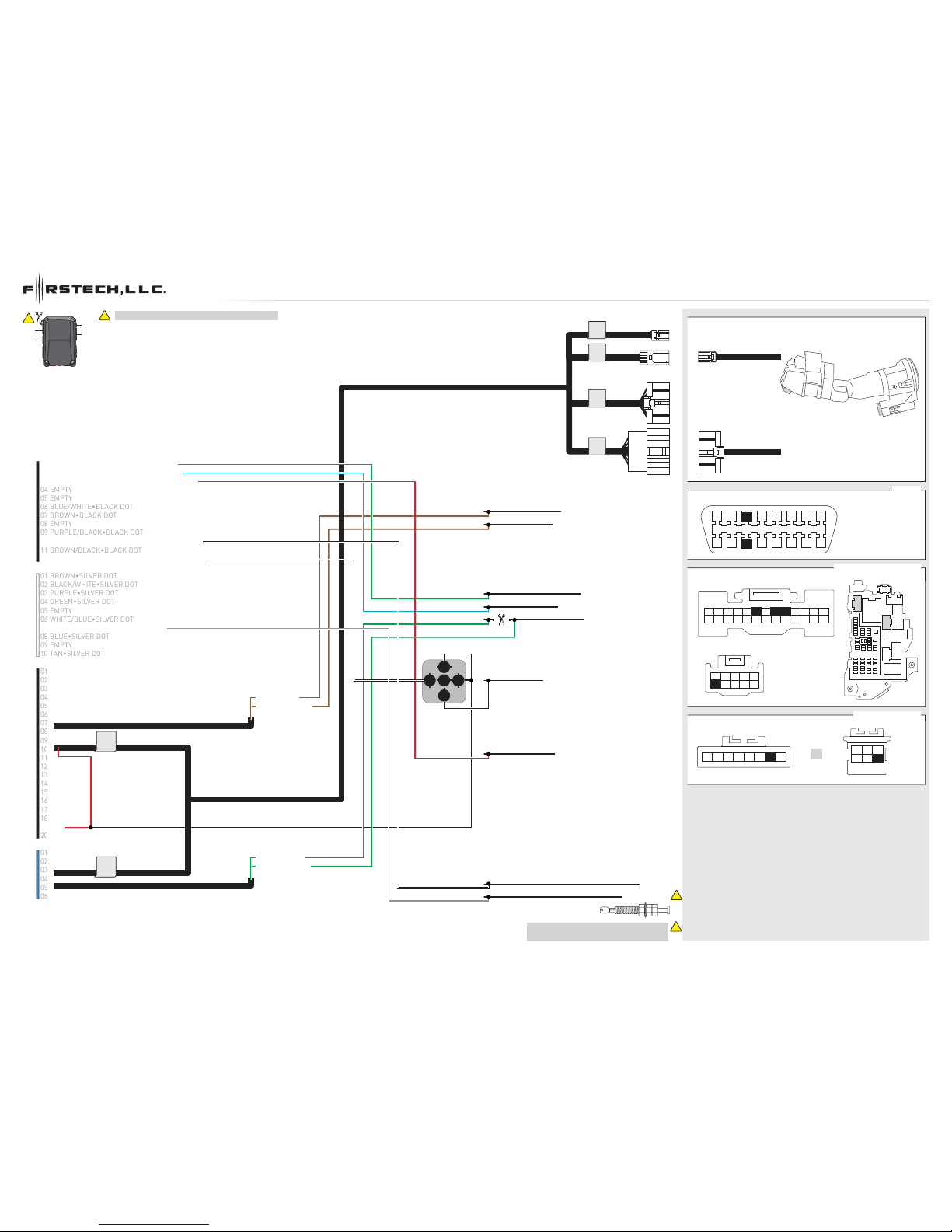
T-HARNESS / WIRING DIAGRAM - 1 OF 1
1
M5
M4
M2
M3
04 EMPTY04 EMPTY
1: BLACK
2: GRAY
1: BLACK
BCM, DRIVER SIDE DASH (C)
LIFTGATE SWITCH (D)
CANH (DATA) GRAY/ORANGE - 03
CANL (DATA) PURPLE/ORANGE - 11
LOCK (-) BLUE/GREEN - 06
TRUNK RELEASE (-) GRAY/YELLOW
UNLOCK (-) YELLOW/PURPLE - 08
DRIVER DOOR PIN (OPEN)
GREEN/PURPLE - 09
PARKING LIGHT (+) YELLOW/BLUE - 06
OBDII (B)
06 BLUE/WHITE•BLACK DOT06 BLUE/WHITE•BLACK DOT
08 EMPTY
01 GREEN•BLACK DOT - LOCK (-) OUTPUT01 GREEN•BLACK DOT - LOCK (-) OUTPUT
02 BLUE•BLACK DOT - UNLOCK (-) OUTPUT02 BLUE•BLACK DOT - UNLOCK (-) OUTPUT
03 RED/WHITE•BLACK DOT - TRUNK (-) OUTPUT
03 RED/WHITE•BLACK DOT - TRUNK (-) OUTPUT
05 EMPTY05 EMPTY
07 BROWN•BLACK DOT07 BROWN•BLACK DOT
09 PURPLE/BLACK•BLACK DOT09 PURPLE/BLACK•BLACK DOT
11 BROWN/BLACK•BLACK DOT11 BROWN/BLACK•BLACK DOT
12 WHITE•BLACK DOT - PARKING LIGHT (-) OUTPUT12 WHITE•BLACK DOT - PARKING LIGHT (-) OUTPUT
01 BROWN•SILVER DOT01 BROWN•SILVER DOT
02 BLACK/WHITE•SILVER DOT02 BLACK/WHITE•SILVER DOT
03 PURPLE•SILVER DOT03 PURPLE•SILVER DOT
04 GREEN•SILVER DOT04 GREEN•SILVER DOT
05 EMPTY05 EMPTY
06 WHITE/BLUE•SILVER DOT06 WHITE/BLUE•SILVER DOT
08 BLUE•SILVER DOT08 BLUE•SILVER DOT
09 EMPTY09 EMPTY
10 TAN•SILVER DOT10 TAN•SILVER DOT
07 GRAY•SILVER DOT - HOOD (-) INPUT07 GRAY•SILVER DOT - HOOD (-) INPUT
10 WHITE/BLACK•BLACK DOT - HORN (-) OUTPUT10 WHITE/BLACK•BLACK DOT - HORN (-) OUTPUT
HORN (-)
HOOD SWITCH
INSTALL THE SUPPLIED HOOD SWITCH IF
THE VEHICLE IS NOT EQUIPPED WITH ONE.
1
2
1: IMMOBILIZER CONNECTOR
1: IMMOBILIZER HARNESS
2: IGNITION CONNECTOR
2: IGNITION HARNESS
2
1
OR
!
M3
M2 M5
M4
PAGE 3 OF 10
U.S. Patent No. 8,856,780 2011-2014 Ford Edge STD key AT
www.idatalink.comAutomotive Data Solutions Inc. © 2016 FTRSAFO1BFTDC2SEN
20161212

T001_W
HARDWIRE / COMPONENT LOCATOR - 1 OF 1
A
B
D
C
PAGE 4 OF 10
U.S. Patent No. 8,856,780 2011-2014 Ford Edge STD key AT
www.idatalink.comAutomotive Data Solutions Inc. © 2016 FTRSAFO1BFTDC2SEN
20161212
87A
30
87
85
86
!
1
1
10 11 12 13 14 15 16
123
11
345678
9
10 11 12 13
14 15 16 17 18 19 20 21 22 23 24 25 26
1 2 34 5 678 9
OR
10
12345
67 8 9
1 2 3 4 5 6 78
123
4 5 6
1472 3 5 6
1 2 3 4
T001_W
CUT LOOP FOR AUTOMATIC TRANSMISSION ONLYCUT LOOP FOR AUTOMATIC TRANSMISSION ONLY
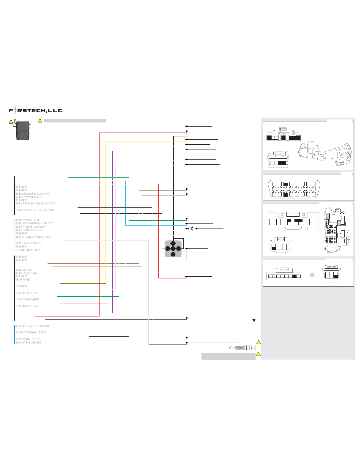
HARDWIRE / WIRING DIAGRAM - 1 OF 1
1
M5
M4
M2
M3
04 EMPTY04 EMPTY
03 BROWN/RED - CANH 103 BROWN/RED - CANH 1
04 BROWN/YELLOW - CANL 104 BROWN/YELLOW - CANL 1
1: BLACK
2: GRAY
1: BLACK
BCM, DRIVER SIDE DASH (C)
LIFTGATE SWITCH (D)
CANH (DATA) GRAY/ORANGE - 03
IGNITION 1 (+) WHITE/ORANGE - 01
ACCESSORY (+) PURPLE/GREEN - 06
RX (DATA) PURPLE/GRAY - 04
TX (DATA) YELLOW/ORANGE - 03
CANL (DATA) PURPLE/ORANGE - 11
LOCK (-) BLUE/GREEN - 06
TRUNK RELEASE (-) GRAY/YELLOW
UNLOCK (-) YELLOW/PURPLE - 08
DRIVER DOOR PIN (OPEN)
GREEN/PURPLE - 09
PARKING LIGHT (+) YELLOW/BLUE - 06
1
2
IGNITION SWITCH (A)
OBDII (B)
12V (+) GREEN/RED - 04
KEYSENSE (+) BLUE/GRAY - 05
STARTER 1 (+) BLUE/WHITE - 07
06 BLUE/WHITE•BLACK DOT06 BLUE/WHITE•BLACK DOT
08 EMPTY
01 GREEN•BLACK DOT - LOCK (-) OUTPUT01 GREEN•BLACK DOT - LOCK (-) OUTPUT
02 BLUE•BLACK DOT - UNLOCK (-) OUTPUT02 BLUE•BLACK DOT - UNLOCK (-) OUTPUT
03 RED/WHITE•BLACK DOT - TRUNK (-) OUTPUT
03 RED/WHITE•BLACK DOT - TRUNK (-) OUTPUT
05 EMPTY05 EMPTY
07 BROWN•BLACK DOT07 BROWN•BLACK DOT
09 PURPLE/BLACK•BLACK DOT09 PURPLE/BLACK•BLACK DOT
11 BROWN/BLACK•BLACK DOT11 BROWN/BLACK•BLACK DOT
12 WHITE•BLACK DOT - PARKING LIGHT (-) OUTPUT12 WHITE•BLACK DOT - PARKING LIGHT (-) OUTPUT
01 BROWN•SILVER DOT01 BROWN•SILVER DOT
02 BLACK/WHITE•SILVER DOT02 BLACK/WHITE•SILVER DOT
03 PURPLE•SILVER DOT03 PURPLE•SILVER DOT
04 GREEN•SILVER DOT04 GREEN•SILVER DOT
05 EMPTY05 EMPTY
06 WHITE/BLUE•SILVER DOT06 WHITE/BLUE•SILVER DOT
08 BLUE•SILVER DOT08 BLUE•SILVER DOT
09 EMPTY09 EMPTY
10 TAN•SILVER DOT10 TAN•SILVER DOT
01 EMPTY01 EMPTY
02 EMPTY02 EMPTY
05 BLUE/RED05 BLUE/RED
06 BLUE/YELLOW06 BLUE/YELLOW
07 EMPTY07 EMPTY
08 ORANGE08 ORANGE
09 YELLOW - KEYSENSE (+) OUTPUT09 YELLOW - KEYSENSE (+) OUTPUT
10 EMPTY10 EMPTY
11 GRAY/RED - IMMO. RX (DATA)11 GRAY/RED - IMMO. RX (DATA)
12 GRAY/YELLOW12 GRAY/YELLOW
13 GREEN/RED - IMMO. TX (DATA)13 GREEN/RED - IMMO. TX (DATA)
14 ORANGE/WHITE14 ORANGE/WHITE
15 BROWN - ACCESSORY (+) IN/OUT15 BROWN - ACCESSORY (+) IN/OUT
16 ORANGE/BLACK16 ORANGE/BLACK
17 PINK - IGNITION (+) IN/OUT17 PINK - IGNITION (+) IN/OUT
18 PURPLE - STARTER (+) OUTPUT18 PURPLE - STARTER (+) OUTPUT
19 RED - 12V (+)19 RED - 12V (+)
20 BLACK - GROUND (-)20 BLACK - GROUND (-)
01 GRAY/BLACK•BLUE DOT01 GRAY/BLACK•BLUE DOT
02 WHITE/BLACK•BLUE DOT - DDP (OPEN) VEHICLE SIDE02 WHITE/BLACK•BLUE DOT - DDP (OPEN) VEHICLE SIDE
03 GRAY/RED•BLUE DOT03 GRAY/RED•BLUE DOT
04 WHITE/RED•BLUE DOT - DDP (OPEN) CONNECTOR SIDE04 WHITE/RED•BLUE DOT - DDP (OPEN) CONNECTOR SIDE
05 GRAY•BLUE DOT05 GRAY•BLUE DOT
06 WHITE•BLUE DOT06 WHITE•BLUE DOT
07 GRAY•SILVER DOT - HOOD (-) INPUT07 GRAY•SILVER DOT - HOOD (-) INPUT
10 WHITE/BLACK•BLACK DOT - HORN (-) OUTPUT10 WHITE/BLACK•BLACK DOT - HORN (-) OUTPUT
HORN (-)
HOOD SWITCH
INSTALL THE SUPPLIED HOOD SWITCH IF
THE VEHICLE IS NOT EQUIPPED WITH ONE.
1
2
1
2
!
M3
M2 M5
M4
PAGE 5 OF 10
U.S. Patent No. 8,856,780 2011-2014 Ford Edge STD key AT
www.idatalink.comAutomotive Data Solutions Inc. © 2016 FTRSAFO1BFTDC2SEN
20161212
>>
01
OFF
ACC ON
START
02
OFF
ACC ON
START
03
04
OFF
ACC ON
START
05
OFF
ACC ON
START
06
OFF
ACC ON
START
07
OFF
ACC ON
START
08
09
10
OFF
ACC ON
START
11
OFF
ACC ON
START
12
OFF
ACC ON
START
13
14
15
OFF
ACC ON
START
16
>>
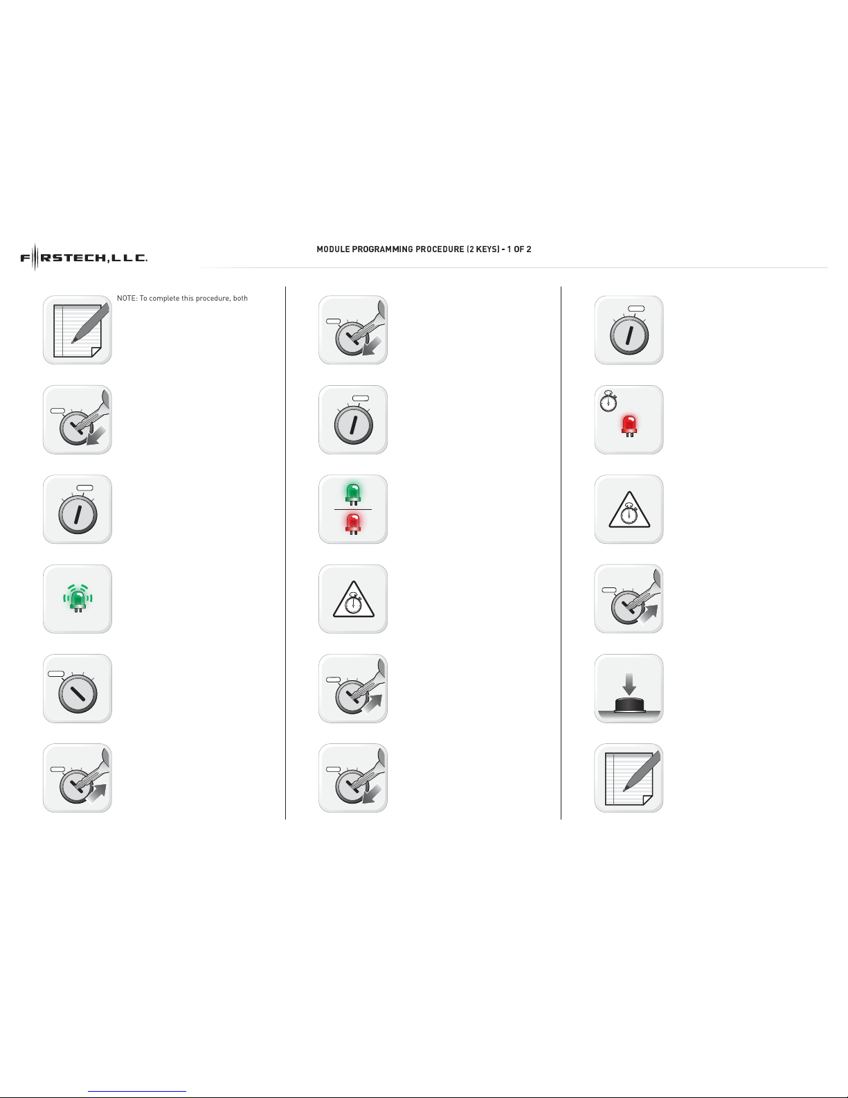
✤✁✂✄☎ ✆✝✞✝✟✤✤✠✡✞ ✆✝☛☎✁✂✝☎ ☞✌ ✍☎✎✏✑ ✒ ✓ ✔ ✌
NOTE: To complete this procedure, both OEM
keys are required.
Insert key 1 into ignition.
Turn key 1 to ON position. LED 1 will turn solid
RED.
Wait, LED 1 will flash GREEN. (This may take
up to 30 seconds)
Turn key 1 to OFF position.
Remove key 1.
Insert key 1 into ignition.
Turn key 1 to ON position.
If LED 1 turns solid GREEN for 2 seconds:
Module Programming Procedure completed. If
LED 1 turns solid RED, proceed with following
step.
TIME RESTRICTION. Complete steps 08 to 10
within 4 seconds after LED 1 turns OFF.
Remove key 1.
Insert key 2 into ignition.
Turn key 2 to ON position.
Wait, LED 1 will turn solid RED then will turn
OFF.
TIME RESTRICTION. Complete steps 13 and 14
within 4 seconds after LED 1 turns OFF.
Remove key 2.
Press and release programming button.
If the LED 1 begins to flash RED, you are using
a cloned key or used the same key twice.
PAGE 6 OF 10
U.S. Patent No. 8,856,780 2011-2014 Ford Edge STD key AT
www.idatalink.comAutomotive Data Solutions Inc. © 2016 FTRSAFO1BFTDC2SEN
20161212
17
18
OFF
ACC ON
START
19
20
21
22
23
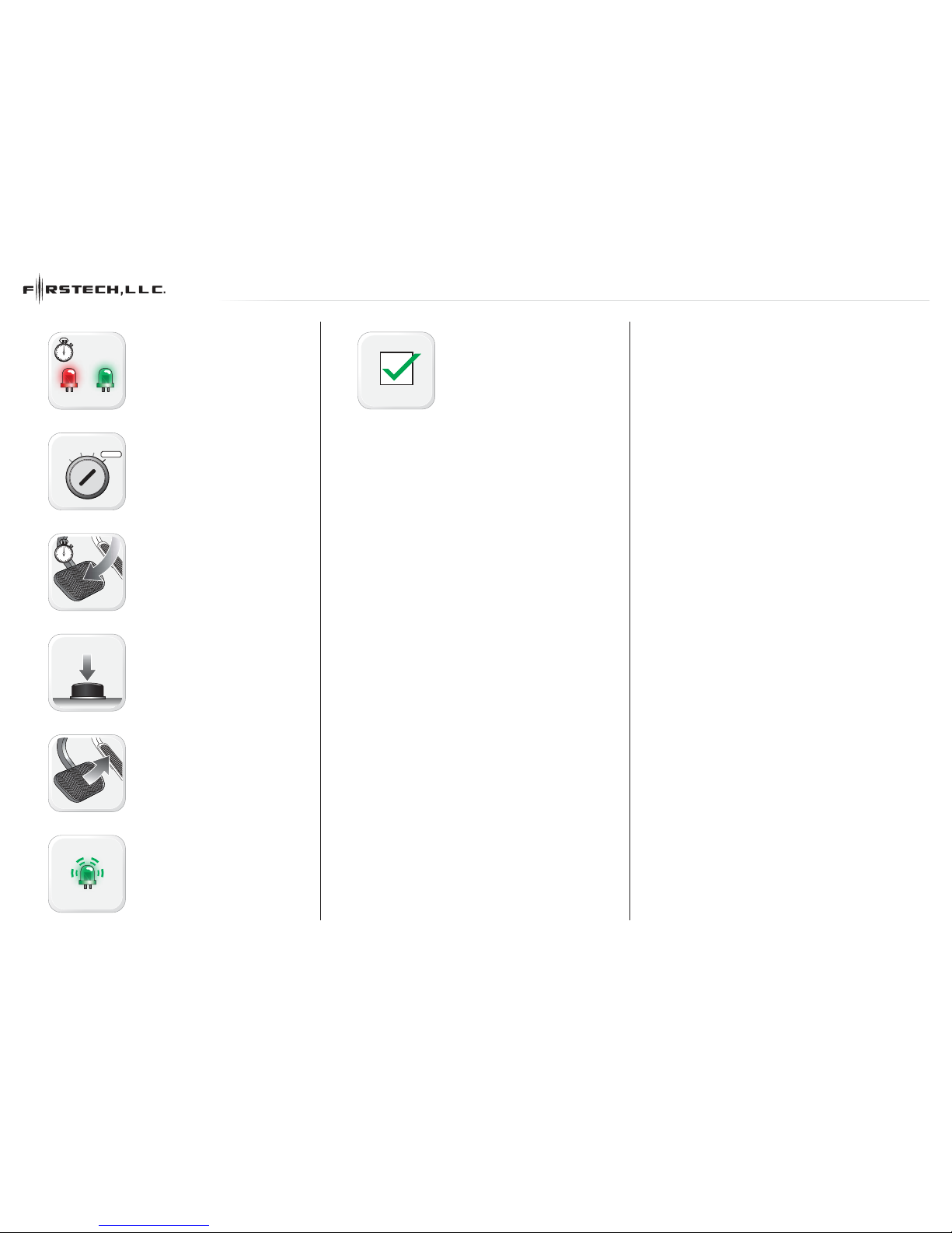
MODULE PROGRAMMING PROCEDURE (2 KEYS) - 2 OF 2
Wait, LED 1 will turn solid RED then will turn
solid GREEN.
START vehicle for 15 seconds.
Press and hold the brake pedal.
Press and release the module’s programming
button.
Release the brake pedal.
Wait, LED 2 will flash GREEN.
Module Programming Procedure completed.
PAGE 7 OF 10
U.S. Patent No. 8,856,780 2011-2014 Ford Edge STD key AT
www.idatalink.comAutomotive Data Solutions Inc. © 2016 FTRSAFO1BFTDC2SEN
20161212
>>
01
02
ENGINE
START
STOP
OFF ACC ON START
ON
03
04
>>
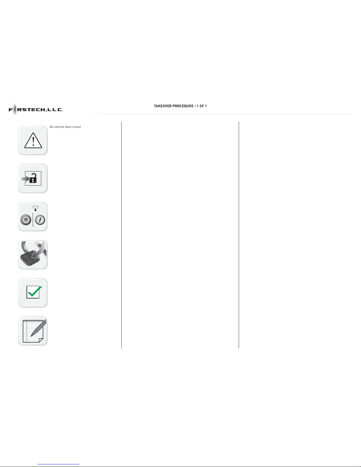
✕✣✖✗✘✚✗✙ ✛✙✘✜✗✢ ✙✗ ✦ ✧ ✘★ ✧
All vehicle doors must be closed and locked
prior to remote start sequence.
Press unlock on OEM or aftermarket remote
or request switch.
DO NOT PRESS BRAKE PEDAL. Set ignition to
ON position. Wait 2 seconds for key validation.
Press and release BRAKE pedal.
Take over procedure completed.
Failure to follow procedure will result in
vehicle engine shutdown.
PAGE 8 OF 10
U.S. Patent No. 8,856,780 2011-2014 Ford Edge STD key AT
www.idatalink.comAutomotive Data Solutions Inc. © 2016 FTRSAFO1BFTDC2SEN
20161212
Table of contents
Other Firstech, LLC. Remote Starter manuals


 User manual")


