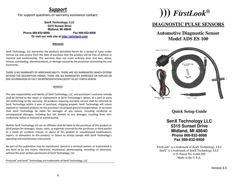
FirstLook ADS ES 300 User manual

DIAGNOSTIC PULSE SENSORS
Automotive Injector Diagnostic Sensor
Quick Setup Guide
Model ADS ES 300
SenX Technology
5315 Sunset Drive
Midland, MI 48640
www.senxtech.com
Phone 1 866 832 8898
U.S. Patent Nos. 6,484,589 & 6,609,416
Version 2.1
FirstLook®

2
The supplied quick disconnect fittings allow the FirstLook®Fuel
Injection Sensor to be used with virtually any commercially
available Fuel Pressure Test Kit and adaptors.
Using the FirstLook®sensor is in addition to the necessary electrical tests
that need to be performed before condemning any injector. This sensor
checks flow of a given injector. With that said low flow can come from
a voltage drop in the injector circuit, or a faulty driver in the PCM. The use
of a low amps current probe and or a voltage drop test to confirm circuit
integrity is crucial to get the full picture of what is going on with any
injector. Remember low flow can be caused by an electrical problem as
well as a flow problem within the injector. It is up to you to determine
where the low flow problem area is. What this sensor does is locate which
injector is having the problem. To get the whole picture one needs to
know both the electrical and the physical information to make this
decision. This sensor will finally give you the piece of the puzzle you have
never had before.
IMPORTANT: The sample line and sensing cavity must be
purged of air for the signal to be a true reaction to pressure
changes in the fuel rail.
The physical difference between injectors.
It is important to discuss some of what you might find using
this sensor to head off any false conclusions.
First, practice on a
known good vehicle. Depending on how you trigger your scope (#1
injector, #1 ignition or cam sensor) you will notice that #l injector can
start from before the trigger point or after the trigger point. The best
way to know for sure is to have the correct firing order for the engine.
Next with the key off, disconnect one of the injectors. Follow the firing
order and see if the pattern reflects the cylinder you think it is. With this
confirmed you can be very confident you have located the problem
injector. Now it is up to you to diagnose if it is the injector itself or an
electrical problem with the harness or PCM.
You will find that with practice you will develop your own routine procedure
depending on whether you favor using a current ramping probe, ignition
or even voltage signature to sync the firing order of the injectors.
Connect FirstLook® Injection Sensor using the quick disconnect fitting
supplied in the kit and when necessary the appropriate fitting from your
fuel pressure test kit to connect to the fuel injection rail of vehicle being
tested.

3
WARNINGS
DO NOT MODIFY THE SENSOR AND CONNECTOR
ASSEMBLY
DO NOT USE ON DIESEL ENGINES
ALWAYS WEAR OSHA APPROVED EYE PROTECTION
NO SMOKING, NO OPEN FLAMES, NO ELECTRICAL
SPARKS
USE EXPLOSION PROOF ELECTRICAL DROPLIGHTS
LOOSEN GAS CAP AND RELIEVE FUEL PUMP
PRESSURE
TIGHTEN ALL CONNECTIONS TO ELEMINATE
LEAKS
AVOID FUEL CONTACT WITH HOT ENGINE PARTS
FOLLOW OUR INSTRUCTIONS AND AUTO MAKERS
TEST PROCEDURES
WRAP ADAPTER IN SHOP TOWEL BEFORE
DISCONNECTING
WIPE UP FUEL SPILLS AND PUT RAGS IN APPROVED
CONTAINER
REMOVE ANY FUEL IN THE SENSOR HOSE BEFORE
STORING

4
Turn ignition on and check for leaks. If no leaks are detected
proceed with tests.
The best way to understand how the FirstLook® Fuel Injection Sensor works
is to start with a known good engine. See how the injectors work at both
idle and during the 1500 RPM load test. Next disable an injector and run the
same test. Always remember injector problems can also be caused by a bad
electrical driver. It is just as important to know the electrical condition of
your injectors as it is to know their mechanical condition. Current ramp
testing of the fuel injector electrical system is the best way to verify proper
electrical condition. An engine with oversize fuel rails can cause you to see
two different sets of patterns. The injectors closest to you will appear to have
different waveforms than the injectors on the opposite side of the engine.
Remember what you are looking for is a repeatable pattern. The Nissan
fuel rail below notes this type of waveform. The firing order here is 1-2-3-
4-5-6. You will see 1, 3, 5 appear differently than 2, 4, and 6. This is a
normal condition on many cars. The bad injector is marked between
the
cursers. See
www.senxtech.com
for more.

5
Scope settings for Idle Test
Idle test... 650 to 700 RPM...Scope settings.
Voltage settings... +1 Volts to —1 Volts
Time base ... 200 ms
Start engine and allow to warm up to operational temperature. Observe wave
forms for irregular injector operation.
Good injector waveform not triggered
96 Jeep 6 Cylinders
96 Accord 2.2 bad injector triggered from injector #1

6
Scope settings for 1500 RPM...Power Brake Test
Power brake test...1500 RPM...Scope settings.
Voltage settings... +1 volts to -1 Volts
Time base...100ms
Put vehicle in gear and
apply brakes,
slowly increase RPM to 1500. Most flow
problems will show up as irregularities in the scope pattern at 1500 RPM.
Good waveform not triggered 96 Jeep 6 Cylinders
96 Honda Accord 2.2 Bad Injector triggered from Injector #1

7
For most complete view of Fuel Injection System.
1. Trigger scope using injector #1 as reference point
2. Connect low current probe to the wire feeding voltage to the injectors.
3. Hook up FirstLook® Fuel Injection Sensor to fuel rail.
Run both Idle test and 1500 RPM Power Brake test. This lets you look at
the system at idle and under a working load. With the current probe
hooked to the main line supplying voltage to the injectors you also can see
the current draw conditions for the injectors. The current draw waveforms
will track with the injector pulse wave forms allowing you a complete look at
the fuel injector system and helping to determine if problem is electrical
drivers or actual fuel flow issues with the injectors.
Trigger Current Probe FirstLook®Sensor

8
Support
For support questions or warranty assistance contact:
SenX Technology
5315 Sunset Drive
Midland, MI 48640
Phone 866 832 8898 Fax 989-832-8908
Or visit our website at www.senxtech.com
Warranty
SenX Technology, LLC warranties the products described herein for a period of 1 year
under normal use and service from the date of purchase, that the product will be free of
defects in material and workmanship. This warranty does not cover ordinary wear and
tear, abuse, misuse, overloading, altered products, or damage caused by the purchaser
connecting the unit incorrectly.
THERE IS NO WARRANTY OF MERCHANTABILITY. THERE ARE NO WARRANTIES WHICH
EXTEND BEYOND THE DESCRIPTION HEREIN. THERE ARE NO WARRANTIES EXPRESSED OR
IMPLIED OR ANY AFFIRMATION OF FACT OR REPRESENTATION EXCEPT AS SET FORTH
HEREIN.
REMEDY
SenX Technology, LLC sole responsibility and liability, and purchaser's exclusive
remedy shall be limited to the repair or replacement at SenX Technology option,
of a part or parts not conforming to the warranty. All products requiring warranty
service shall be returned to SenX Technology within I year of purchase, shipping
prepaid. SenX Technology will return repaired or replaced products to the
purchaser via prepaid ground transportation. In no event shall SenX Technology
be liable for damages of any nature, including incidental or consequential
damages, including but not limited to any damages resulting from non-conformity,
defect in material or workmanship.
Neither SenX Technology LLC nor its affiliates shall be liable to the purchaser of
this product or third parties for damages, losses, costs, or expenses incurred by
the purchaser or third parties as a result of: accident, misuse, or abuse of this product
or unauthorized modifications, repairs or alterations to this product, or failure to
strictly comply with SenX Technology's operating and maintenance instructions.
FirstLook®and SenX®Technology are trademarks of SenX Technology, LLC
No part of this publication may be reproduced, stored in a retrieval system, or
transmitted in any form or by any means, electronic, mechanical, photocopying,
recording, or otherwise, without the prior written permission of SenX Technology, LLC.
Table of contents
Other FirstLook Accessories manuals
Popular Accessories manuals by other brands
Leviton
Leviton O3C15-IDW Installation instructions and owner's manual
Philio Technology Corporation
Philio Technology Corporation PAT12-A manual
LEGRAND
LEGRAND 6 547 40 quick start guide
culiau
culiau Customizer user manual
Rohde & Schwarz
Rohde & Schwarz R&S NRQ6 user manual

STEINEL
STEINEL IS 2180 ECO installation instructions

Siemens
Siemens SIMATIC RF300 System manual
Rechner Sensors
Rechner Sensors N-132/1-10 Operating instuructions
Davis Instruments
Davis Instruments Grounding Kit install guide
Seifert
Seifert SlimLine Pro KG 8512 instruction manual
Intec
Intec CI-24 installation guide
Waterpik
Waterpik WP-100 Series user manual
