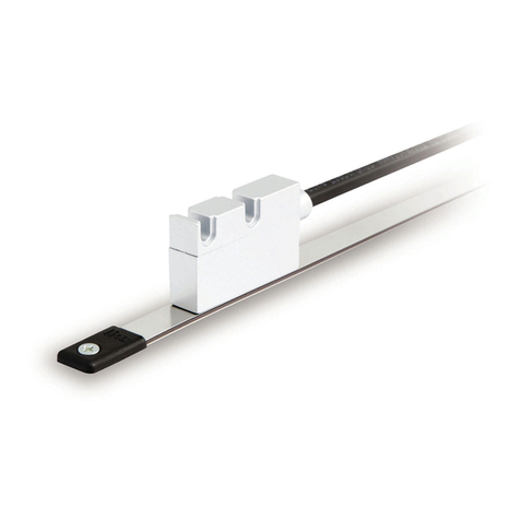
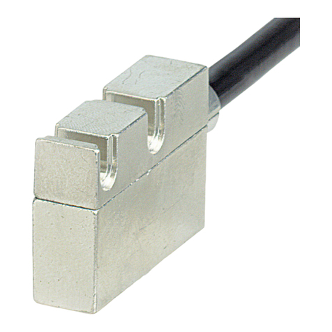
Lika SMAX-BG series User manual

User's guide
SMAX
•Cost-effective absolute linear encoder
•Measuring length up to 600 mm / 3.6 ”
•Resolution down to 0.1 mm
•SSI and voltage/current analogue interfaces
•Up to IP69K protection rate
Suitable for the following models:
•SMAX-BG-...
•SMAX-GG-...
•SMAX-AI1-...
•SMAX-AV -...
Table of Contents
1 - Safety summary 7
- Identification 8
3 - Mounting instructions 9
4 - SSI interface 13
5 - Analogue interface 0
6 - Diagnostic LED 8
7 - Maintenance 9
8 - Troubleshooting 30
Smart encoders & actuators

This publication was produced by Lika Electronic s.r.l. 2017. All rights reserved. Tutti i diritti riservati. Alle Rechte vorbehalten. Todos los
derechos reservados. Tous droits r serv s.
This document and information contained herein are the property of Lika Electronic s.r.l. and shall not be reproduced in whole or in
part without prior written approval of Lika Electronic s.r.l. Translation, reproduction and total or partial modification (photostat copies,
film and microfilm included and any other means) are forbidden without written authorisation of Lika Electronic s.r.l.
The information herein is subject to change without notice and should not be construed as a commitment by Lika Electronic s.r.l. Lika
Electronic s.r.l. reserves the right to make all modifications at any moments and without forewarning.
This manual is periodically reviewed and revised. As required we suggest checking if a new or updated edition of this document is
available at Lika Electronic s.r.l.'s website. Lika Electronic s.r.l. assumes no responsibility for any errors or omissions in this document.
Critical evaluation of this manual by the user is welcomed. Your comments assist us in preparation of future documentation, in order
to make it as clear and complete as possible. Please send an e-mail to the following address [email protected] for submitting your
comments, suggestions and criticisms.

Table of Contents
User's guide......................................................................................................................................................... 1
Table of Contents............................................................................................................................................... 3
Typographic and iconographic conventions.................................................................................................5
Preliminary information.................................................................................................................................... 6
1 - Safety summary....................................................................................................................................... 7
1.1 Safety......................................................................................................................................................................................7
1.2 Electrical safety...................................................................................................................................................................7
1.3 Mechanical safety..............................................................................................................................................................8
- Identification............................................................................................................................................ 8
3 - Mounting instructions............................................................................................................................ 9
3.1 Overall dimensions............................................................................................................................................................9
3.2 Magnetic tape.....................................................................................................................................................................9
3.3 Mounting the sensor.....................................................................................................................................................10
3.4 Measuring length............................................................................................................................................................12
3.5 Standard counting direction......................................................................................................................................12
4 - SSI interface........................................................................................................................................... 13
4.1 SSI interface electrical connections........................................................................................................................13
4.1.1 M8 cable specifications......................................................................................................................................13
4.1.2 M12 8-pin connector..........................................................................................................................................13
4.1.3 Connection of the shield...................................................................................................................................14
4.1.4 Ground connection..............................................................................................................................................14
4.1.5 Zero setting input.................................................................................................................................................14
4.1.6 Counting direction input...................................................................................................................................15
4.2 SSI (Synchronous Serial Interface)...........................................................................................................................15
4.2.1 MSB left aligned protocol.................................................................................................................................17
4.2.2 Recommended transmission rates................................................................................................................18
4.3 Recommended SSI circuit............................................................................................................................................19
5 - Analogue interface................................................................................................................................ 0
5.1 Analogue interface electrical connections...........................................................................................................20
5.1.1 M8 cable specifications......................................................................................................................................20
5.1.2 M12 8-pin connector..........................................................................................................................................21
5.1.3 Connection of the shield...................................................................................................................................21
5.1.4 Ground connection..............................................................................................................................................21
5.2 Signals description..........................................................................................................................................................21
5.2.1 0Vdc............................................................................................................................................................................21
5.2.2 START input.......................................................................................................................................................21
5.2.3 +Iout current analogue output......................................................................................................................21
5.2.4 +Vout voltage analogue output....................................................................................................................21
5.2.5 STOP input.........................................................................................................................................................22
5.2.6 Fault output............................................................................................................................................................22
5.2.6.1 Fault output connected to a PLC input.............................................................................................22
5.2.6.2 Fault output connected to a relay.......................................................................................................23
5.3 TEACH-IN procedure......................................................................................................................................................24
5.3.1 TEACH-IN procedure...........................................................................................................................................25
5.3.2 Ascending and descending ramp...................................................................................................................26
5.4 Recommended current analogue output circuit...............................................................................................27

5.5 Recommended voltage analogue output circuit...............................................................................................27
6 - Diagnostic LED....................................................................................................................................... 8
7 - Maintenance........................................................................................................................................... 9
8 - Troubleshooting..................................................................................................................................... 30

Typographic and iconographic conventions
In this guide, to make it easier to understand and read the text the following typographic and
iconographic conventions are used:
•parameters and objects both of Lika device and interface are coloured in GREEN;
•alarms are coloured in RED;
•states are coloured in FUCSIA.
When scrolling through the text some icons can be found on the side of the page: they are expressly
designed to highlight the parts of the text which are of great interest and significance for the user.
Sometimes they are used to warn against dangers or potential sources of danger arising from the use of
the device. You are advised to follow strictly the instructions given in this guide in order to guarantee
the safety of the user and ensure the performance of the device. In this guide the following symbols are
used:
This icon, followed by the word WARNING, is meant to highlight the parts of the
text where information of great significance for the user can be found: user must
pay the greatest attention to them! Instructions must be followed strictly in order
to guarantee the safety of the user and a correct use of the device. Failure to heed
a warning or comply with instructions could lead to personal injury and/or damage
to the unit or other equipment.
This icon, followed by the word NOTE, is meant to highlight the parts of the text
where important notes needful for a correct and reliable use of the device can be
found. User must pay attention to them! Failure to comply with instructions could
cause the equipment to be set wrongly: hence a faulty and improper working of
the device could be the consequence.
This icon is meant to highlight the parts of the text where suggestions useful for
making it easier to set the device and optimize performance and reliability can be
found. Sometimes this symbol is followed by the word EXAMPLE when instructions
for setting parameters are accompanied by examples to clarify the explanation.
This manual suits for next models
3
Table of contents
Other Lika Accessories manuals

