FISCHER DRUM IN EAR AMP 2 User manual

1
FISCHER AMPS
MANUAL
DRUM IN EAR AMP 2
Dear customer:
You have decided to buy a FISCHER AMPS product. Thank you.
Please read this manual carefully prior to the first use. These safety and operating instructions
should be retained for future reference.
Should you have further questions, please do not hesitate to contact FISCHER AMPS.
Product Description:
The Drum In Ear Amp 2 has been developed for supplying in ear systems of drummers. Most drummers
need additional bass support to get the feeling for the beat of the bass drum while using in ear monitoring.
Using a bass shaker which is mounted to the drummer seat allows to feel the bass without noise. The
Drum In Ear Amp 2 in combination with the corresponding bass shaker is a low-cost monitoring solution for
drummers with high demands. The supplied mounting bracket allow direct fastening to the drum set for
convenient control.
Basic information on the use of in-ear monitoring systems:
Caution:
Using this system at too high sound levels may cause permanent hearing defects. Adjust the
volume so that you can hear sufficiently. Ringing in the ears can indicate that the adjusted
hearing level is too high. Use headphone systems with good fitting which suppress the
ambient noise well. This allows that the required listening volume can be low which is kind to
your ears.
2
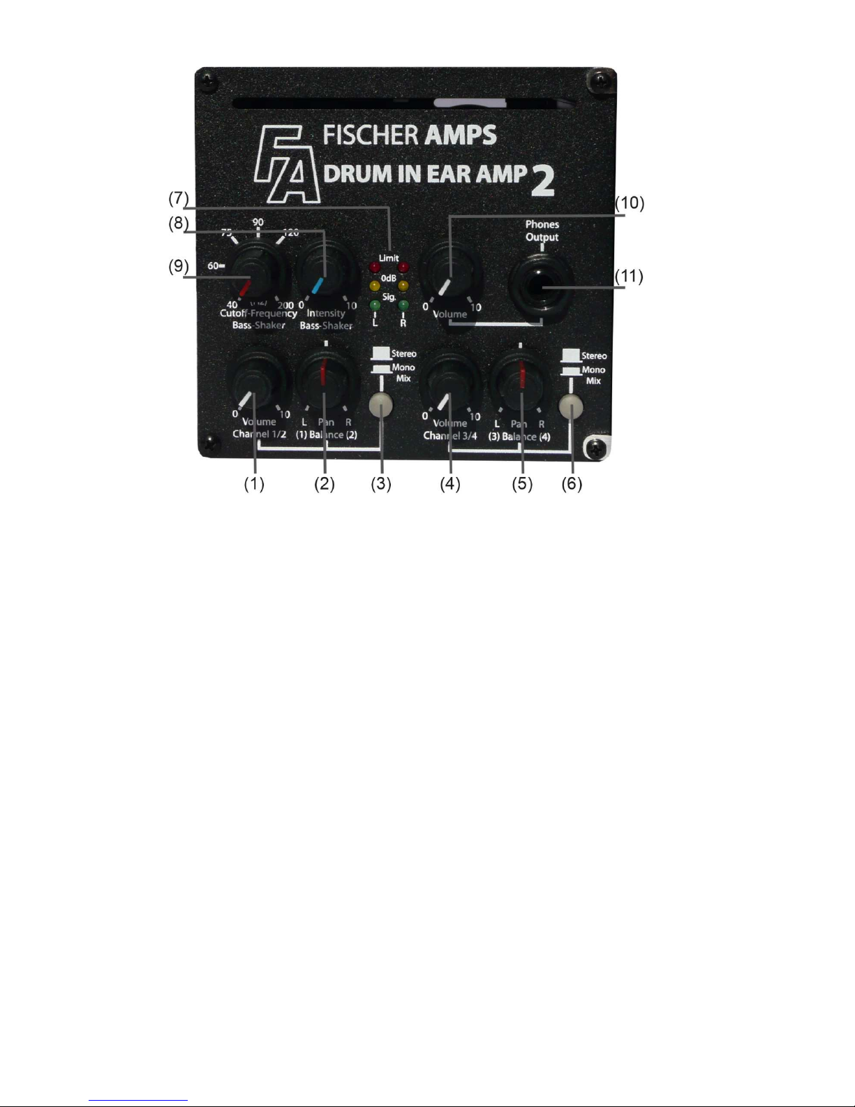
Controls at the Front
Description of the Actuators (front side):
(1)
Channel 1/2
Volume control: Preset of volume for channel 1 and 2
(2)
Channel 1/2
Pan (Balance) Control
In stereo mode: Adjust balance of volume between channel 1 and 2
channel 1 (left), channel 2 (right)
In mono-mix mode: Adjust volume level ratio between channel 1 and channel 2. Channels 1
and 2 are output together to both headphones. In middle position, both
channel levels are equal; at left stop only channel 1, at right stop only
channel 2
(3)
Change-over switch channel 1 and 2
Stereo / Mono Mix
Stereo mode: The device outputs the signal fed into the left input (channel 1) to the left
headphone and the signal from the right (channel 2) to the right
headphone.
Mono Mix mode: Channel 1 and channel 2 are mixed and output to both headphones. By
means of the Pan (Balance) control, the ratio between both channels
can be adjusted.
(4)

3
Channel 3/4
Volume control: Presetting of volume for channel 3 and 4
(5)
Channel 3/4
Pan (balance) control
In stereo mode: Adjust balance of volume between channel 3 and 4
Channel 3 (left), channel 4 (right)
In mono mix mode: Adjust volume level ratio between channel 3 and channel 4. Channels 3
and 4 are output to both earphones. In middle position both channel
levels are equal.
Pan (balance) control: At left stop only channel 3, at right stop only channel 4
(6)
Change-over switch channel 3/4
Stereo / Mono Mix mode
Stereo mode: The device outputs the signal fed into the left input (channel 3) at the left
earphone and the signal from the right (channel 4) at the right earphone.
Mono Mix mode: Channel 3 and channel 4 are mixed and output to both earphones.
The ratio between both channels can be adjusted by means of the pan
(balance) control.
(7)
LEDs Limit L/R: There are signal LEDs for the left and for the right channel (green,
yellow and red for clip). The preset input level should be adjusted so
that the yellow LED lights when there are input signals. When the red
LED lights, the preset level should be reduced.
The LEDs indicate the level before the master volume controls for the
earphones output and the bass shaker.
(8)
Intensity Bass Shaker Controller to adjust the intensity of the bass shaker signal at the shaker
output.
(9)
Control
Cut-off Frequency
Bass-Shaker Adjustment of the cut-off frequency of the bass shaker signal (low path
12 dB/Oct.). The adjustment range is 40 Hz – 200 Hz.
(10)
Volume control
earphones output
Control to set the overall headphone volume left and right.
(11)
6.3mm (1/4“) stereo jack: Connection of the earphone system
(minimum impedance 12 ohms per
side).
Maximum output power 150 mW per channel
Tip = left signal, Ring = right signal, Sleeve = ground
IMPORTANT
:The stereo jack may only be operated with a stereo headphone set with stereo jack
connector. When using a mono jack connector, the right side of the amplifier is
permanently short-circuited and is overloaded.
4
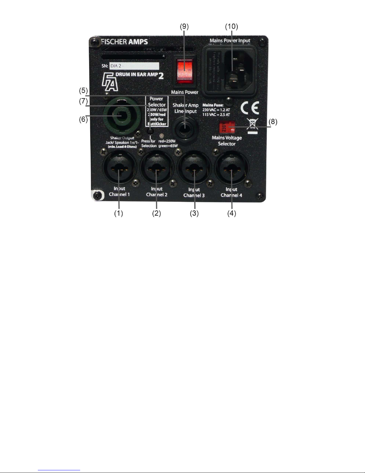
Actuators at the Back Side
Description of the actuators (back side):
(1 / 2)
Combined XLR/Jack Inputs
Channel 1 (left) Connections for the input signals from the mixing console.
Channel 2 (right) Assignment of the combined XLR/jack female connection:
1 = Ground = Sleeve
2 = Signal + = Tip
3 = Signal - = Ring
With unbalanced wiring, assign PIN 3 to ground (bridge in connection
plug). Nominal input level -10dBu, input impedance 10kohms
(3 / 4)
Combined XLR/Jack Inputs
Channel 3 (left) Connections for the input signals from the mixing console or another
Channel 4 (right) source (CD, drum computer, sequencer)
Assignment of the combined XLR/jack female connection:
1 = Ground = Sleeve
2 = Signal + = Tip
3 = Signal - = Ring
With unbalanced wiring, assign PIN 3 to ground (bridge in connection
plug). Nominal input level -10dBu, input impedance 10 kohms.
(5)
Line-In Shaker Amp Balanced jack input for direct control of the shaker section. The signal is
input before the active crossover. This feature is useful to actuate the
shaker via a separate aux-way of the monitor mixing console.
When using this input, input channels 1 to 4 are not routed to the shaker
section any more and thus are only present at the headphone section.

5
(6)
Shaker Output
Jack/Speakon 1+/1- Connection for the bass shaker or the ButtKicker LFE. Max. RMS output
power 65W with Low Power , and 250W in High Power mode; minimum
output impedance 4 ohms. In High Power mode, only use the Speakon
connection because of the strain on the plug-in system. The package
The package including the ButtKicker LFE comes with a suitable
Speakon cable.
(7)
Power Selector Switch Amplifier Switch over the amplifier to High Power / Low Power mode to operate
the bass shaker Bass Pump 3 (65 Watt) or the ButtKicker LFE (250 W).
The green LED lights in position Low Power, the red LED lights in
position High Power mode. The switch is pre-adjusted to the type of
bass shaker which is supplied in the package. Due to safety reasons,
switch-over is made by means of a pointed object.
(8)
Mains Voltage Selector: Adjustment of the mains voltage to the existing power grid 230 V AC or
115 V AC (50/60Hz).
The selector switch may only be activated when the power plug is
disconnected from the mains. The suitable mains fuse in the input
voltage socket has to be inserted: with 230V 1.25AT fuse, with 115V
insert the 2.5A fuse. Corresponding fuses are enclosed with the Drum In
Ear Amp 2.
(9)
Mains Power Switch: Switch on the voltage supply of the unit. When switched on, the Switch
lights red.
(10)
Mains Power Input: Euro mains socket with fuse holder to connect the mains cable.
Operating voltage 115/230VAC, 50/60Hz.
Caution: Connect a 3-pole cord with protective earth conductor (PE). Do not use any damaged
power cables.
Mounting the bass shaker to the drummer throne (for pictures see page 7):
•Unscrew the two butterfly nuts at the mount of the bass shaker.
•Fasten the bass shaker at the beam of the seat by means of the fastening clamp.
•Take care for a tight fit, as otherwise the vibrations cannot be transmitted optimally.
Mounting the amplifier to the Hi-hat machine or to the rack of the drum set:
•Attach the amplifier with the fastening clamp at an appropriate location.
•Slightly unscrew the butterfly nut to be able to fasten the amplifier.
•Fix the amplifier in an appropriate position with the butterfly nut.
•
Connect the bass shaker to the amplifier:
•Plug the 6.3 mm (1/4“) jack connector or the Speakon connector of the cable which is mounted to the
bass shaker into the Shaker Output socket at the amplifier (interlock Speakon plug after inserting by
turning it in the socket).

6
Connecting the power supply of the amplifier:
Connect the amplifier to an earthed safety socket with the cable supplied with the Drum In Ear Amp 2.
Connecting the input signals channel 1 to 4:
There are four inputs for the input signals. All inputs are balanced XLR / jack hybrid panel mount
connectors with a nominal input sensitivity of -10 dBu. So you can connect XLR plugs or balanced and
unbalanced jack connectors.
Reasonably, the monitor signal (monitor outputs of a mixing console) or the left/right sum signal are
connected to channel 1 and 2. In stereo mode, channel 1 is output left and channel 2 is output at the right.
If you only want to feed in a mono signal and would like to hear the signal on both earphone sides, press
key Mono for channel 1-2 at the front side of the amplifier.
At the inputs for channel 3 and 4, additional signals (such as CD players, sequencers, click signals, etc.)
are connected. If you only want to feed in a mono signal and would like to hear the signal on both
earphone sides, press key Mono for channel3-4 at the front side of the amplifier.
If you would like to hear the click signal at the right side only, plug it into channel 4. If you would like to hear
the click signal at the right side only, plug it into channel 3. You can also connect different signals to
channels 3 and 4 (e. g. sequencer and click). If you would like to hear these two signals at both earphone
sides, press key Mono for channel 3-4 at the front side of the amplifier. With the balance control of channel
3-4 the volume ratio of both signals can be adjusted. This is referred to as Mono-Mix Mode.
OPERATION OF THE DRUM IN EAR AMP 2:
Adjustment of the optimum working level:
When all required connections are made and the Drum In Ear Amp 2 is switched on, make sure that the
input signals have contact with the Drum In Ear Amp 2. Turn channel 1-2 volume control until the green
and yellow signal LEDs light. The red clip LED may only flash with short signal peaks, but should not light
steadily. Then you have the optimum working level. When you have also connected input signals to
channel 3-4, proceed as explained above, but use channel 3-4 volume control. When the yellow signal
LED does not light when the volume control is at the right stop (maximum), increase the level of the
connected input signal at the source device.
If the red clip LEDs light, decrease the level at the input controls of channel 1-2 or channel 3-4, as
otherwise the limiters respond, and the dynamic range is restricted.
Adjustment of the Earphone/Headphone Volume:
Connect your earphones to the phones output jack at the front. Any headphone system with an impedance
greater or equal 12 ohms can be connected at this jack. If your headphone system has a 1/8” stereo
connector, use the adapter supplied with the Drum In Ear Amp 2. Now adjust the volume which is
convenient for you with the volume control (Phones Out).
IMPORTANT: Use stereo headphone systems with 3-pole jack connectors.
Adjustment of the Intensity of the Bass Shaker:
Sit on the drummer seat and set the volume control of the bass shaker to an intensity which is convenient
for you compared to the earphone volume. The characteristics of the bass signal can be adjusted by
means of the cut-off frequency control of the bass shaker output. The more you turn the control in
clockwise direction, the more higher frequencies are output to the bass shaker (up to max. 200 Hz). The
adjustment you select can completely depend on your personal taste. Fischer Amps, however, recommend
a cut-off frequency of approx. 80 Hz.
7
WARRANTY:
The manufacturer grants a warranty of 24 months from the date of purchase by the original owner for defects in
materials or workmanship. When the appliance has been subject to misuse or has been altered, the warranty
expires. When returning the defective unit, enclose the receipt, pack the unit to avoid transit damage, and return
the unit carriage prepaid. The manufacturer does not accept carriage forward consignments.
Disposal of Old Electrical & Electronic Equipment
(Applicable in the European Union and other European countries with
separate collection systems)
This symbol on the product or on its packaging indicates that this product
shall not be treated as household waste. Instead it shall be handed over to
the applicable collection point for the recycling of electrical and electronic
equipment. By ensuring this product is disposed of correctly, you will help
prevent potential negative consequences for the environment and human
health, which could otherwise be caused by inappropriate waste handling
of this product.
The recycling of materials will help to conserve natural resources. For
more detailed information about recycling of this product, please contact
your local city office, your household waste disposal service or the shop
where you purchased the product.
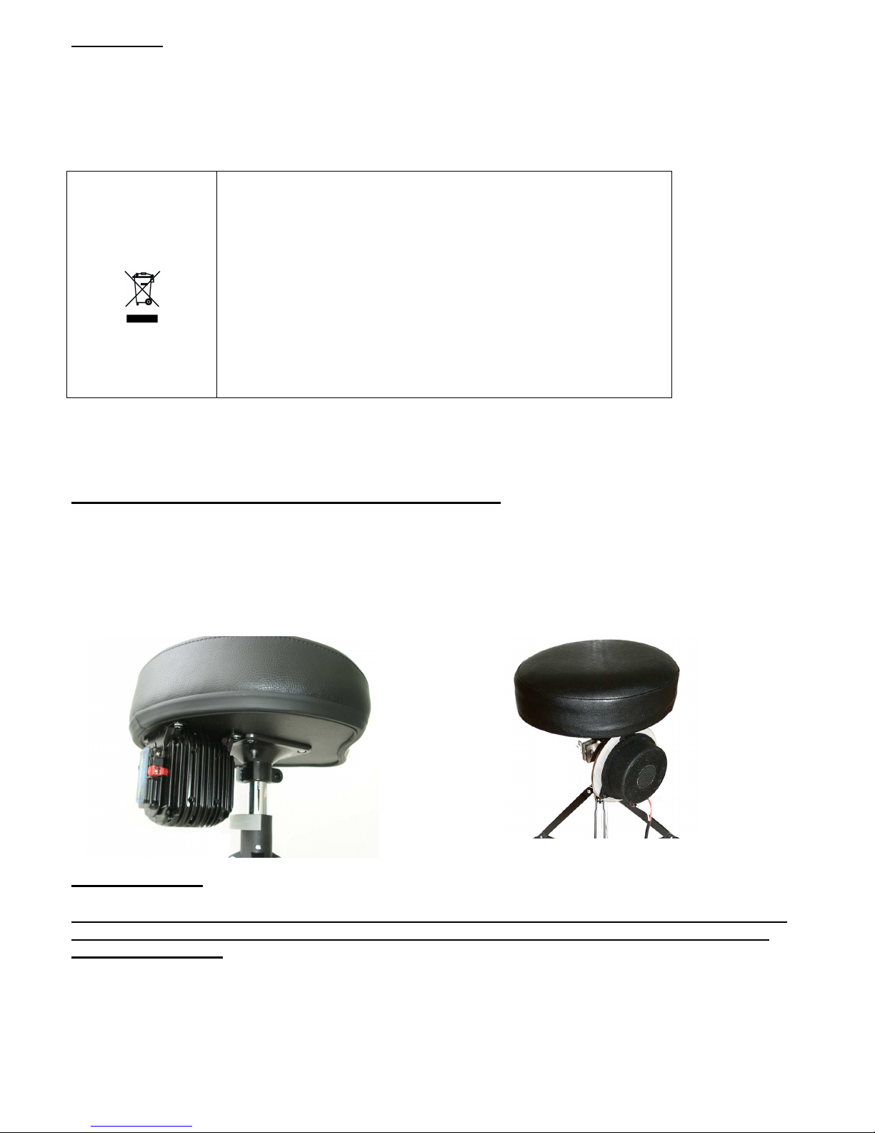
Attaching the Bass Shaker to the Drummer Seat
IMPORTANT:
Depending on the intensity of the bass shaker, the amplifier warms up to approx. 45 Centrigrades
during operation. However, this is normal, the housing is used as a heat sink for the dissipated
heat of the amplifier.
Direct assembly of the ButtKicker under the
seat (best intensity)
Assembly of the Bass Pump 3 with the
universal mount to the support of the
throne. The ButtKicker can also be
attached like this.

8
SPECIFICATIONS AMPLIFIER:
Dimensions L x W x H : 185 x 120 x 110 mm (7.3 x 4.7 x 4.3 inches)
Weight: 1.7 kg (3.75 lbs)
Input connectors: 4 Neutrik–XLR/jack combo female connector, 3-pole
Output connectors: Bass Shaker Out: 1 x Speakon/jack connector mono
Headphone Out: 1 x 6.3mm (1/4“) jack connector stereo
Frequency response: Headphones output 20 Hz – 20 kHz +/- 2dB
Bass shaker 20 Hz – 200 Hz (variable)
Min. Load impedance of the
Headphone system: 12 ohm per side
Input impedance channel 1-4: 10 kOhms
Max. input sensitivity balanced: + 10 dBu
channel 3-4: + 10 dBu
Max. output power connected to 16 Ohm
Headphone output: 150 mW per channel
Max. output power connected to 4 Ohm
Bass shaker amplifier: Low Level = 65W RMS
High Level = 250W RMS
Power supply: 230VAC 50/60 Hz
max. input power: approx. 280W
Power fuse: 1.25 AT with 230V mains voltage
2.5 AT with 115V mains voltage
SPECIFICATIONS BASS SHAKER:
Nominal impedance: 4 Ohm
Maximum power: 50 W RMS (Bass Pump 3)
400W RMS (ButtKicker LFE)
FISCHER AMPS
Hans-Ulrich-Breymann-Str. 3, DE-74706 Osterburken / Germany
Tel. +49 (0)6291–648 79-0, Fax 648 79-19
E-MAIL:
info@fischer-amps.de
, Internet:
www.fischer-amps.de
Other FISCHER Amplifier manuals


