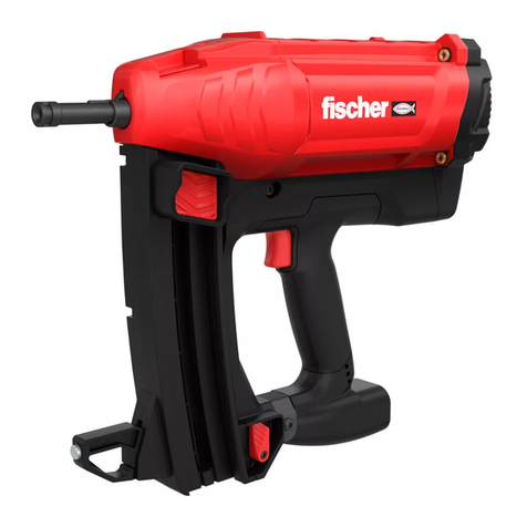
FISCHER Power Drive F35 User manual

EN
Operating Manual
Power Drive F35 Stud Driver

2
Masthead
Version: we_f35_en_11.2008
Copyright:
scherwerke GmbH & Co. KG
Weinhalde 14 - 18
Germany
72178 Waldachtal
Tel.: +49 744312-0
Fax: +49 744312-4222
E-mail: info@scher.de
Internet: www.scher.de
Passing on and duplication of this document,
exploitation and disclosure of its contents are
forbidden unless expressly approved. Viola-
tions render the oender liable to damages. All
rights reserved for the event of patent, utility
model or registered design applications.
This operating manual has been drawn up
with the greatest care. Nevertheless, scher-
werke GmbH & Co. KG assumes no liability for
possible errors in this operating manual and
their consequences. Furthermore, no liability is
assumed for direct or consequential damages
resulting from the improper use of the equip-
ment described.
The national safety and occupational safety
regulations and the safety precautions given in
this operating manual must be observed when
using the tool.
All product designations and brand names are
the property of their owners and are not explic-
itly marked as such.
Amendments to content reserved.

3
Table of Contents
1 About the Operating Manual 4
1.1 Symbols Used in this Operating Manual 4
2 Safety Precautions 5
2.1 Intended Use 5
2.2 Demands on the Operating Personnel 5
2.3 Personal Protective Equipment and Personal Safety 5
2.4 Improper Use 6
2.5 Working Environment 7
2.6 Handling of Cartridges 7
2.7 Transport and Storage 9
3 Description 10
3.1 General Product Description 10
3.2 Technical Data 10
3.3 Scope of Supply 11
3.4 The Functional Principle 12
3.5 Safety Devices 12
4 Before Starting Work 13
4.1 Analysis of the Base Material 13
4.2 Selection of Appropriate Cartridge 13
4.3 Selection of Appropriate Fastener Elements 13
4.4 Guidelines for Fastening 15
5 Operation 18
5.1 Handling 18
6 Service and Maintenance 22
6.1 Dismantling the Tool 22
6.2 Cleaning the Individual Parts 24
6.3 Assembling the Tool 25
6.4 Function Check 26
7 Troubleshooting 27
8 Consumables 35
8.1 Safety Cartridge Strips 35
8.2 Fastener elements 36
9 Overview of Spare Parts 38
10 Disposal 40
11 CIP Test Certication 40
12 Note for Germany 41
13 scher national subsidiaries 42

4
About the Operating Manual1
This operating manual contains all important information for safe use of the Power
Drive F35 Stud Driver. It also describes handling, maintenance, troubleshooting
and consumables.
Do not put the Stud Driver into operation before you have completely read and
˚
understood the operating manual.
Keep this operating manual with the Stud Driver at all times.
˚
The Power Drive F35 Stud Driver is also referred to as "tool" in this operating ˚
manual.
Symbols Used in this Operating Manual1.1
Observance of the safety and hazard warnings is a basic precondition for the safe
use of the Stud Driver. The dierent warnings are marked with corresponding
symbols.
DANGER!
This pictogram with the word "DANGER!" draws attention to an impending hazard that
will result directly in serious injury or even death if not avoided.
This arrow points to the measure(s) to be taken to avoid the impending hazard. ▸
WARNING!
This pictogram with the word "WARNING!" draws attention to an impending hazard that
may lead to serious injury or even death if not avoided.
This arrow points to the measure(s) to be taken to avoid the impending hazard. ▸
CAUTION!
This pictogram with the word "CAUTION!" draws attention to an impending hazard that
may result in minor to moderate injury or material damage if not avoided.
This arrow points to the measure(s) to be taken to avoid the impending hazard. ▸
NOTE
This pictogram "Note" draws attention to tips and recommendations for the eective
use and operation of the equipment.
In addition, the common pictograms and hazard symbols are used at the appropri-
ate points in this operating manual.

5
Safety Precautions2
Observance of the following safety precautions and the national safety and occupa-
tional safety regulations is a precondition for safe and trouble-free use of the Stud
Driver. Therefore read all the precautions carefully and observe them when working
with the equipment.
Intended Use2.1
The Power Drive F35 Stud Driver from scher is designed for the professional set-
tings of the intended fastener elements (see chapter 8) in suitable substrates (see
chapter 4).
DANGER!
If not used for the intended purpose the tool, the associated fastener elements and the
accessories available as options can pose a source of danger.
The safety precautions and the instructions on the care and maintenance of the Stud ▸
Driver in this operating manual must be observed at all times.
Demands on the Operating Personnel2.2
The minimum age for operation of the tool is stipulated in the national regula- ˚
tions.
The tool may only be operated manually and employed, serviced and maintained
˚
by professional, certied operators.
Carry out work with this tool in a concentrated, controlled and sensible manner
˚
at all times. Do not use the tool if you are tired or under the inuence of drugs,
alcohol or medication that can impair your balance and / or power of judgement.
Observe any physical and / or psychological limitations.
Do not eat, drink or smoke when working with the Stud Driver.
˚
During interruptions in work, remove the cartridge strips and fastener elements ˚
from the tool.
Never leave the tool lying around unsupervised.
˚
Personal Protective Equipment and Personal Safety2.3
Operators and other persons standing around must wear personal protective ˚
equipment at all times consisting of a helmet, goggles and ear protectors. If pro-
tective equipment is not worn, there is a danger of serious bodily injury as well
as injury to the eyes and hearing damage.
Always wear protective gloves when working with the tool, as the tool can
˚
become hot during operation.
During work, keep other persons - in particular children - out of the working area
˚
(see also notes in chapter 2.5).
Ensure that the handle of the equipment has a good grip and keep it clean, dry
˚
and free from oils and greases.

6
Before starting stud driving, ensure that there is no-one behind or under the ˚
place of work.
Never direct the tool towards yourself or other persons or press the tool against
˚
parts of the body. Serious or even fatal injuries can result even from uninten-
tional ring of the Stud Driver.
Improper Use2.4
The Stud Driver forms a technical unit together with the safety cartridges and ˚
fastener elements specied in chapter 8. For this reason only consumables, ac-
cessories and spare parts from scher designed for this tool may be used.
Mechanical modication or manipulation of the tool is not permitted. Do not
˚
manipulate or modify the tool.
On no account may the safety functions of the Stud Driver be by-passed.
˚
Always check the tool before starting work to ensure that it is functioning ˚
correctly. If the tool does not function correctly, it must be taken out of opera-
tion and clearly marked as defective. Do not use the tool again until it has been
properly repaired.
Always handle the tool as if it were ready for operation.
˚
Before starting work, check that the tool is unloaded and that the stud opening ˚
is free.
Carry out the driving operation only with fastener elements loaded, never with-
˚
out. Load the tool with fastener elements and cartridges only immediately before
starting work.
Ensure that only
˚ one single fastener element is inserted into the fastener guide
at a time.
Do not drive fastener elements into existing holes.
˚
Never press your nger against the trigger before the fastener element opening ˚
is pressed against the working surface.
Always hold the tool with bent arms perpendicularly to the working surface.
˚
If possible, use the stabilizer when driving studs into concrete or steel. ˚
Do not drive fastener elements into cast iron, aerated concrete, thin sheet metal ˚
(< 4 mm), ceramic tiles, hollow bricks, insulating materials, rock, copper, brass,
bronze, plastic, marble or glass. These materials can splinter.
If the tool is dropped, it must be inspected and repaired, if necessary, before
˚
work is continued. On no account may a damaged tool be used.
Safety Precautions2

7
Safety Precautions2
Working Environment2.5
The working area must be cordoned o and marked with warning signs when ˚
stud drivers are in use. The warning signs must bear the text "Stud drivers in
operation" and be set up a sucient distance from the area in which the tool is
being used.
Ensure at all times that the working area is clear on all sides.
˚
When using stud drivers, ensure that you have a stable working position and ˚
maintain your balance at all times. Avoid working on ladders.
Ensure that the working area is free from loose material and soiling at all times.
˚
Ensure good lighting in the working area and good ventilation in closed rooms.
The tool must
˚ not be employed in an explosive or inammable atmosphere.
Handling of Cartridges2.6
The cartridges to be used in the tool conform to hazardous goods class 1.4 S. ˚
The national regulations for the handling of the cartridges must be observed at
all times.
The cartridges may only be handled and used by certied personnel.
˚
Persons with poor eyesight, colour blindness or problems with reading must take ˚
special precautions in order to be able to distinguish between the cartridges of
the dierent power classes.
Do not exert force on the cartridges during loading and unloading of the tool.
˚
Always load the fastener element into the tool rst, then the cartridges. ˚
Always remove the cartridge from the tool rst before removing the fastener ˚
element.
Never try to lever a cartridge out of the chamber. This could lead to detonation of
˚
the cartridge.
Never leave unused cartridges lying around on working surfaces or on the oor.
˚
Keep the cartridges away from sources of heat and naked ames. ˚
Avoid bringing the cartridges into contact with acids, pickling solutions, oil and ˚
aromatic hydrocarbons.
Never throw the cartridges.
˚
Never try to open the cartridges. ˚
On no account may the cartridges be used in rearms. ˚
Never expose the cartridges to mechanical forces (e.g. blows) or heat. ˚
Hard objects must not strike or rub against the cartridges or their base. This ˚
could lead to detonation of the cartridges.
Cartridges must not be sent by post, packet or courier service.
˚
Cartridges must not be transported by public transport. ˚

8
Safety Precautions2
If the cartridge does not re
If a cartridge does not re, proceed as follows: ˚
If the cartridge does not re, press the fastener element opening rmly 1.
against the working surface for 30 seconds.
If the cartridge has still not red after this time, release the trigger and relieve 2.
the pressure on the tool while still hold the fastener element opening against
the working surface. Lift the tool o the working surface, ensuring that it is
not pointed towards yourself or other persons.
Pull the cartridge strip up by one cartridge, thus bringing a new cartridge into 3.
ring position. Use the remaining charges of the cartridge strip. Then dispose
of the strip in such a way that it cannot be used again.
If the charges do not re several times in succession or the fastener elements
˚
show signicantly reduced penetration depths, proceed as follows:
Stop work immediately.1.
Remove the cartridge strip and fastener element from the tool.2.
Dismantle the tool (see chapter 6.1).3.
Inspect the piston body and piston guide for wear and replace, if necessary.4.
Clean the tool (see chapter 6.2) and reassemble again (see chapter 6.3).5.
If the problem continues to exist, stop work with the tool immediately. Mark 6.
the tool clearly as "DEFECTIVE - DO NOT USE" and store in a locked container.
Contact your contract partner (see page 42).

9
Safety Precautions2
Transport and Storage2.7
NOTE
The cartridges to be used in the tool conform to hazardous goods class 1.4 S. The
national regulations for the transport and storage of the cartridges must be observed
at all times.
Never store, transport and hand over the Stud Driver in loaded condition and with a
fastener element inserted.
Transport
During transport, hard objects must not strike or rub against the cartridges or ˚
their base. This could lead to detonation of the cartridge.
Storage
Always store the ˚ unloaded Stud Driver and the cartridges in locked containers
separately from one another.
Store the Stud Driver in a dry and locked location. The location must be secured
˚
against unauthorised access.
The ambient and storage temperature must not be below -20 °C or above +35 °C
˚
for prolonged periods.

10
Description3
General Product Description3.1
The Power Drive F35 Stud Driver is a safe tool that can be employed for a wide
range of applications by professional, certied users.
The tool is intended for commercial use for xing purposes by driving elements of
the scher accessories product range developed specially for this eld of applica-
tion into concrete, steel, solid brick and solid lime-sand brick.
Only scher safety cartridges FSC 6.8 /11 (0.27 inch) may be used to generate the
propulsion gas. Fastening is performed directly through the part to be xed into the
anchoring substrate (base material). Predrilling of holes is not necessary.
The Stud Driver has a 6-position power regulator that allows the tool power to be
optimally adapted to the intended application.
The low noise and minimum recoil increase the comfort for the operator and thus
contribute signicantly to higher productivity. The powder-driven system is com-
pletely portable so that it can be used even in conned spaces and at points with
restricted access.
6
5
4
3
2
1
Rubber sheath1
Cartridge guide2
6-position power regulator3
Trigger4
Holding area for the loading process5
Fastener guide6
Technical Data3.2
Manufacturer scherwerke GmbH & Co. KG
Designation Power Drive F35 Stud Driver
Weight 2.35 kg
Tool length (maximum) 340 mm
Maximum length of the fastener element 62 mm (prenailing is necessary with longer elements)
Recommended maximum driving frequency 500 fastener elements / hour
Cartridges FSC GR (6.8 /11 mm), green
FSC YE (6.8 /11 mm), yellow
FSC RE (6.8 /11 mm), red
Power control 3 cartridge strengths
6-step power control by means of regulation knob

11
Description3
Scope of Supply3.3
After unpacking, check the contents of the package. The following parts belong to
the scope of supply of the tool:
1
11
910
8
2
3
4
5
6
7
12
Power Drive F35 Stud Driver1
Goggles2
Stabilizer3
Allen key4
Ear protectors5
Steel balls (spare parts)6
Clips (spare parts)7
Round brush, large8
Round brush, medium9
Round brush, small10
Wire brush11
Operating manual12

12
Description3
The Functional Principle3.4
The tool functions on the basis of the piston principle. This technique ensures opti-
mum working safety and reliable xing solutions. In view of its design, the tool is a
Class A Stud Driver in accordance with the German Firearms Act.
The Power Drive F35 Stud Driver operates on the indirect action principle. The ring
of the cartridge creates a positive pressure in the combustion chamber. The posi-
tive pressure acts on the contained piston and is transformed into motion energy
(kinetic energy). The piston transmits this kinetic energy directly to the fastener
element (stud) inserted into the fastener guide, thus permitting a controlled penetra-
tion into the base material.
This principle allows the velocity of the fastener element (stud) to be reduced to less
than 100 m/s, thus giving the system a very high degree of safety.
There is no risk of ricochets, as the piston is contained in the Stud Driver and the
driven fastener element (stud) is thus prevented from becoming a projectile.
During reloading of the Stud Driver, the piston is moved back to its starting position
(loading process). The cartridge strip is advanced at the same time. This enables
quick, inexpensive and safe working for the operator.
Safety Devices3.5
Drop protection
A possible ignition of the ring charge is prevented mechanically if the Stud Driver
collides with a hard surface.
Contact protection
The Stud Driver must be pressed with the fastener element opening completely
against the substrate before a stud can be driven.
Trigger protection
Simply pressing the trigger does not ignite the ring charge.
Firing protection
If the Stud Driver is pressed with the fastener element opening completely against
the substrate with the trigger already pressed, the ring charge is not ignited.

13
Before Starting Work4
Before working with the Stud Driver, it is essential that you familiarise yourself with
the characteristics of the base material and of the fastener elements. The materials
into which the fastener elements are to be driven must be analysed. The fastener
elements, the cartridge and the setting of the 6-position power regulator are then
selected on the basis of this analysis.
Analysis of the Base Material4.1
For the work with the Stud Driver it is necessary to determine the characteristics
of the base material into which the fastener element is to be driven by means of a
penetration test.
Try to drive the fastener element into the base material using a hammer. The
˚
base material is
too soft – if the fastener element penetrates easily into the base material,
too hard – if the fastener element becomes blunt,
too brittle – if it breaks or cracks,
suitable – if the fastener element remains sharp and leaves a deformation in the
base material.
Selection of Appropriate Cartridge4.2
The cartridges are distinguished according to their power classes and are corre-
spondingly colour coded (see chapter 8.1).
Always test a fastener element rst with cartridges of the lowest power class when
working with a new base material. If the fastener element does not achieve the
necessary penetration depth, try with the next higher power class until the required
penetration depth is reached.
Selection of Appropriate Fastener Elements4.3
Fixing in concrete
Eective anchoring depth (hef)
For xtures in concrete, the eective anchoring depth (hef) is the determining factor
for the selection of the appropriate fastener element. The eective anchoring depth
(hef) is dependent on the compressive strength of the concrete.
Compressive strength of concrete Eective anchoring depth (hef)
C16/20 30 - 35 mm *
C20/25 25 - 30 mm *
C30/37 20 - 25 mm *
The values shown are indicative values. Several test xings should be carried out in the base material to determine the exact values *
for the installation situation.

14
Before Starting Work4
Correct shaft length of the fastener element
The correct shaft length (L) is determined by the thickness of the part to be xed
(tx) and the eective anchoring depth (hef) using the following formula:
h
ef
t
fix
L = tx + hef
For xtures with stud bolts, the necessary shaft length corresponds to the eective
anchoring depth (hef), the thickness of the part to be xed (tx) does not have to be
taken into consideration.
Fixing in steel
Eective anchoring depth (hef)
For xtures in steel, the eective anchoring depth (hef) is the determining factor for
the selection of the appropriate fastener element. The eective anchoring depth (hef)
is dependent on the tensile strength of the steel.
Tensile strength of the steel (fuk) Eective anchoring depth (hef)
360 N/mm² 12 mm
510 N/mm² 10 mm
The values shown are indicative values. Several test xings should be carried out in the base material to determine the exact values *
for the installation situation.
Correct shaft length of the fastener element
The correct shaft length (L) is determined by the thickness of the part to be xed
(tx) and the eective anchoring depth (hef). If proper penetration of the base mate-
rial is desired, an allowance of 6 mm must be made (see following formulae).
Correct shaft length without penetration of the base material:
L = tx + hef
Correct shaft length with proper penetration of the base material:
L = tx + hef + 6 mm
For xtures with stud bolts, the necessary shaft length corresponds to the eective
anchoring depth (hef) plus 6 mm allowance, the thickness of the part to be xed (tx)
does not have to be taken into consideration.
L = hef + 6 mm
+ 6 mm
h
ef
t
fix

15
Before Starting Work4
Guidelines for Fastening4.4
The guidelines described below must be observed for xtures in dierent base
materials.
General
Do not drive fastener elements into cast iron, aerated concrete, thin sheet metal ˚
(< 4 mm), ceramic tiles, hollow bricks, insulating materials, rock, copper, brass,
bronze, plastic, marble or glass. These materials can splinter.
Do not drive fastener elements into thin or easily penetrated material that is not
˚
backed by concrete, solid brick or steel (xing of plasterboard or insulating pan-
els). If the base material is completely covered and therefore not visible, ensure
for safety reasons that there is a suitable base material before driving each stud
(see chapter 4.1).
DANGER!
Openings and recesses in the base material that are covered by parts to be xed and
that are therefore invisible to the operator pose a particular risk.
Check the base materials by means of a penetration test (see chapter 4.1) before ▸
driving each stud.
Concrete
The following guidelines apply for the installation of fastener elements in concrete.
Minimum base material thickness (hmin)
h
min
= 100 mm
The minimum thickness (hmin) of con-
crete base material must be 100 mm.
Minimum distance from edge (cmin)
c
min
= 100 mm
The minimum distance from the edge
(cmin) must be 100 mm.
If a smaller distance is necessary, carry
out a test xing rst, as the edge may
break away.

16
Before Starting Work4
Minimum distance between centres (smin)
s
min
= 75 mm
The minimum distance between centres
(smin) of the fastener elements must be
75 mm.
If a smaller distance is necessary,
carry out a test xing rst, as the area
between the fastener elements may
break away.
Hollow prestressed concrete plate ceilings
When installing fastener elements
in hollow prestressed concrete plate
ceilings, drive in the fastener elements
between the chambers to achieve maxi-
mum xing strength.
Steel
The following guidelines apply for the installation of fastener elements in structural
steel, whereby the tip penetrates completely through the structural steel part.
For the installation of fastener elements in high-strength structural steel, or for ap-
plications where the tip does not penetrate through the structural steel part or the
structural steel part is thicker than 10 mm, we recommend that a penetration test is
carried out (see chapter 4.1).
Minimum base material thickness (hmin)
h
min
= 4 mm
The minimum thickness (hmin) of steel
base material must be 4 mm.
Minimum distance from edge (cmin)
c
min
= 15 mm
The minimum distance from the edge
(cmin) must be 15 mm.
Minimum distance between centres (smin)
s
min
= 20 mm
The minimum distance between centres
(smin) of the fastener elements must be
20 mm.

17
Before Starting Work4
Distance from weld seams
min. 50 mm
The minimum distance from weld
seams must be 50 mm.
Distance from holes
min. 15 mm
The minimum distance from holes in the
base material must be 15 mm.
Masonry
For installation in masonry, the fastener
element must always be driven into
the brick (solid brick). The minimum
distances indicated in this chapter for
concrete must be observed.
Fixtures in masonry joints are not
permitted.

18
Operation5
Handling5.1
DANGER!
If not used for the intended purpose the tool, the associated anchoring and fastener
elements and the accessories available as options can pose a considerable source of
danger for the operator and other persons in the vicinity.
Before using the Stud Driver, be sure to read the safety precautions described in ▸
chapter 2 and observe these at all times.
Before putting the tool into operation, ensure that it is completely empty and that
˚
there is neither a cartridge nor a fastener element in the Stud Driver.
Check the tool for proper function and operability, see function check in chapter
˚
6.4.
Never put the tool into operation if it is not in proper working order, if you have
˚
any doubts about the proper function or if parts of the tool are damaged. Dam-
aged parts must be replaced immediately. In such cases, please contact your
contract partner.
Preparing the tool for stud driving
Do ˚ not direct the tool towards yourself or other persons in the vicinity.
DANGER!
In the event of an unintentional ring, the piston or the fastener element can be driven
through your hand or other parts of the body that may be in front of the fastener ele-
ment opening.
Never place your ngers or the whole hand in front of the fastener element opening. ▸
Always point the tool away from yourself and other persons.
Remove any cartridges from the tool.
˚
Insert the fastener element
Hold the tool with the fastener ele- ˚
ment opening facing upwards.
Insert the fastener element head-rst
˚
completely into the fastener guide.

19
NOTE
It should be possible to insert the fastener element without force. If it should be dicult
to insert the element, check the compatibility of the fastener element with the tool and
the condition of the guide disc on the fastener element. If necessary, use a dierent
fastener element.
Reloading of the tool
CAUTION!
Incorrect handling may result in crushing or burning of the hands.
Hold the cylinder only around the front outside end as shown. Always wear protec- ▸
tive gloves when working with the tool. On no account reach behind the cone.
Pull the cylinder at the front end ˚
out of the guide up to the stop as
illustrated, then push it in again
completely. This operation moves the
piston back to its starting position
and the cartridge is advanced.
Insert cartridge strip
Load a new cartridge strip always after the reloading process. If the cartridge strip
is inserted before the fastener element is loaded or before the reloading process,
the rst cartridge will not re.
Insert the cartridge strip into the ˚
cartridge guide in the handle from
below as illustrated.
Push the cartridge strip into the
˚
guide until the lower end is ush
with the underside of the handle.
Inserting a partially used cartridge
strip:
Insert the cartridge strip from below ˚
and pull out from above until the
rst functional cartridge is in ring
position.
DANGER!
The tool is now ready for operation. The safety device in the tool is released if the Stud
Driver is pressed against an object. Observe the safety precautions in chapter 2.
Never direct the loaded tool towards any part of your body or towards another per- ▸
son. Handle the loaded tool with the greatest care!
Operation5

20
Operation5
Setting the power regulator
The force acting on the fastener element can be adjusted by turning the 6-position
power regulator on the right-hand side of the housing.
Position 1 = Lowest force
Position 6 = Highest force
Check the setting of the 6-position ˚
power regulator and adapt it to your
intended application, if necessary.
Stud driving
Ensure that you have a stable work- ˚
ing position.
Wear protective gloves when work-
˚
ing with the tool.
Hold the tool perpendicularly to the
˚
substrate into which the fastener
element is to be driven.
Press the tool rmly against the ˚
substrate with bent arms until the
fastener guide is completely pushed
in.
Press the trigger.
˚
Retract the tool from the substrate ˚
immediately after driving the stud to
prevent overheating.
DANGER!
Inappropriate handling while trying to unload a jammed or defective Stud Driver may
result in a cartridge ring.
Always point the tool away from yourself and other persons when unloading. ▸
Prepare the tool for driving the next stud by inserting a new fastener element
˚
and reloading the tool.
The cartridge strip is advanced during the reloading process.
˚
Remove the cartridge strip when all the cartridges have been red. ˚
Table of contents
Other FISCHER Power Tools manuals
Popular Power Tools manuals by other brands
Makita
Makita KP0810CJ instruction manual
Weller
Weller WLIR30 Translation of the original instructions

Ryobi
Ryobi ERT1400RV user manual
HSS Hire
HSS Hire 47416 Operating & safety guide
Pittsburgh
Pittsburgh Pittsburgh Automotive Portable Tire Changer Owner's manual & safety instructions

Sears
Sears Companion 919.19007 General manual

