Fisher & Paykel WD7560P1 User manual

Installation Instructions
Please read and follow the ‘Safety and warnings’ and ‘Installation instructions’ sections carefully before using
your washer dryer!
Accessories
Please check you received the following accessories with your Fisher & Paykel washer dryer. You will find them inside
the drum:
• 1 x Inlet hose
• 1 x Drain hose guide
• 1 x Installation instructions and user guide
• 1 x Spanner
• 1 x Installation leaflet (attached to the top of the washer)
• 1 x Hose clamp (WD8060P1 model only)
Unpacking
To ensure the best performance from your new washer dryer please follow the instructions below.
Removing The Packaging
1. Remove the outer packaging (including the polystyrene packer and plastic wrapping). All packaging must be
removed prior to use. Ensure these materials are kept out of reach of children.
https://producthelp.fisherpaykel.com/au/Wash/Front_Loaders/Washer_Dryer_Combo/WD8560F1/User_Guide_WD8560F1/03…
Updated: Sat, 15 Feb 2020 18:52:05 GMT
Powered by
1

Asmall amount of water may be seen inside the packaging and inside the washer dryer. This is the
result of factory testing and is normal.
2. Tilt the product backwards and ‘walk’ it off the base one foot at a time. Not doing so may cause damage to your
floor and washer dryer.
3. Remove all packaging and accessories from inside the drum.
Removing The Transit Bolts
The clothes washer dryer is fitted with 4 transit bolts at the rear to prevent internal damage during transportation.
• The 4 transit bolts MUST be removed prior to operation of the machine. Failure to remove these
will result in damage to the product.
• Ensure packaging materials are kept out of reach of children.
• Please help protect the environment and dispose of the packaging from around the washer dryer
in an environmentally friendly manner.
To Remove The Bolts:
1. Use a spanner or socket to unscrew and remove all four transit bolts at the back of the washer dryer (A).
2. Pull the black rubber grommets to remove the bolt, grommet and white plastic spacers from the machine. Keep
the transit bolts in case they are required for future transit of the machine. Never transport the machine
without the transit bolts properly fixed in place.
3. Cover the bolt holes with the white plastic plugs which are attached to the machine and located near each hole
(B). Push to clip into place.
https://producthelp.fisherpaykel.com/au/Wash/Front_Loaders/Washer_Dryer_Combo/WD8560F1/User_Guide_WD8560F1/03…
Updated: Sat, 15 Feb 2020 18:52:05 GMT
Powered by
2

Removing the transit safety bolts
Installation Location
• The washer dryer must be installed in a well-ventilated, dust-free environment.
• The washer dryer must not be installed on any textured floor coverings (eg carpet, rugs) to
ensure that openings at the base of the machine are not obstructed.
• Do not install the washer dryer behind a lockable door, sliding door, or behind a door where the
hinge is on the opposite side to that of the washer dryer in such a way that the full opening of the
door is inhibited. Ensure the washer dryer door can always be opened fully.
This washer dryer CANNOT BE INVERTED AND MOUNTED ON THE WALL.
Product Dimensions
https://producthelp.fisherpaykel.com/au/Wash/Front_Loaders/Washer_Dryer_Combo/WD8560F1/User_Guide_WD8560F1/03…
Updated: Sat, 15 Feb 2020 18:52:05 GMT
Powered by
3

FRONT VIEW
TOP VIEW
Product Dimensions WD7560P1
(mm)
WD8060P1
(mm)
WD8560F1
(mm)
Overall height of product 850 850 850
B Overall width of product 600 600 600
C Overall depth of product (including dial and door
when closed) 590 590 645
D Depth with door open 1010 1010 1065
E Minimum door clearance to adjacent wall 330 330 330
Standpipe height min.
800 – 1200
min.
800 – 1200
min.
800 – 1200
https://producthelp.fisherpaykel.com/au/Wash/Front_Loaders/Washer_Dryer_Combo/WD8560F1/User_Guide_WD8560F1/03…
Updated: Sat, 15 Feb 2020 18:52:05 GMT
Powered by
4

Product Dimensions WD7560P1
(mm)
WD8060P1
(mm)
WD8560F1
(mm)
Maximum Capacity kg kg kg
Wash capacity 7.5 7.0 8.5
Dry capacity 4.0 4.0 5.0
The exact height of your washer dryer is dependent on how far the feet are extended from the base
of the machine. The space where you install your washer dryer needs to be at least 40mm wider and
20mm deeper than its dimensions.
This machine must not be installed and operated on a plinth.
Levelling The Machine
It is IMPORTANT to level the machine to ensure good spin
performance, and to minimise noise, vibrations and wear and tear on
the washer dryer.
1. Before positioning the machine in its final position, check that
the machine is level, front to back and side to side.
2. Manoeuvre the product into its final position (we suggest a
minimum clearance of 20mm each side).
3. Use a spirit level to check that the machine is correctly level.
The washer dryer comes with four adjustable feet, wind all
four feet up or down until the dryer is correctly level. Place
the spirit level on top of your washer dryer in the following
places;
• left to right,
Levelling the feet
https://producthelp.fisherpaykel.com/au/Wash/Front_Loaders/Washer_Dryer_Combo/WD8560F1/User_Guide_WD8560F1/03…
Updated: Sat, 15 Feb 2020 18:52:05 GMT
Powered by
5

• back to front,
• corner to corner.
The machine is considered level when the bubble sits in the centre of
the two lines when placed flat on top of the machine.
4. Using the spanner provided, tighten the lock nuts against the
base of the machine to lock the feet in position.
Never unscrew the feet completely from their housings.
After levelling, the corners of the washer dryer cabinet should be clear
of the floor and the machine must not rock in any direction. Locking the feet
Connecting to The Water Supply
Inlet Hose
• A new hose is provided with the
washer dryer and should be used to
connect the washer dryer to the
water mains.
• Old hoses should not be re-used.
• We recommend that the inlet hose
be changed every 5 years.
Failure
to do so
may
result in
a flood
and
damage
to
property
Straight (tap) end Elbow (machine)
end
Inlet hose ends
1. Connect the straight end of the inlet hose to the cold tap and the elbow end to the machine inlet valve. Tighten
the inlet hose end by hand until the hose seal just makes contact with the tap sealing face and then tighten a
https://producthelp.fisherpaykel.com/au/Wash/Front_Loaders/Washer_Dryer_Combo/WD8560F1/User_Guide_WD8560F1/03…
Updated: Sat, 15 Feb 2020 18:52:05 GMT
Powered by
6

further half-turn. Make sure there are no kinks in the hose.
2. Turn the tap on and check for leaks. Check for leaks again after 24 hours.
The cold water temperature should not exceed 35°C.
Water Supply Requirements:
• Inlet water pressure: Maximum 1000kPa (150psi), Minimum 30kPa (4.5psi)
• Inlet water flow rate: Minimum 6 litres/minute
An internal heater in the product will heat the cold water to the selected cycle temperature.
Draining
Drain hose placement in a stand pipe or tub
1. To guide the drain hose over the tub or
standpipe the hose guide must be fitted to the
drain hose. The height of the standpipe or tub
should be between 800 – 1200mm.
2. Secure the hose guide so it cannot become
dislodged from the standpipe or tub.
https://producthelp.fisherpaykel.com/au/Wash/Front_Loaders/Washer_Dryer_Combo/WD8560F1/User_Guide_WD8560F1/03…
Updated: Sat, 15 Feb 2020 18:52:05 GMT
Powered by
7

• If the drain hose is placed
on the ground or if the
standpipe or tub is less
than 800mm high, the
machine will continuously
drain while being filled
(siphon).
• Regularly check that your
standpipe or tub is free
from lint or other
obstructions, which may
affect how your machine
works or may cause
flooding.
Attaching Drain Hose To Spigot
1. Guide drain hose through hose guide
2. Secure hose guide to back wall of cupboard
using a screw. The height of the drain hose
should be between 500 – 800mm from ground
level.
3. Attach drain hose to spigot and secure using a
hose clamp ensuring the blanking insert is
cleared from spigot.
4. Check for leaks.
• The drain hose should be checked from time to
time and replaced if any damage (eg wear, cuts,
bulges, kinks, leaks, etc) is found. Do not bend
the drain hose sharply, as this may cause it to
split.
• In multi-storey apartments or any upper floor, the
machine should be installed on a floor equipped
with a drain.
• Draining must comply with local by-laws.
Fitting the drain hose guide
Attaching drain hose to spigot
Electrical Connection
1. This appliance must be connected to a 220V – 240V, 50Hz, sinusoidal, minimum 10A electrical supply.
https://producthelp.fisherpaykel.com/au/Wash/Front_Loaders/Washer_Dryer_Combo/WD8560F1/User_Guide_WD8560F1/03…
Updated: Sat, 15 Feb 2020 18:52:05 GMT
Powered by
8

2. Uncoil the power cord, remove and discard the plastic pin cover and plug into a wall socket.
3. Connect the appliance to an earthed outlet protected by a fuse of suitable capacity.
• Check the power cord for damage and make sure it is not squashed or twisted when installing the washer.
• Always remove the power cord from a socket by the plug, not by the cord.
• If you are using an extension cord or a portable electrical outlet device (eg multi-socket outlet
box), ensure that it is positioned so that it does not come into contact with water or moisture.
FAILURE TO DO SO MAY RESULT IN DEATH OR ELECTRICAL SHOCK.
• Do not touch or operate the machine with wet hands or with bare-feet.
• A damaged power cord must be replaced by a Fisher & Paykel trained and supported service
technician, in order to avoid a hazard. The appliance must not be operated until it is repaired, as
there is a risk of electric shock.
• Do not operate this machine if it has been damaged during transport. Contact your Fisher &
Paykel dealer or Fisher & Paykel trained and supported service technician.
Spare Parts
Available from your Fisher & Paykel dealer or a Fisher & Paykel trained and supported service technician.
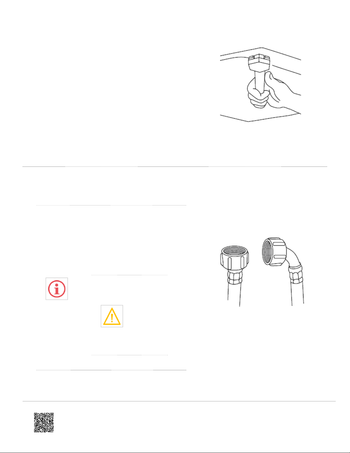
Hose Inlet Long (2m) Part No. 422680P
Hose Inlet Large Bore Part No. 426123P
Drain Hose Extension (not suitable for attaching to a spigot) Part No. 425627P
Completing The Installation
Installation Test Cycle
Do this before you wash or dry any items in your washer dryer. This is to check that your washer
dryer is installed and functioning correctly prior to use.
1. Turn your washer dryer on by pressing the ‘POWER’ button.
2. Select the ‘Quick Wash 30’ cycle. Ensure the drum is empty and the door closed.
https://producthelp.fisherpaykel.com/au/Wash/Front_Loaders/Washer_Dryer_Combo/WD8560F1/User_Guide_WD8560F1/03…
Updated: Sat, 15 Feb 2020 18:52:05 GMT
Powered by
9

3. Touch the
button. The machine will start to fill.
• Observe the machine for any problems (eg leaking from the hose, excess noise or vibrations).
• The washer will beep and display any faults on the screen if there are any problems. Refer to ‘Before you call
for Service’ section at the back of this book.
4. Wait until you see water in the bottom of the drum.
5. Touch
to stop the cycle, then press ‘POWER’ to turn the machine off.
6. Press ‘POWER’ again, select the ‘Spin’ cycle and touch
.
• Check the drain hose is firmly secured to the standpipe or tub, or spigot.
• Observe that the machine pumps out the water, and spins.
If there are any problems, you must address these before proceeding with normal use. The washer
dryer will automatically turn off at the end of the cycle if there are no problems.
https://producthelp.fisherpaykel.com/au/Wash/Front_Loaders/Washer_Dryer_Combo/WD8560F1/User_Guide_WD8560F1/03…
Updated: Sat, 15 Feb 2020 18:52:05 GMT
Powered by
10
This manual suits for next models
2
Table of contents
Other Fisher & Paykel Washer Dryer manuals

Fisher & Paykel
Fisher & Paykel 11 Series User manual

Fisher & Paykel
Fisher & Paykel WD8060P1 Operating instructions

Fisher & Paykel
Fisher & Paykel WD8560F1 Mounting instructions

Fisher & Paykel
Fisher & Paykel WD8060P1 User manual

Fisher & Paykel
Fisher & Paykel DE4024P2 User manual

Fisher & Paykel
Fisher & Paykel WD8560F1 Manual
Popular Washer Dryer manuals by other brands

Electrolux
Electrolux EWW1697MDW user manual

Whirlpool
Whirlpool WFC 3C26 manual

Midea
Midea MF100D80WB Series user manual

Tricity Bendix
Tricity Bendix CWD 1000 Operatng and installation instructions

Alliance Laundry Systems
Alliance Laundry Systems LTS84B*H operating instructions

GE
GE GUD27GESNWW installation instructions