Fisher-Rosemount Chempure Series User manual
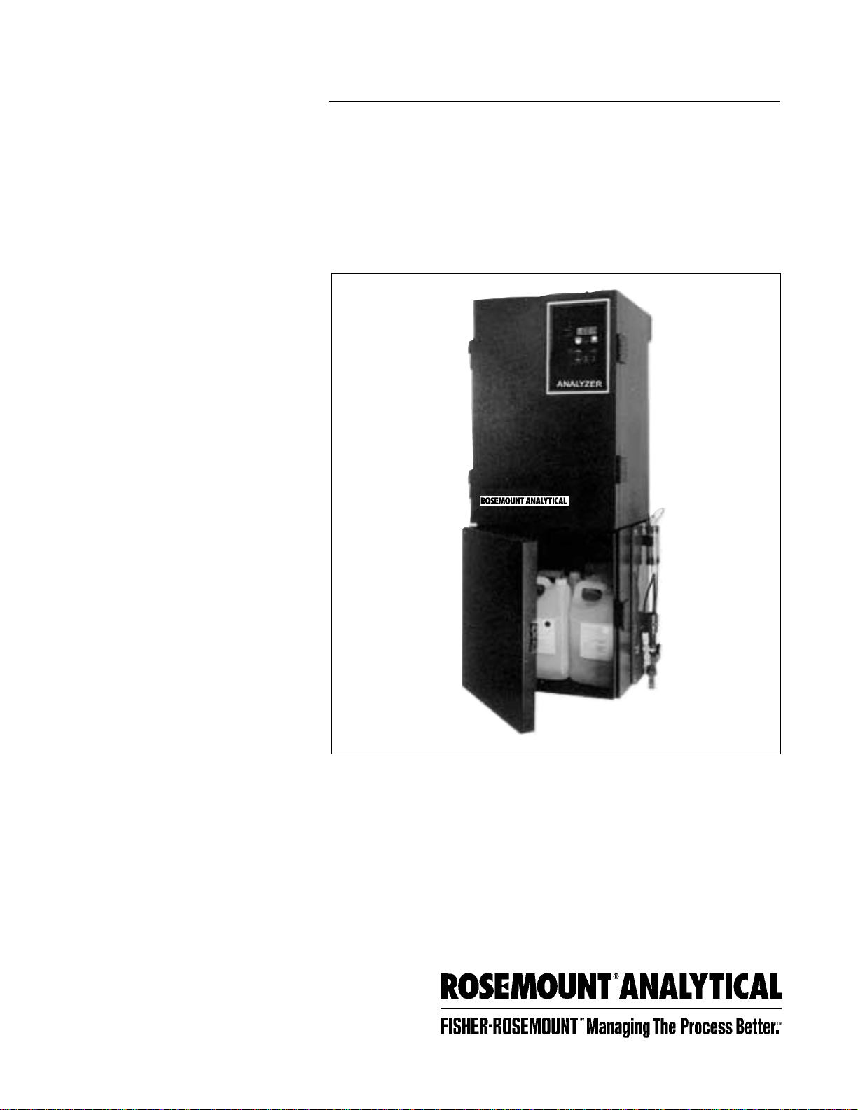
Chempure™ Series
Continuous Flow
Analyzers
Instruction Manual
P/N 51-Chemp
May 1997
Chempure
CAUTION
This product generates, uses and can radiate
radio frequency energy and thus can cause radio
communication interference. Improper installation,
or operation, may increase such interference. As
temporarily permitted by regulation, this unit has
not been tested for compliance within the limits of
Class A computing devices, pursuant to Subpart
J of Part 15, of FCC Rules, which are designed to
provide reasonable protection against such inter-
ference. Operation of this equipment in a residen-
tial area may cause interference, in which case
the user at his own expense, will be required to
take whatever measures may be required to cor-
rect the interference.
ESSENTIAL INSTRUCTIONS
READ THIS PAGE BEFORE PROCEEDING!
Your purchase from Rosemount Analytical, Inc. has result-
ed in one of the finest instruments available for your par-
ticular application. These instruments have been
designed, and tested to meet many national and interna-
tional standards. Experience indicates that its perform-
ance is directly related to the quality of th installation and
knowledge of the user in operating and maintaining the
instrument. to ensure their continued operation to the
design specifications, personnel should read this manual
thoroughly before proceeding with installation, commis-
sioning, operation, and maintenance of this instrument.
• Failure to follow the proper instructions may cause any
one of the following situations to occur: Loss of life; per-
sonal injury; property damage; damage to this instru-
ment; and warranty invalidation.
• Ensure that you have received the correct model and
options from your purchase order. Verify that this man-
ual covers your model and options. If not, call 1-800-
854-8257 or 714-863-1181 to request correct manual.
• For clarifications of instruments, contact your
Rosemount representative.
• Follow all warnings, cautions, and instructions marked
on and supplied with the product.
• Use only qualified personnel to install, operate, update,
program and maintain the product.
• Educate your personnel in the proper installation, oper-
ation, and maintenance of the product.
• Install equipment as specified in the Instruction section
of this manual. Follow appropriate local and national
codes. Only connect the product to electrical and pres-
sure sources specified in this manual.
• Use only factory documented components for repair.
Tampering or unauthorized substitution of parts and
procedures can affect the performance and cause
unsafe operation of you process.
• All equipment doors must be closed and protective
covers must be in place unless qualified personnel are
performing maintenance.
WARNINGS
ELECTRICAL SHOCK HAZARD!!
• Installation of cable connections and servicing of
this product require access to shock hazard volt-
age levels.
• Main power and relay contacts wired to separate
power sources must be disconnected before
servicing.
• Don not operate or energize instrument with
case open!
• Non-metallic cable strain relief do not provide
grounding between conduit connections! Use
grounding type bushings and jumper wires.
• Electrical installation must be in accordance with
the National Electrical Code (ANSI/NFPA-70)
and/or any other applicable national or local
codes.
• Operate only with front and rear panels fastened
and in place over terminal area.
• Safety and performance require that this instru-
ment be connected and properly grounded
through a three-wire power source.
• Proper relay use and configuration is the responsibility
of the user.
Rosemount Analytical Inc.
Uniloc Division
2400 Barranca Parkway
Irvine, CA 92606 USA
Tel: (949) 863-1181
http://www.RAuniloc.com

CHEMPURE MANUAL TABLE OF CONTENTS
SECTION TITLE.......................................................................................................................... PAGE
1 Introduction............................................................................................................... 1
2 Unpacking ................................................................................................................. 1
3 Instrument Description............................................................................................ 2
3.1 Analyzer Front View.................................................................................................... 2
3.1.1 Main Cabinet .............................................................................................................. 2
3.1.2 Reagent Cabinet ........................................................................................................ 2
3.2 Keypad Panel............................................................................................................. 4
3.2.1 Panel........................................................................................................................... 4
3.2.1 Keypad ....................................................................................................................... 4
3.3 Electronics Panel........................................................................................................ 5
3.3.1 Electronic Panel.......................................................................................................... 5
3.3.2 CPU Board..................................................................................................................6
3.3.3 Fault/Analog Board..................................................................................................... 6
3.4 Colorimeter................................................................................................................. 7
3.5 Pump and Reaction Vessel Assembly ..................................................................... 8
3.6 Back of Main Cabinet................................................................................................. 9
3.7 Input/Output Panel ..................................................................................................... 9
3.8 Computer Interface ................................................................................................... 10
3.9 Overflow Sampler Assembly...................................................................................... 11
4 Installation................................................................................................................. 12
4.1 Main Cabinet Mounting ............................................................................................. 12
4.1.1 General recommendations ........................................................................................ 12
4.2 Reagent Cabinet Mounting........................................................................................ 12
4.3 Waste Tube Installation............................................................................................... 12
4.4 Overflow Sampler Assembly...................................................................................... 13
4.5 Electrical Connections ............................................................................................... 13
4.6 Colorimeter ................................................................................................................ 15
4.7 Pump and Reaction Vessel Assembly ..................................................................... 15
4.8 Pump Tubing Harness................................................................................................ 16
4.9 Fluidics ....................................................................................................................... 17
4.10 Reagents ....................................................................................................................17
5 Using the Analyzer................................................................................................... 18
5.1 Operational Overview................................................................................................. 18
5.2 Keypad Lock.............................................................................................................. 18
5.3 Entering Numeric Values............................................................................................ 18
5.4 Specific Analyzer Chemistry...................................................................................... 18
6 Start-Up ..................................................................................................................... 19
6.1 Overflow Sampler Assembly...................................................................................... 19
6.2 Fluidics........................................................................................................................ 19
6.3 Reagents .................................................................................................................... 19
6.4 Power.......................................................................................................................... 19
6.5 Pump........................................................................................................................... 19
6.6 Heating Bath............................................................................................................... 19
i
Chempure™
TABLE OF CONTENTS

ii
CHEMPURE MANUAL TABLE OF CONTENTS
SECTION TITLE.......................................................................................................................... PAGE
7 Calibration and Operation....................................................................................... 20
7.1 Auto Calibration.......................................................................................................... 20
7.2 Manual Baseline Correction....................................................................................... 20
7.3 Manual Fullscale Calibration...................................................................................... 20
7.4 Sample Analysis......................................................................................................... 20
8 Shutdown .................................................................................................................. 21
8.1 Overnight Shutdown................................................................................................... 21
8.2 Shutdown for a Few Days or More............................................................................. 21
8.3 After Overnight Shutdown.......................................................................................... 21
8.4 After Shutdown For a Few Days or More................................................................... 21
8.5 If Shutdown With Reagents in Tubing........................................................................ 21
9 Accessories............................................................................................................... 22
9.1 Chart Recorder........................................................................................................... 22
9.1.1 Span Adjustment........................................................................................................ 22
9.1.2 Multi-Stream Analysis................................................................................................. 23
9.2 Alarms......................................................................................................................... 23
9.3 Multi-Stream Analysis................................................................................................. 24
9.3.1 Installation................................................................................................................... 24
9.3.1.1 Multi-Stream Circuit Board......................................................................................... 24
9.3.1.2 Keypad Panel and Display Board Assembly............................................................ 24
9.3.2 Multi-Stream Solenoid Valves..................................................................................... 25
9.3.2.1 Overflow Sampler Assembly...................................................................................... 25
9.3.3 Set-Up......................................................................................................................... 25
9.3.4 Sample Analysis......................................................................................................... 26
9.3.4.1 Automatic Multi-Stream Analysis............................................................................... 26
9.3.4.2 Manual Multi-Stream Analysis.................................................................................... 26
9.4 IF-100 In-Line Filter..................................................................................................... 26
9.5 Computer Interface .................................................................................................... 26
9.5.1 Normal Data Output Format....................................................................................... 26
9.5.2 Data Configuration ..................................................................................................... 27
9.5.3 RS232-C Pin Configuration........................................................................................ 27
9.5.4 RS232-C Start-Up....................................................................................................... 27
9.5.5 RS232-C Function Commands.................................................................................. 27
9.6 Printer Interface.......................................................................................................... 28
9.6.1 Pin Configuration........................................................................................................ 28
9.7 Printer Operation ........................................................................................................ 28
9.7.1 Setting Printer Internal Clock...................................................................................... 28
9.7.2 Single Stream Operation............................................................................................ 29
9.7.3 Multistream Operation................................................................................................ 29
9.8 Relay Output Option................................................................................................... 29
9.8.1 Relay Output Contact Rating..................................................................................... 29
9.8.2 Relay Output Option (Multistream)............................................................................ 29
TABLE OF CONTENTS (CON’T)

iii
CHEMPURE MANUAL TABLE OF CONTENTS
SECTION TITLE.......................................................................................................................... PAGE
10 Preventive Maintenance.......................................................................................... 30
10.1 Maintenance Schedule.............................................................................................. 30
10.1.1 Weekly ........................................................................................................................ 30
10.1.2 Monthly ....................................................................................................................... 30
10.1.3 Quarterly..................................................................................................................... 30
10.1.4 Yearly .......................................................................................................................... 30
10.2 Maintenance Procedures........................................................................................... 30
10.2.1 NaOH Fluidics Wash (Silica Only) ............................................................................. 30
10.2.2 Pump Tubing Harness Replacement......................................................................... 30
10.2.3 Colorimeter Source Lamp Inspection........................................................................ 31
10.2.4 Interference Filter Cleaning........................................................................................ 31
10.2.5 Sample Intake Tubing Replacement ......................................................................... 31
11 Troubleshooting........................................................................................................ 32
11.1.1 Symptom Chart........................................................................................................... 32
11.1.2 Test Functions............................................................................................................. 33
12 Repair and Service................................................................................................... 34
12.1 Colorimeter.................................................................................................................34
12.1.1 Source Lamp Replacement....................................................................................... 34
12.1.2 Interference Filter Replacement................................................................................. 34
12.1.3 Sample Flow Cell Replacement................................................................................. 34
12.2 Pump and Reaction Vessel Assembly....................................................................... 35
12.2.1 Pump Tubing Harness Replacement......................................................................... 35
12.2.2 Reaction Vessel Replacement................................................................................... 37
12.3 Circuit Boards............................................................................................................. 37
12.4 Fuses .......................................................................................................................... 37
13 Appendix ................................................................................................................... 38
Wiring Diagram........................................................................................................... 38
Help Sheet.................................................................................................................. 39
Specific Chemistries................................................................................................... 41
14 Ordering Information................................................................................................ 43
14.1 Reagents ....................................................................................................................43
14.2 Replacement Parts and Accessories........................................................................ 43
15 Specifications ........................................................................................................... 44
TABLE OF CONTENTS (CON’T)

iv
CHEMPURE MANUAL TABLE OF CONTENTS
LIST OF FIGURES
FIGURE TITLE.......................................................................................................................... PAGE
3-1 Analyzer Front View.................................................................................................... 3
3-2 Keypad Panel............................................................................................................. 4
3-3 Electronics Panel........................................................................................................ 5
3-4 CPU Board.................................................................................................................. 6
3-5 Fault/Analog Board..................................................................................................... 6
3-6 Colorimeter Assembly................................................................................................ 7
3-7 Pump Assembly Components................................................................................... 8
3-8 Back of Analyzer ........................................................................................................ 9
3-9 Input/Output Panel ..................................................................................................... 10
3-10 Computer Interface Ports........................................................................................... 10
3-11 Overflow Sampler Assembly...................................................................................... 11
4-1 Mounting Main and Reagent Cabinets...................................................................... 12
4-2 Overflow Sampler Assembly...................................................................................... 13
4-3 Pump and Reaction Vessel Assembly....................................................................... 14
4-4 Pump Platen Removal................................................................................................ 14
4-5 Heating Bath and Pump Connectors......................................................................... 15
4-6 Installation of Pump Tubing Harness......................................................................... 16
4-7 Solenoid Valves #1 and #2......................................................................................... 16
4-8 Solenoid Valve #3....................................................................................................... 16
5-1 Basic Functional Diagram.......................................................................................... 18
9-1 Trace Recording......................................................................................................... 22
9-2 Typical 6 Stream Tracer Recording With Stream Markers and Values..................... 23
9-3 Multi-Stream Circuit Board......................................................................................... 24
12-1 Source Lamp Replacement....................................................................................... 34
12-2 Interference Filter and Flow Cell Replacement......................................................... 35
12-3 Pump Platen Removal................................................................................................ 36
12-4 Installation of Pump Tubing Harness......................................................................... 36
12-5 Circuit Boards............................................................................................................. 37
13-1 Wiring Diagram........................................................................................................... 38
LIST OF TABLES
TABLE TITLE.......................................................................................................................... PAGE
9-1 Stream Identification BLIPs........................................................................................ 23
9-2 Normal Data Output Format....................................................................................... 26
9-3 Data Configuration ..................................................................................................... 27
9-4 RS232-C Pin Configuration........................................................................................ 27
9-5 RS232-C Function Commands.................................................................................. 27
9-6 Printer Pin Configuration ............................................................................................ 28
TABLE OF CONTENTS (CON’T)

1
CHEMPURE MANUAL SECTION 1
INTRODUCTION
SECTION 1
INTRODUCTION
The Rosemount Analytical Chempure Series analyz-
ers are designed for minimal maintenance and maxi-
mum reliability. The touch of a button starts the micro-
processor-controlled program, calibrates the analyz-
er, keeps it calibrated, and reports results directly –
unattended – for a month or more. Maintenance is
simplified by a modular design with quick disconnect
fittings and color coded components.
The Chempure Series includes analyzers for many
common chemical parameters, including: silica,
phosphate, nitrate, chrome, iron, chloride, cyanide,
alkalinity, and ammonia. Sample concentration is
clearly indicated on the digital display panel, and out-
put signals are provided to drive recorders, alarms, or
other external devices such as printers or computers.
This instruction manual describes installation, opera-
tion, and maintenance of the Chempure Series ana-
lyzers. The specific chemistry of your individual ana-
lyzer is discussed in the accompanying CHEMISTRY
SECTION located in the Appendix.
SECTION 2
UNPACKING
When you receive your new Chempure analyzer, care-
fully unpack and verify the following items:
Item Part No.
Main Cabinet 180-2005-01
Reagent Cabinet 180-2010-01
Mounting Brackets 180-2004-01
Overflow Sampler 180-1300-01
Assembly (Single stream analyzer)
180-1300-02
(Dual stream analyzer)
180-1300-03
Three stream analyzer)
180-1300-04
(Four stream analyzer)
180-1300-05
(Five stream analyzer)
180-1300-06
Six stream analyzer)
Pump Assembly 180-S007-01
Item Part No.
Colorimeter 180-S008-01
Pump Tubing (Part No. dependent on
Harness chemistry)
Waste Tube 180-1346-01
Accessories Pack MISC.
Start-Up Reagents (Part No. dependent on chem-
istry)
Instruction Manual Input our Manual p/n here or
leave blank.
If any of the above items are missing or damaged, con-
tact:
Rosemount Analytical, Uniloc Division
2400 Barranca Parkway
Irvine, CA 92606 USA
TEL (800) 854-8257
(949) 863-1181
FAX (949) 474-7250

2
CHEMPURE MANUAL SECTION 3
INSTRUMENT DESCRIPTION
SECTION 3
INSTRUMENT DESCRIPTION
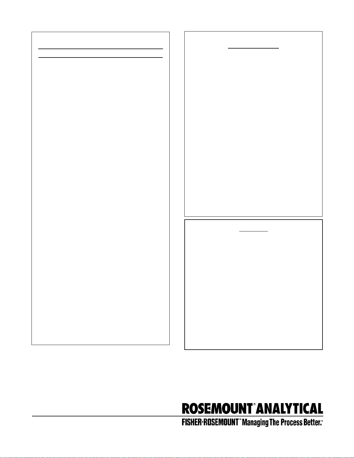
3.1 ANALYZER FRONT VIEW
3.1.1 MAIN CABINET
Part Function
Main Cabinet Splash-proof enclosure protects
analyzer.
Reagent Cabinet Splash-proof enclosure protects
reagents and solenoid valves.
Door Hinges Pin hinges mount doors on main
and reagent cabinets.
Door Latch Secures cabinet door.
Keypad Panel Contains touch buttons for con-
trolling analyzer, digital display,
and status panels.
HB Lamp Indicates when power is ON to
heating bath.
1/2 Amp 1/2 amp fuse for heating bath.
LAMP PS 1 Amp 1 amp fuse for power supply to
colorimeter lamp.
PUMP 1 Amp 1 amp fuse for pump.
XFMR 1 Amp 1 amp fuse for transformer.
Pump On/Off Lighted switch controls power to
pump.
Pump Norm/Hi Switch selects pump speed.
On/Off Main power switch supplies
power to electronics, trans-
former, and heating bath.
Colorimeter Colorimeter assembly Assembly
measures absorbance of the
reacted sample solution.
Waste Drain Pan Drain pan directs waste solu-
tions to waste tube.
Pump Connector Positive fit connector connects
pump to main cabinet electron-
ics.
Heating Bath Positive fit connector connects
Connector heating bath to main cabinet
electronics.
Solenoid Valve #3 Redirects reagent flow to waste
tube during baseline correction
(dependent on chemistry).
Part Function
Pump Assembly Positive displacement, peristaltic
pump moves sample and
reagents through analyzer.
Reaction Vessel Contains chemistry module,
Assembly heating bath, and thermometer.
Chemistry Module Tubing which carries sample
Tubing and reagent into chemistry mod-
ule.
Quick-Disconnect Connects chemistry module tub-
ing and pump tubing harness.
Pump Tubing Tubing which carries sample
Harness and reagents through pump.
Waste Tube Carries waste solutions to drain.
Leak Detector Senses leakage of solutions in
main cabinet, shut pump off, and
activates leak LED.
3.1.2 REAGENT CABINET
Part Function
Cabinet Light Light with on/off switch for view-
ing reagent cabinet.
Solenoid Valve “Phone” jack connectors for
Power Connectors solenoid valve power.
Sample Solenoid Solenoid valve which directs
Valve #1 flow of sample.
Baseline/Standard Solenoid valve which directs flow
Solenoid Valve #2 of baseline solution and fullscale
standard.
Multi-Stream Two to six solenoid valves
Valve Panel mounted on a panel for control
of multiple analysis streams
(Multi-Stream analyzer only).
Multi-Stream Positive fit connector connects
Connector Multi-Stream valve panel to main
cabinet electronics.
Bulkhead Fitting Fitting that directs individual
sample stream to sample valve.
3
CHEMPURE MANUAL SECTION 3
INSTRUMENT DESCRIPTION
FIGURE 3-1 ANALYZER FRONT VIEW
(2X)

4
Button/LED Function
auto multi-stream Press to begin automatic Multi-
Stream analysis (Multi-Stream
analyzer only).
man. baseline Press to begin manual baseline
setting procedure.
set multi-stream Press to program analysis time
for each sample stream (Multi-
Stream analyzer only).
hi alarm Press to set high alarm limit.
dec. loc. Press to set decimal point location.
low alarm Press to set low alarm limit.
power When lit indicates power ON to
circuitry.
rec. f/s Press to output fullscale signal to
external device such as a
recorder.
tube reset Press to display hours before rec-
ommended monthly mainte-
nance.
rec. zero Press to output zero signal to ex-
ternal device such as a recorder.
leak LED When lit indicates leak in main
cabinet.
calibration LED When lit indicates calibration in
progress.
lamp LED When lit indicates colorimeter
source lamp failure.
pump tube LED When lit indicates monthly main-
tenance should be performed.
3.2 KEYPAD PANEL
3.2.1 PANEL
Part Function
Thumbscrews Attaches keypad to analyzer and
secures door to electronics panel.
Digital Display Liquid crystal display reads out
in four digits with adjustable deci-
mal point.
Status Panel Four LEDs indicate leak, calibra-
tion, lamp failure, and hours re-
maining to monthly maintenance.
Sample Stream LEDs indicate sample stream
Indicator currently being sampled and
stream currently being displayed
(Multi-Stream analyzer only).
3.2.2 KEYPAD
Button/LED Function
man. multi-stream Press to manually choose sample
stream (Multi-Stream analyzer only).
/\ Press to increase displayed
value.
enter Press to accept numeric entries or
terminate a procedure.
\/ Press to decrease displayed
value.
auto cal Press to begin automatic calibra-
tion of analyzer.
man. fullscale Press to begin manual fullscale
calibration of analyzer.
CHEMPURE MANUAL SECTION 3
INSTRUMENT DESCRIPTION
FIGURE 3-2 KEYPAD PANEL

5
CHEMPURE MANUAL SECTION 3
INSTRUMENT DESCRIPTION
3.3 ELECTRONICS PANEL
The electronics panel is located directly behind the key-
pad. Access electronics panel by removing thumb-
screws from right side of keypad panel and opening
hinged door.
3.3.1 ELECTRONIC PANEL
Part Function
Keypad Panel Door Opens to access electronics
panel.
Display Board Circuit board contains electron-
ics for keypad and
LCD display.
CPU Board Central processing circuit board
processes the signal fed to the
digital display and any external
devices. Clips are color coded
yellow.
Part Function
Multi-Stream and Circuit board controls Stream
Multi-RS-232C accessory and Interface Board
RS-232C interface. Clips are
color coded purple.
Fault/Analog Circuit board converts Board
signals from analog to digital
and processes signals from
“fault” detectors. Clips are color
coded orange.
Power Board Supplies voltages to electrical
circuitry. Clips are color coded
blue.
FIGURE 3-3 ELECTRONICS PANEL

6
CHEMPURE MANUAL SECTION 3
INSTRUMENT DESCRIPTION
3.3.2 CPU BOARD
Part Function
20 mA Adjust For adjustment of fullscale
Set Screw recorder output signal when
recorder has no span adjust-
ment.
4 mA Adjust For adjustment of zero
Set Screw recorder output signal when
recorder has no span adjust-
ment.
5 V Adjust For adjustment of fullscale
Set Screw recorder output signal when
recorder has no span adjust-
ment.
0 V Adjust For adjustment of zero
Set Screw recorder output signal when
recorder has no span adjust-
ment.
Computer Memory Clears microprocessor
Reset Switch memory.
3.3.3 FAULT/ANALOG BOARD
Part Function
Leak Detector Adjusts sensitivity of leak
Adjust Set Screw detector.
FIGURE 3-4 CPU BOARD FIGURE 3-5 FAULT/ANALOG BOARD
7
CHEMPURE MANUAL SECTION 3
INSTRUMENT DESCRIPTION
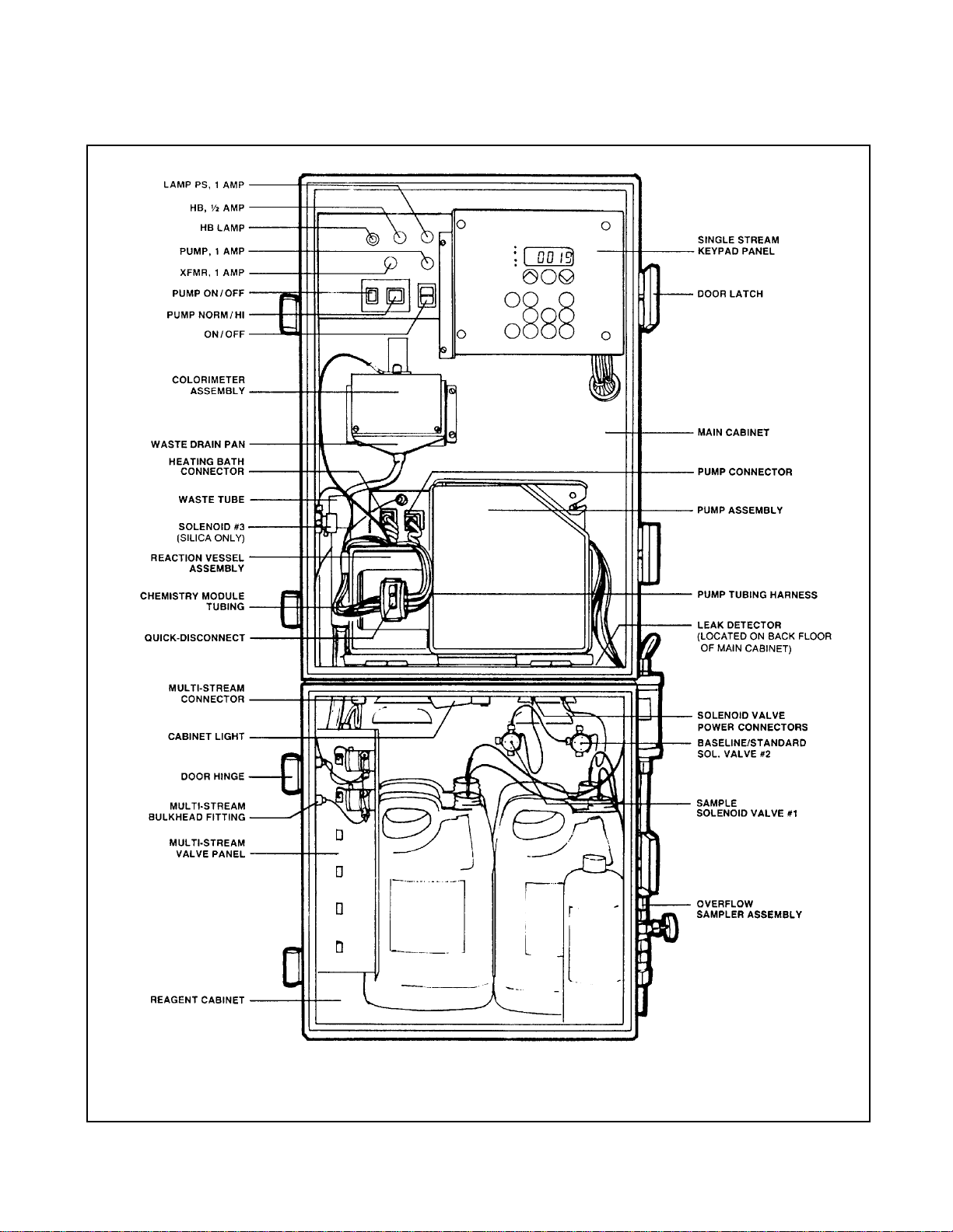
3.4 COLORIMETER
Part Function
Colorimeter Contains and protects Housing
colorimeter and electronics
which measure the absorbance
of the reacted sample solution.
Source Lamp Provides light source for col-
orimeter.
Interference Selects desired wavelength of
Filter Assembly light from source lamp beam.
Sample Flow Cell Sample flows through cell for
analysis.
Sample Flow Sidearm of flow cell which Cell
Inlet receives sample.
Colorimeter Connector for electronic
Connector connection to analyzer.
FIGURE 3-6 COLORIMETER ASSEMBLY
(SEE FIGURE 12-1)

8
Part Function
Quick-Disconnect Male half of tubing Connector
connector which mates with
pump tubing harness.
Colorimeter Inlet Tubing carries sample, after
Tubing appropriate chemical reaction,
to colorimeter.
Thermometer Displays temperature in heating
bath.
Pump Drip Tray Catches any leaks and directs
them to the leak detector.
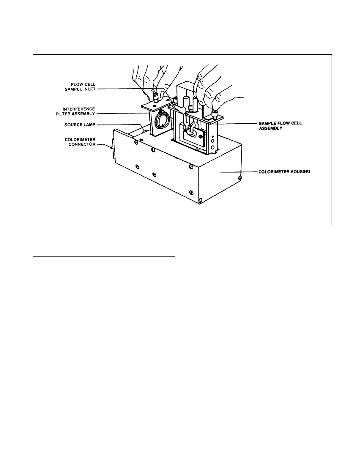
3.5 PUMP AND REACTION VESSEL
ASSEMBLY
Part Function
Pump Housing Contains and protects pump
and reaction vessel assembly.
Pump Positive displacement, peristaltic
pump moves sample and
reagents through the analyzer.
Platen Assembly Maintains pressure on tubing to
ensure consistent flow of sam-
ple and reagents.
Reaction Vessel Contains chemistry module,
Assembly heating bath, and thermometer.
Chemistry Tubing which carries sample
Module Tubing and reagent into chemistry in
reaction vessel assembly.
CHEMPURE MANUAL SECTION 3
INSTRUMENT DESCRIPTION
FIGURE 3-7 PUMP ASSEMBLY COMPONENTS
9
CHEMPURE MANUAL SECTION 3
INSTRUMENT DESCRIPTION
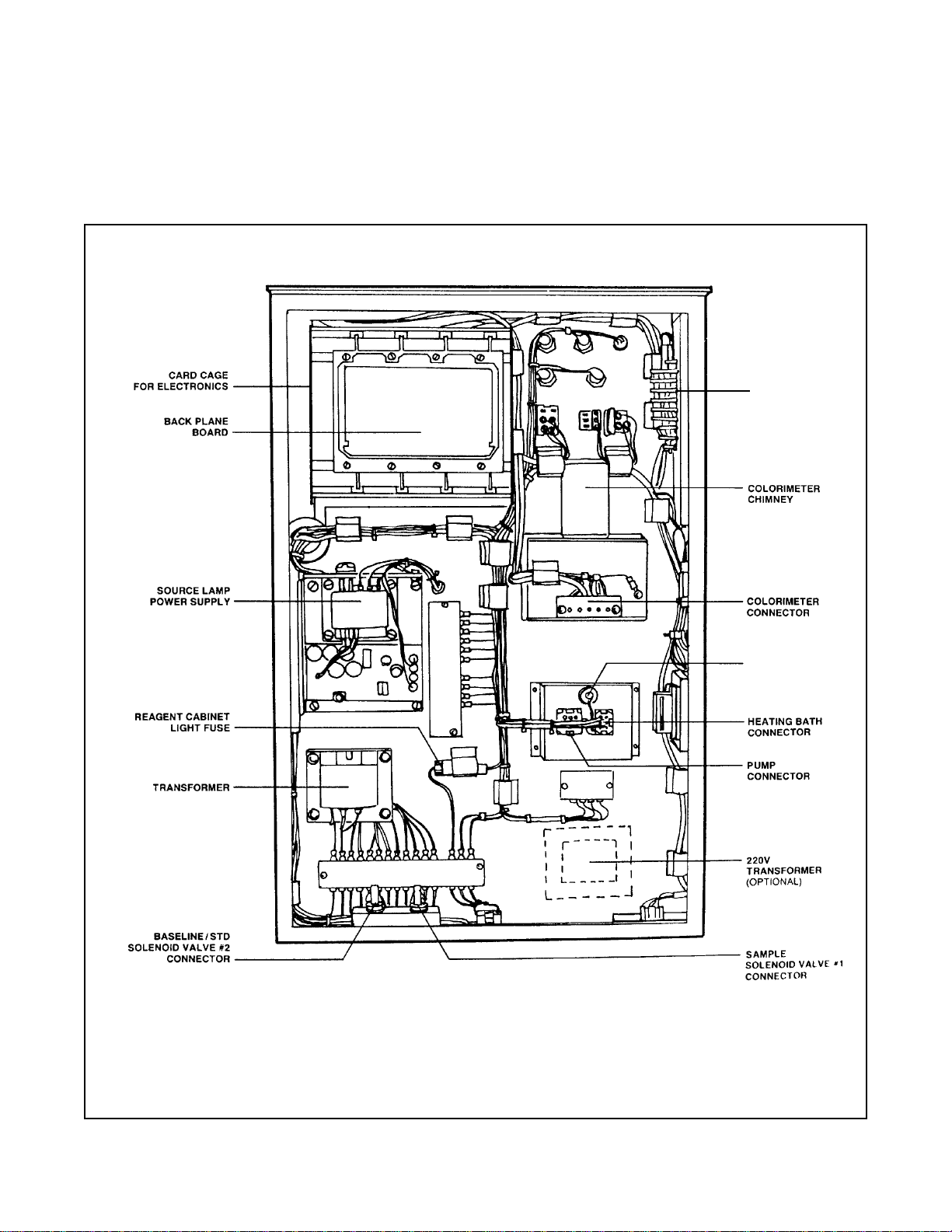
3.6 BACK OF MAIN CABINET
In the back of the main cabinet are a number of elec-
tronic components and connectors.
FIGURE 3-8 BACK OF ANALYZER WITH COVER REMOVED
INPUT/OUTPUT
PANEL
SOLENOID
VALVE #3 CON-
NECTOR

10
CHEMPURE MANUAL SECTION 3
INSTRUMENT DESCRIPTION
3.7 INPUT/OUTPUT PANEL
The input/output panel is located on the upper, left side
of the analyzer.
3.8 COMPUTER INTERFACE
The computer interface ports are located on the lower,
left side of the analyzer.
Part Function
Printer Interface For connection of printer cable.
Relay Output Optional relay contact (Multi-
Stream analyzer only).
RS-232C For connection of computer or
Interface other accessories.
FIGURE 3-9 INPUT/OUTPUT PANEL
FIGURE 3-10
COMPUTER INTERFACE PORTS

11
CHEMPURE MANUAL SECTION 3
INSTRUMENT DESCRIPTION
3.9 OVERFLOW SAMPLER ASSEMBLY
The overflow sample assembly is located is on the
lower right side of the Analyzer (See Figure 3-1)
Part Function
Intake/Regulating Regulates flow of sample into
Valve overflow sampler assembly.
Overflow Tube Assures adequate supply of
sample and reproducible results
by eliminating positive pressure
from sample stream.
FIGURE 3-11
OVERFLOW SAMPLER ASSEMBLY
Part Function
Sample Inlet Tube Tubing which carries sample
from overflow tube to sample
solenoid valve #1.
Air Vent Allows air to escape overflow
tube as it fills with sample.
Overflow Vent Allows excess sample to
escape.
Waste Pipe Carries waste to drain.
12
CHEMPURE MANUAL SECTION 4
INSTALLATION
SECTION 4
INSTALLATION
After the analyzer has been unpacked and all parts
accounted for, install as described in the following
chapter.
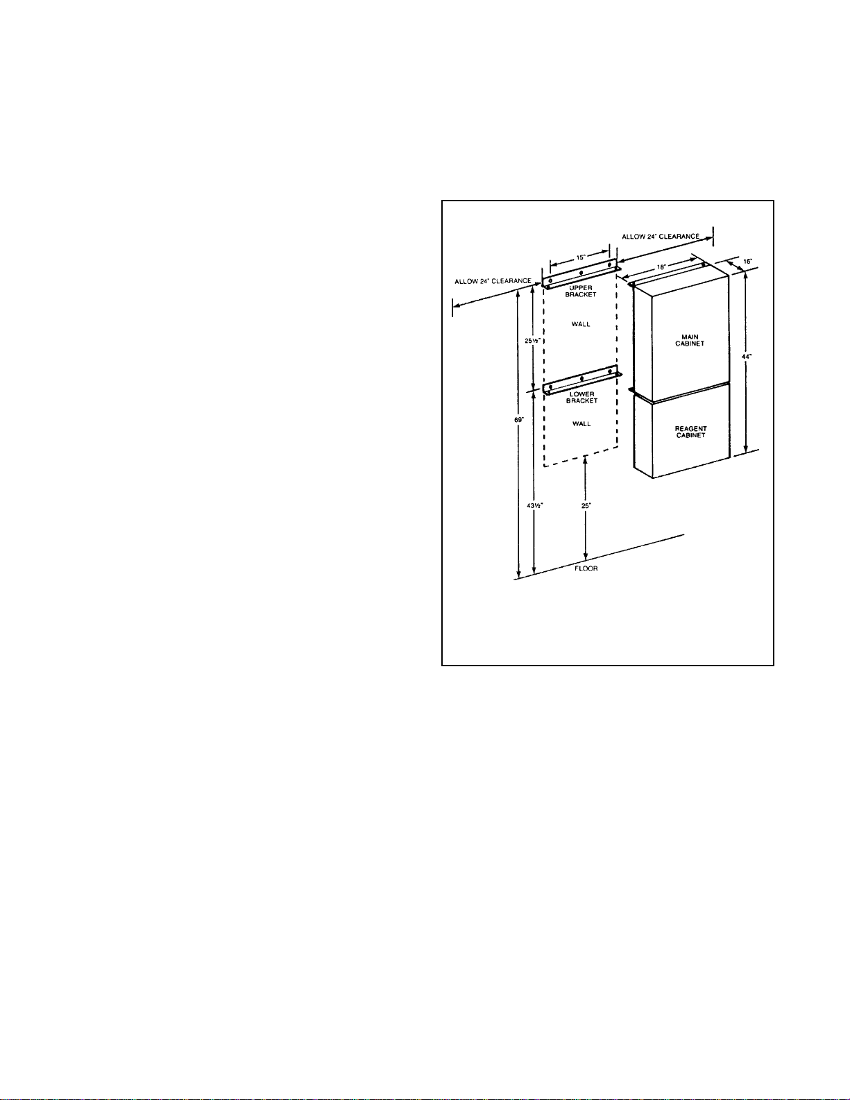
4.1 MAIN CABINET MOUNTING
4.1.1 GENERAL RECOMMENDATIONS:
• Mount the cabinet on a wall or other suitable verti-
cal surface, at least 66" (168cm ) wide and 43 1/2"
(111cm ) off the floor.
• Allow two feet of clearance at the left side of the
analyzer for access to the input/output panel, and
allow for swing of main and reagent cabinet doors.
• Allow 2 feet at the right side for access to the filter
and overflow tube assembly.
• Mount cabinet level or with a slight backward tilt for
proper leak detector operation.
• Mounting surface must be able to support 200
pounds.
• If the analyzer is to be installed out of doors, it must
be suitably sheltered to maintain the following envi-
ronmental conditions: Temperature: 50°F to 90°F,
regulated ±10°F Humidity:
10 to 80%.
To mount the main cabinet, proceed as follows:
1. Drill 6 holes in wall for mounting brackets, as indi-
cated in Figure 4-1.
2. Securely attach “L” brackets to wall using suitable
hardware. (Brackets must be anchored properly to
support 200 pounds.)
3. Attach main cabinet to “L” brackets using four
3/8" x 3/4" bolts, 3/8" split ring washers, and 3/8"
hex nuts.
4.2 REAGENT CABINET MOUNTING
To mount the reagent cabinet, proceed as follows:
1. Loosen the four bolts in bottom of
main cabinet,
leaving approximately 1/4" between washer and
cabinet.
2. Lift reagent cabinet and attach to main cabinet by
placing heads of bolts into the keyhole slots in top
of reagent cabinet and sliding reagent cabinet
back.
3. Tighten screws to attach reagent cabinet to main
cabinet.
4.3 WASTE TUBE INSTALLATION
To install the waste tube, proceed as follows:
1. Guide waste tubing through main cabinet into
reagent cabinet and out the side of reagent cabi-
net.
2. Secure plastic waste tube in clamp in lower right of
main cabinet. See Figure 3-1.
FIGURE 4-1 MOUNTING MAIN AND
REAGENT CABINETS

13
CHEMPURE MANUAL SECTION 4
INSTALLATION
4.4 OVERFLOW SAMPLER ASSEMBLY
To mount overflow sampler assembly, proceed
as follows:
1. Mount overflow sampler assembly on outer, right
side of reagent cabinet using four bolts provided.
See Figure 4-2. (If using IF-100 In-Line Filter see
instruction sheet enclosed with filter for complete
installation instructions.)
2. Place ends of the air vent tubing and overflow
waste tubing into waste pipe.
3. Connect waste pipe to drain.
4. Supply sample stream to regulating/intake valve
with 1/4" tubing (plastic or steel) as follows:
a. Loosen and remove nut and compression fitting
from bottom of regulating intake valve.
b. Slide nut and compression fitting over end of
sample stream tubing.
c. Seat end of tubing in nipple of valve and secure
by firmly tightening nut.
4.5 ELECTRICAL CONNECTIONS
Electrical connections are made to and from the analyz-
er at the input/output panel, located on the left side of
the analyzer. See Figure 3-9.
FIGURE 4-2
OVERFLOW SAMPLER ASSEMBLY

14
CHEMPURE MANUAL SECTION 4
INSTALLATION
FIGURE 4-3 PUMP AND REACTION VESSEL ASSEMBLY
FIGURE 4-4 PUMP PLATEN REMOVAL
This manual suits for next models
12
Table of contents
Other Fisher-Rosemount Measuring Instrument manuals


