Fishing Abilities Freedom Fisher User manual

1
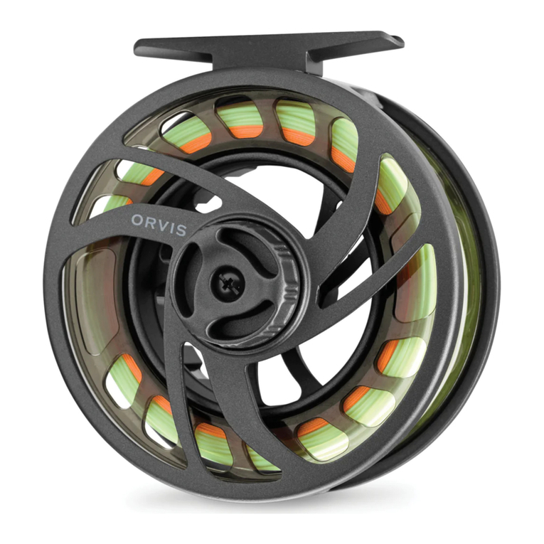
Congratulations on your purchase! The FreedomFISHR™ power-assist
reel system is a powerful and easy to operate mobile fishing device. Under normal
conditions and with proper care, the FreedomFISHR™ is designed to provide years of
trouble-free service and enjoyment. For the best experience, please take a moment to
review the following information before attempting to operate this product.
Fishing Abilities, Inc. reserves the right to change or modify its products, at any time and
without prior notice. Visit fishingabilities.com for the latest updates and product
information.
WARRANTY
The FreedomFISHR™ power-assist reel system is guaranteed to be free from all
manufacturers’ defects for a period of (1) year from the date of purchase. Please refer to
separate manufacturer warranty conditions for Batteries and Mobile Power
Devices included with the FreedomFISHR™ system.
Fishing Abilities, Inc. will repair or replace, at its discretion any product defect. Warranty
does not cover damage caused by abuse, misuse, tampering, user repairs or wear from
use. Warranty is null and void if product is modified, operated with parts or materials not
expressly permitted or if used for any other purpose than intended.
Warranty and Purchase Agreement are not transferable. Please contact Fishing Abilities,
Inc. to reconcile any warranty issues.
SERVICE
For replacements parts, repairs and periodic maintenance relating to the
FreedomFISHR™ power-assist reel contact Fishing Abilities, Inc. Fishing Abilities,
Inc. is solely authorized by Shimano to perform all repairs on reels converted for use as
FreedomFISHR™ power-assist reel systems.
Fishing Abilities, Inc.
22770 Adams Rd.
South Bend IN, 46628
(574) 273-0842
info@fishingabilities.com

2
CONTENTS
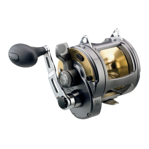
•FreedomFISHR™Power-Assist Reel
•CONTROLLER ASSEMBLY
•SMART BATTERY KIT
Includes: Lithium-Ion SMART BATTERY, Charger, Manual, and Belt Clip with 3M VHB™ Tape)
Alcohol Swab and Shimano Syncopate Instruction Guide

3
WARNING
The FreedomFISHR™is a low voltage, electro-mechanical device posing
little risk for electrical hazard and injury. However, NEVER use or operate this device
without covers installed, if any components show signs of damage, or if the product
has been exposed to water. Disconnect all power cables in case of damage and after
each use. Contact Fishing Abilities, Inc. for parts and service.
The user must determine the suitability of this product and assumes all
risk and liability for operation.
SET UP
1. After unpacking, verify that all contents are present.
2. FreedomFISHR™power-assist reel
1. Locate the Anti-Reverse Lever on the underside of the reel. Refer to the Shimano
Instruction Guide for description of reel components.
2. Verify that the Anti-Reverse mechanism is engaged (Lever tab flipped to motor
side of reel and Lever tab mounting screw head is hidden).
3. Mount FreedomFISHR™ power-assist reel to rod.
3. CONTROLLER ASSEMBLY
1. While holding the rod and FreedomFISHR™,
determine the best placement for the Rocker Switch
actuator. This is usually underneath the thumb when
holding the rod and reel in a natural position. Mount
the Rocker Switch enclosure to the rod using the
included cable ties.
2. Connect power lead from the
switch enclosure to the
FreedomFISHR™ motor input.

4
4. SMART BATTERY
1. Abide by all safety warnings and disclosures listed in the enclosed battery user
manual.
2. Follow these steps to properly charge the SMART BATTERY:
(a) Place battery switch in "OFF" position. See side of battery enclosure for "ON
OFF" reference mark.
(b) Plug wall charger DC jack into battery.
(c) Connect wall charger AC plug to an appropriate receptacle. The battery LED
light will glow RED. The charger plug LED light will glow GREEN.
(d) IMPORTANT: Turn battery switch "ON." If battery switch remains "OFF"
charging will NOT take place! The charger plug LED light changes from
GREEN to RED.
(e) Full charge is achieved when charger plug glows GREEN, usually between 8
and 12 hours.
(f) Turn OFF battery switch before disconnecting leads.
(g) Remove Charger from battery. Store Charger for future use.
3. An optional Belt Clip is included with each battery pack. Once installed, the
battery and PWM enclosure can be easily attached to a belt, allowing full user
mobility.
(a) To assemble the battery belt clip, orient the battery face to the side
OPPOSITE the two 3M Dual Lock® strips.
(b) Use the supplied alcohol swab to wipe and prepare the battery
surface.
(c) Use the supplied alcohol swab to wipe and prepare the shorter side
of the belt clip.
(d) Wait until the surface alcohol completely evaporates from all
surfaces.
(e) Peel release paper from one side of the 3M VHB™ Tape.
(f) Align onto short side of belt clip. Press firmly to set.

5
(g) Remove the remaining release paper from the 3M VHB™ Tape.
(h) Belt clip should be mounted
lengthwise, inline and centered on
the battery enclosure. Thick end of
the belt clip should be approximately
1/2" below the battery end with LED,
switch and jack. Press firmly to set
tape adhesive.
4. Orient the PWM enclosure dial in the same
direction as the LED, switch and jack of the battery unit. Affix the PWM enclosure
to the battery by joining both 3M Dual Lock® surfaces together. Test that both
components are securely held by the 3M Dual Lock® strips.
5. Make sure battery is OFF. Then
plug in PWM power lead into
battery IN/OUT jack.
6. Turn ON battery switch. Battery
LED indicator will illuminate.
System will be powered and ready
for use.

6
START UP
1. Place reel in cranking mode. Make certain that the bail is NOT open for casting.
2. Rotate PWM dial 1/4 turn to activate the PWM.
3. While holding the rod and reel normally, push the Rocker Switch in any direction
to cycle the reel.
4. Next push the Rocker Switch in the opposite direction and check rotation. Note
which Rocker Switch position actuated PRESET and HIGH speed.
5. For PRESET speed operation, user may set the PWM dial to any
preferred speed up to maximum. Once chosen, the PRESET speed position of
the Rocker Switch will recall the assigned speed. PRESET speed preference
may be changed at any time
by rotating the PWM dial to
another position.
6. At any time, user can instantly
select HIGH speed (FULL
Power) by simply pressing the
Rocker Switch in the opposite
direction. HIGH speed is
immediately available once
the battery is connected and
turned "ON."
OPERATION
1. After casting the line, return the bail to cranking mode, by hand. Do NOT close
the bail using the motor and NEVER attempt to rotate the bail manually.
Doing so will damage the gear motor drive assembly and require service.

7
2. An integrated protection circuit actively monitors the electrical current
consumption from inside the battery housing. Should a circuit overload occur
(caused from binding, motor bail tripping, or operating under high
load), the circuit breaker instantly disables all power to the motor and PWM. A
sign of this condition is that the battery LED indicator light goes off whenever the
Rocker Switch is pressed. After correcting any problem, restore power by turning
the battery switch OFF then ON again.
3. The Front Drag must be set correctly for line and proper motor performance.
Over-setting the drag may cause the SMART BATTERY circuit breaker to trip.
4. HIGH speed remains available regardless of the PWM dial position. Should a
circuit malfunction occur, this bypass feature allows limited HIGH-speed use
only.
5. The PWM speed selector dial also employs an integrated ON/OFF circuit switch.
Be sure that PWM dial is clicked ON before attempting to choose a PRESET
speed position OR if experiencing lack of PRESET speed functionality.
6. Always turn OFF all power and disconnect the battery after each use.
Fishing Abilities, Inc.
22770 Adams Rd.
South Bend IN, 46628
(574) 273-0842
Table of contents

