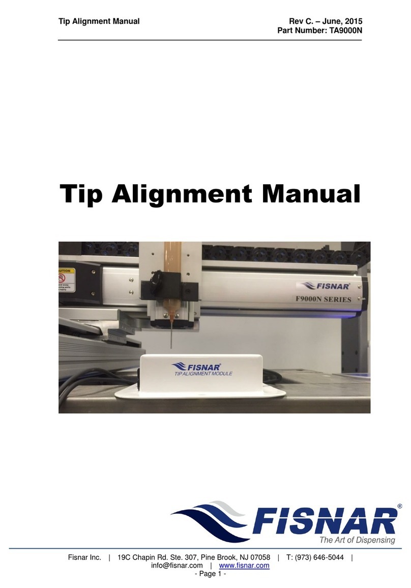
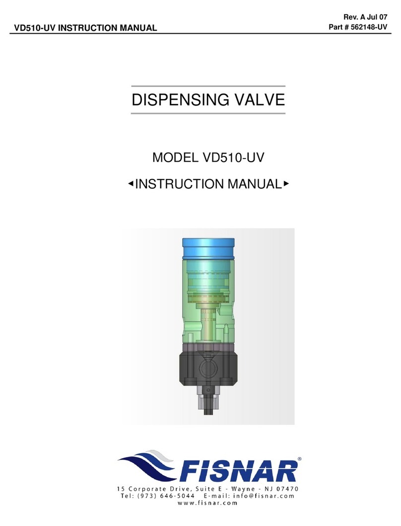
FISNAR VDP100 User manual

VDP100 INSTRUCTION MANUAL
Rev. A - October, 2013
DISPENSING VALVE
MODEL VDP100
◀INSTRUCTION MANUAL▶

VDP100 INSTRUCTION MANUAL
Rev. A - October, 2013
2 | P a g e
CONTENTS
1. Safety - - - - - - - - - - - - - - - - - - - - - - - - - 3
2. Introduction - - - - - - - - - - - - - - - - - - - - - - - - - 5
3. Specification - - - - - - - - - - - - - - - - - - - - - - - - 6
4. Operation - - - - - - - - - - - - - - - - - - - - - - - - - - - 7
5. Disassembly / Reassembly - - - - - - - - - - - - - - - - - - - - - 8
6. Exploded View / Parts List- - - - - - - - - - - - - - - - - - - - - - 9
7. Troubleshooting - - - - - - - - - - - - - - - - - - - - - - - - - - 10
8. Dimensions - - - - - - - - - - - - - - - - - - - - - - - - 11
Read the manual before installation and maintenance

VDP100 INSTRUCTION MANUAL
Rev. A - October, 2013
3 | P a g e
SECTION 1
GENERAL SAFETY WARNINGS
1. Equipment Misuse Hazards
Any misuse of the dispensing equipment or accessories such as over-
pressurizing, modifying parts, using incompatible chemicals and fluids, or using
worn or damaged parts, can cause item to rupture and result in fluid splashing in
the eyes or on to the skin.
Never alter or modify any part of this equipment, doing so could cause it to
malfunction.
Check all dispensing equipment regularly and repair, or replace worn or
damaged parts immediately.
Always wear protective eyewear, gloves and clothing, as recommended by the
material and solvent manufacturers.
Never exceed the maximum air inlet pressure of 7 bar (100 psi).
Never exceed the maximum material inlet pressure of 7 bar (1,100 psi).
Do not exceed the maximum working pressure of any component or accessory
used in the system.
Be sure that all materials and solvents used are chemically compatible with the
wetted parts. Always read the manufacturer's literature before using material or
solvent in this pump.

VDP100 INSTRUCTION MANUAL
Rev. A - October, 2013
4 | P a g e
2. Hose Safety
High pressure fluid in the hoses can be very dangerous. If the hose develops a
leak, split or rupture due to any kind of wear, damage or misuse, the high
pressure spray emitted from it can cause material to splash in the eyes or on the
skin. Tighten all fluid connections securely before each use. High pressure fluid
can dislodge a loose coupling or allow high pressure spray to be emitted from the
coupling.
Never use a damaged hose. Before each use, check the entire hose for cuts,
leaks, abrasion or damage or movement of the hose couplings. If any of these
conditions exist, replace the hose immediately.
Do not try to re-couple high pressure hose or mend it with tape or any other
device. A repaired hose cannot safely contain the high pressure fluid.
Handle and route hoses carefully, do not pull on hoses to move equipment. Do
not use materials which are not chemically compatible with the hose.

VDP100 INSTRUCTION MANUAL
Rev. A - October, 2013
5 | P a g e
SECTION 2
INTRODUCTION
The VDP100 is an adjustable, pneumatically-operated, positive displacement valve
designed for dispensing constant volume shots of low to medium viscosity materials
within 1%, such as oil and grease. The VDP100 valve has a range up to 0.9cc.
The model VC1195N is a suitable 4-way valve controller for the VDP100 double acting
metering valve.
4-Way Valve Operation
The valve is cycled by applying air pressure to the air ports. Low fluid pressure is
required for low to medium viscosity materials.
Shot sizes may be fine-tuned by turning an adjustment control knob at the side of the
valve.
A. Air Supply Line
B. Fluid Supply Line C. Fluid Inlet Fitting
D. Air Inlet Fitting E. Hose Tie
17. Valve Housing

VDP100 INSTRUCTION MANUAL
Rev. A - October, 2013
6 | P a g e
SECTION 3
SPECIFICATION
Operating Air Pressure
4 - 5 kgf/cm² (56psi –71psi)
Material Delivery Pressure
MAX 80kgf/cm (1137psi)
Valve Structure
Metering Type (0.1cc –0.9cc)
Driving part material
Material Body : AL(hard coating)
Drive Body : AL(hard coating)
Packing : O-ring(Viton), PS ring
Connecting Ports
Operating Air Inlet : PT 1/8
Exhausting Outlet : PT 1/8
Material Inlet : PT 1/8
Needle Adapter : PT 1/4

VDP100 INSTRUCTION MANUAL
Rev. A - October, 2013
7 | P a g e
SECTION 4
OPERATION
1. Commissioning the Valve
a. Open the air line (A) and fluid line (B) of the dispensing valve.
b. Keep cycling the machine until all air in the line is removed.
c. Purge 2-3 shots to waste.
The valve is now primed and ready for use.
2. Operating the Valve
a. Activate the controller to actuate the valve
b. Adjust the Stopper as needed. Secure it in place with the nut afterwards.
1. Needle
9. Stopper nut 10. Stopper
17. Valve Housing A. Air Line
B. Fluid Line

VDP100 INSTRUCTION MANUAL
Rev. A - October, 2013
8 | P a g e
SECTION 5
DISASSEMBLY / REASSEMBLY
ISOLATE ALL AIR AND MATERIAL FEEDS FROM
THE VALVE PRIOR TO SERVICING.
1. Disassembly
a. Remove the four Bolts (16) from the Change Body (17).
b. Remove the bolts (7), disassembling the Metering Body (1) and Metering
Cap (6).
c. Disassemble the Stopper (10), Stopper Lock Nut (9) and Piston (3) in this
order.
d. Disassemble the Needle (12), Needle Adapter(13) and Bolts(14).
e. Disassemble the Low Base (15) and Change Body (17), then remove the
Bushing (20).
f. Unfasten the Bolts (27) from the Cylinder (26).
g. Disassemble the Cylinder Cap (22) then remove the Shaft (24) from
Cylinder (26).
2. Reassembly
a. Lubricate the inside of the Change Body (17), install the Bushing (20).
b. Lubricate the Shaft (24) and install into the Change Body (17).
c. After placing the Shaft (24), install the bolt (14) of the Low Base (15) and
the Bolt (27) of the Cylinder (26).
d. Place the Piston (3) on the Metering Body (1), connecting with Metering
Cap (6).
e. Install the Stop Washer (8), Stopper Lock Nut (9) and Stopper (10) in this
order.
f. Connect the Change Body (17) and the Metering Body (1) with the Bolt
(16).

VDP100 INSTRUCTION MANUAL
Rev. A - October, 2013
9 | P a g e
SECTION 6
EXPLODED VIEW AND PARTS LIST
1. Metering Body (Aluminum)
2. O-ring
3. Piston(Bronze)
4. O-ring
5. O-ring
6. Metering Cap(Aluminum)
7. Bolt
8. Stopper Washer
9. Stopper Lock Nut(Stainless Steel)
10. Stopper (Stainless Steel)
11. O-ring(P5)
12. Needle
13. Needle Adapter
14. Bolt
15. Low Base(Aluminum)
16. Bolt
17. Change Body(Aluminum)
18. O-ring
19. Quid Ring
20. Busing(Bronze)
21. O-ring
22.Cylinder Cap(Aluminum)
23. O-ring(AN017)
24. Shaft(Stainless Steel)
25. Cylinder
26. Bolt
27. Bolt(M4*45)

VDP100 INSTRUCTION MANUAL
Rev. A - October, 2013
10 | P a g e
SECTION 7
TROUBLESHOOTING
Shaft does not move
oCheck power of the air supply line and other equipment.
oCheck for cured material at the valve outlet.
Material leaks
oIf it leaks from the Needle (12), unfasten the Metering Cap (6) and clean
the O-ring (2) on the Piston (3). If it happens again after cleaning, change
the O-ring (2).
oIf the liquid leaks from the body of the Valve, clean the Bushing (20), Quid
Ring (19) and O-ring (18). If the leak continues, replace all parts.
oReplace the Shaft (24).
Valve does not dispense
oCheck the Stopper (10) position and the actuation of the Shaft (24).
oCheck the material feed line.
oCheck the power of the air supply line and other equipment.
Air bubbles in fluid
oTurn the valve upside down (or at least 90ofrom the horizontal) and
dispense 2-3 shots.
oCheck the material supply.

VDP100 INSTRUCTION MANUAL
Rev. A - October, 2013
11 | P a g e
SECTION 8
DIMENSIONS

Table of contents
Other FISNAR Control Unit manuals
