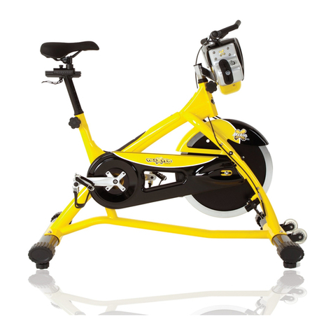
fitness Gallary RX125v3 User manual

RX125v3
INDOOR CYCLE

2

3

4
Assembly Drawing

5
Assembly
Step one
Attach the front (18) and rear feet (14) to the frame using the nuts (8), washer (9)
and bolts (10).
Step two
Attach the handlebar post (22) by inserting it into the head tube of the frame.
Use the release lever to adjust and tighten the height to the desired position.
Attach the handlebar slider (23) on the handlebar post (22), use release lever (17)
to adjust and tighten the handlebar into position. There is screw on the back of
the console (57) take this off and slide the console (57) onto the console bracket.
Secure the console to the console bracket with the screw from the back of the
console. Connect the cable (58) to the back of the console (57) and make sure
the other side of the console cable (58) is connected securely to the cable
coming from the frame. Additionally, make sure that the cable stopper (30) is
plugged into the hole that the lower cable connections came through.
Step three
Insert the seat post (43) into the seat tube on the frame. Attach the saddle (1)
into seat slider (42). Then tighten seat clamp’s screw. Insert the seat slider (42) into
the seat post (43) and fix. Using release lever (6) adjusts and tightens the height
in the desired position.
Step four
Attach the pedals (11) into the crank arms (20)(21), each pedal is marked with L
(left) or R (right), make sure it’s assembled on the correct side. (R: means rider’s
right side). Be careful to align the threads correctly to avoid damaging them.
Applying a little grease on the threads will help the pedals to screw in easily and
correctly, tighten using a 15mm spanner; both pedals should tighten towards the
front of the spinning bike. Attach the bottle cage (26) and bracket (48) on the left
side of frame using the screw (25).
Adjusting the resistance
Adjust the exercise resistance on the spinning bike using the tension knob (24) to
loosen (-) or tighten (+).

6
Exploded Drawing

7
Part list
No.
Name
Unit
No.
Name
Unit
1
Saddle
PC
33
BB bearing
PC
2
Alloy bind clamp ( L )
PC
34
BB Axle with plate
PC
3
Spring for release lever
PC
35
Flywheel axle
SET
4
Alloy bind clamp ( R )
PR
36
Fixed wheel nut
5
Washer for release lever
PC
37
Flywheel bearing
6
Release lever
PC
15
Flywheel security nut (7t)
7
Crank bolt
PC
63
Rubber cover for flywheel
8
Foot tube nut
PC
38
Axle bolt for moving wheel
PC
9
Foot tube washer
PC
39
Moving wheel
PC
10
Foot fixing bolt
PC
40
Plastic washer for release lever
PC
11
Pedal
PR
41
Fixed bolt for release lever
PC
12
Front / Rear foot tube end cap
PC
42,29
Seat slider w/ end plug
PC
13
Foot tube adjuster pad
PC
43
Seat post
PC
14
Rear foot tube complete
SET
44
Stainless washer for release lever
PC
15
Flywheel security nut (7t)
PC
45
Belt
PC
16
Flywheel adjuster bolt
PC
46
Spring
PC
17
Handle bar release lever
w/washer
PC
47
Outer chain guard bolt M5
PC
18
Front foot tube complete
SET
48
Cage bracket
PC
19
Right belt guard
PC
49
Flywheel (complete)
SET
20
Left crank arm
PC
50
Rubber sleeves
PC
21
Right crank arm
PC
51
Fixed bolt for tension knob casing
PC
22,27,28
Handle bar post w/rubber clip
PC
52
Idler w/bearing, clip
SET
23
Handle bar w/slider
PC
53
Rubber sealed
PC
24
Tension knob set (complete)
SET
54
Handle for tension knob
PC
25
Bolt for bottle cage
PC
55
Casing for tension knob
PC
26
Bottle cage
PC
56
Bolt for tension knob handle
PC
27
Rubber eyelet for handle bar
post
PC
57+58+
60+65
Computer w/ cable, sensor cable,
clamp complete set
SET
28
End cap
PC
58
Upper cable
PC
30
Cable plug
PC
59
Washer for plate
PC
31
Left belt guard
PC
32
Nut for bottle cage
PC
61
Belt pulley with screw, magnet
PC

8
No.
Name
Unit
No.
Name
Unit
62
Fixed bolt for plate
PC
67
Bolt for protection tube
PC
63
Rubber cover for flywheel
PC
68
Washer for protection tube
PC
64
Adjuster cable guide
PC
69
Bottom tube cover w/adhesive tape
PC
65
Sensor cable
PC
66
Flywheel protection tube
PC
G01
Magnetic holder w/magnetic set
SET
Instruction Use
1) The bike is designed to be used as a “spin “ cycle in fitness studios and health clubs. It
has a fixed wheel driven flywheel and should only be used under professional
supervision.
2) Installation –it is important that the bike is correctly assembled and we recommend
that suitably qualified personnel carry out installation and assembly.
3) Handlebar and seat adjustment. It is important that the handlebar and seat are set at
the correct height for your body. Ask your instructor for assistance. Adjusting the
handlebar height-Undo the release lever that is located where the handlebar post fits
into the frame. Slide the handlebar post up or down to the required height and
retighten the release lever. Make sure it is securely tightened and that there is no
lateral or vertical movement of the handlebar. The handlebar position can also be
adjusted forwards or backwards. Undo the Release lever located below the
handlebar slider. Slide the handlebar assembly forwards and backwards until you
reach the required position. Then securely re-tighten the Release lever.
Adjusting the seat height- undo the release lever located where the seat post fits into
the frame. Adjust the seat to the required height. Then retighten the release lever.
Make sure it is tighten enough to prevent the seat from twisting side to side. The seat
position can be adjusted forwards and backwards. Undo the release lever located
directly side of the seat slider. Loosen the release lever then slide the seat to the
required position. Then make sure the release lever retighten.
4) Pedals and toe straps- your feet should be securely positioned in the toe clips during the
exercise. Put your foot as far forwards as you can into the toe-clip and then pull the
strap tight.
5) The bike should operate on a level surface with no lateral movement. There is height
adjuster pad located on either side underneath of the foot tube. Turn these pads
clockwise or anti-clockwise until the bike is totally stable on the ground.
6) Emergency brake –This bike can be instantaneously stopped by rotating the red tension
lever (24) completely forward.
7) Maintenance –It may be unsafe when loosen bolt on the parts or noise on the flywheel,
please contact your supplier. Like any other mechanical cycling device, the bike
should be regularly maintained. Ask your supplier for a detailed maintenance
program.

9
Maintenance Chart
No
DESCRIPTION
Daily
Weekly
Monthly
Quarterly
Annually
1
Keep machine clean: Wipe
machine down with clean & dry
fabric to clear dirt & sweat.
X
2
Wipe Anti-rusty cream or similar on
the seat post set, handlebar set
X
3
Visual check
X
4
Check security of handle bar post
& seat post
X
5
Check security of saddle
X
6
Remove handlebar post and
clean tube
X
7
Remove seat and clean tube
X
8
Check brake pads for wear-align
X
9
Check brake adjustment
X
10
Check security of all knobs &
release lever
X
11
Check toe straps for signs of wear
X
12
Check crank bolts and re-tighten
X
13
Make sure pedals are screwed in
X
14
Check the magnetic holder in
correct position
X
15
Check belt tension
X
16
Wipe the anti-rust oil on the
middle range of flywheel surface
X
17
Check bottom bracket
X
18
Check flywheel bearings
X
19
Full service-frame inspection

10
CONSOLE SPECIFICATIONS :
Cadence bar graph : 0-200RPM, 10RPM per bar.
RPM measure : 0-240RPM
Speed : 0-96 KM/H (0-60MPH)
Pulse : Analog signal, 30-240 BPM
Watt : 0-999 Watt
Time : Countdown range : 1-99 minutes
Count up range : 00:01 –99:59
BATTERY INSTALLATION :
1) Remove the battery cover from the back of the computer.
2) Insert two (2) AAA batteries into the battery compartment and reinstall the battery cover.
3) When the battery voltage becomes too low, the “Low battery “indicator will appear on the console
display, indicating that the batteries need to be replaced.
MEASUREMENTS DEFINITION :
1) TIME : Time is measured in minutes and seconds (min : sec).
There is a time of day clock and a workout time clock. The workout time will count up or down during
pedaling. If the user stops pedaling, the time count will stop after 3 seconds.
2) RPM / CADENCE : Cadence is the number of pedal revolutions per minute
(RPM). The average RPM value is shown on the bar graphic.
3) SPEED : The approximate speed of the wheel can be shown in kilometers per
Hour (KM/H) or miles per hour (MPH).
4) DISTANCE : The virtual distance traveled on the bike during the workout. The
distance is based on the speed of the wheel and the dimension of a wheel similar to the flywheel.
5) WATT : The actual power measured at any time during the workout. The watt value is based on the
resistance level and the wheel speed.
6) KCAL : The approximate level of calories burned during the workout.
7) HEART RATE : The average heart rate value emitted from the chest strap during the workout.
ELECTRONIC CONSOLE OPERATION

11
1) QUICK START : The console will go to power saving mode when remaining idle for several minute. To start
the console again, press any key.
2) MODE SELECTION : Press the left-hand key to select the measurement to be shown on the bottom of the
display ( Speed, distance, time or clock ).
CONSOLE OPERTION

12
3) SET THE HEART RATE ALARM : To activate or deactivate the heart rate alarm,
Press the right-hand key. When the alarm is ON, the alarm icon appear on the display and a “beep” will
sound to indicate that your heart rate is either above or below the target zone.
4) SET THE WORKOUT TIME, HEART RATE LIMIT & SPEED UNIT : To set the workout time and heart rate target
zones, press the left-hand key until SPEED indicator is displayed, then press the right-hand key for 5 seconds,
The TIME indicator will be flashing, press the right-hand key to adjust the workout time. To set the heart
Rate limit, press the left-hand key to select the heart rate target zone settings. The first limit to be set is the
upper one. Use the right-hand key to adjust the upper value. Once the desired value is set, press the
left-hand key to switch to the lower value setting. Use the right-hand key to adjust the lower value.
To change the speed measurement unit from

13
KM/H to MPH, press the left-hand key until the MPH or KM/H appears at the bottom of the screen, then
use the right-hand key to switch from one unit to the other. When the values are properly set, wait about 8
seconds and the screen will return to the standard display.
5) SET THE TIME OF DAY : To set the time of day (CLOCK), press the left-hand key until the CLOCK appears,
then press the right-hand key for 5 seconds, The 24H or 12H indicator will flash on the display. Press the
right-hand key to select the 24H or 12H mode.
Press the left hand key to navigate between the 24H/12H, hours and minutes settings, press the right-hand
key to adjust the hours and minutes settings. When the clock is properly set, wait about 8 seconds and the
screen will return to the standard display.
6) RESET : To reset the accumulated values, press and hold the left-hand key for about 5 seconds, the values
for AVG Speed, AVG Pulse, Time, Dist, and KCAL will return to zero.
7) CARING FOR YOUR CONSOLE : The console is water resistant, but NOT waterproof. An excessive exposure
to water will void the warranty. You can clean the outside of your console with a lightly damp cloth. The
console is a sealed unit and should not be opened other than for changing the batteries by opening the
battery cover in the back.
8) USING THE HEART RATE TRANSMITTER : To measure the heart rate. The user must wear the chest strap
(optional). At the beginning of the workout, you may need to lightly dampen the two sensors (electrodes)
on the chest strap with order in order to get an accurate signal. The console is also compatible with analog
POLAR chest strap.
TROUBLESHOOTING :
1) IF NO DISPLAY ON CONSOLE :
a. Hold down any key to bring the console to a “QUICK-STRAT “mode.
b. Make sure the batteries of the console are properly installed and provide enough voltage.
2) NO HEART RATE SIGNLA DISPLAYED :
a. Make sure your chest strap is worn correctly and that there is moisture under the electrodes.
b. Relocate the bike away from any equipment that could potentially interrupt radio frequency signals,
such as DVD player, television, etc.
3) HEART RATE SIGNAL GETS INTERUPTED OR DROPS OUT :
a. Make sure there is a minimum distance of 36 inches between the console and other users’chest
straps.
b. Make sure the chest belt is properly adjusted on your chest and that the electrodes are in contact
with your skin.

14
Limited Warranty
This product carries the following guarantee against manufacturing
defects:
* Frame is warranted for 2 years from the date of purchase.
* Components are warranted for 1 year.
* Warranty is only valid for the original purchaser.
* Labor and freight charges are not included.
* Normal wear, neglect, abuse, accidents, improper assembly or
maintenance, or the installation of parts or accessories not
compatible with the original intended use of the bike, as sold, are
not covered by the warranty.
* Neither does it cover any corrosion caused by failure to clean the
bikes on regular basis.
* This warranty is limited to the repair or replacement of the defective
part at no cost. The supplier shall in no event be responsible for
consequential, special damages, and any parts failures, breakages
or injuries resulting from misuse of the machine or failure to follow
the recommended maintenance procedures.
* Warranty claims must be through an authorized dealer, and
replacement parts will normally be dispatched to you. We
recommend you held a small stock of basis spare parts, as well as a
tool kit to cover the regular maintenance routines.
* The Limited Warranty is the only express or implied warranty
applicable to original supplier. Any implied warranties, including
warranties of merchantability and fitness shall be limited in scope and
duration in accordance with this limited warranty.

15

16
INDOOR CYCLE
Table of contents
Popular Exercise Bike manuals by other brands

Sunny Health & Fitness
Sunny Health & Fitness SF-B121021 user manual

Monark
Monark 827E instruction manual

Stamina
Stamina 1310 owner's manual

American Fitness
American Fitness SPR-BK1072A owner's manual

Cateye
Cateye CS-1000 (CYCLO SIMULATOR) Service manual

BH FITNESS
BH FITNESS H9158H Instructions for assembly and use


