Fitness Quest Brutus 655 User manual

655
HOME GYM

2
Congratulations on purchasing your
Brutus®655 Home Gym
With this product in your home, you have everything you need to start your own workout program to tone
andfirmthemajormusclegroupsofyourupperandlowerbody.Thisisvitalforallofus,regardlessofage,
sex, or fitness level, and regardless of whether your primary goal is toning, health maintenance, or more
energy for daily activities.
Proper exercise, including a low fat diet, strength training and aerobic exercise, tones and conditions the
muscles we use every day to stand, walk, lift, and turn. It can actually transform our body composition by
reducing body fat and increasing the proportion of lean muscle in our bodies.
Be sure to read through this Owner’s Manual carefully. It is the authoritative source of information
about your Brutus®655 Home Gym.
Retain this manual for future reference.
Table of Contents:
Important Safety Instructions.....................................................3
CommentsorQuestions&CartonInformation....................................4
HardwareIllustrations........................................................................5-6
PartsIdentification.............................................................................7-9
PartsList................................................................................................10
AssemblyInstructions....................................................................12-35
Owner’s Purchase Record..........................................Back Cover

3
Know your heart rate and / or pulse, and your physician recommended target heart rate training
zone.
Proper medical clearance is recommended for anyone beginning and exercise program especially
if you are over 35 years of age or suffer from heart respiratory problems.
Warm up before any exercise programs with 8 minutes of aerobic activity, followed by stretching
from head to toe.
Wear comfortable clothes that allow freedom of movement and that are not tight or restricting.
Wear comfortable shoes made of good support with nonslip soles.
Breathe naturally, never holding your breath during an exercise.
Perform exercises consistently with proper technique and pass through a full range of motion.
Always use a spotter for safety.
Avoid over training. You should be able to carry on a conversation while exercising.
After an exercise session, cool down with slow stretching, cycling or walking.
This machine should not be used by or near children.
Invalids, or disabled persons must have medical approval before using this machine and should be
under close supervision when using any exercise equipment.
Use this machine only for its intended use as described in this manual. Do not use attachments not
recommended by the manufacturer.
Do not put hands, feet, or any foreign objects on or near this machine when in use by others.
Always use this machine on a level surface.
Never operate the machine if the machine is not functioning properly.
Start exercise slowly and gradually increase the amount of resistance.
Iftheuserexperiencesdizziness,nausea,chestpain,oranyotherabnormal symptoms, stop exercis-
ing at once and consult a physician immediately.
1.
2.
3.
4.
5.
6.
7.
8.
9.
10.
11.
12.
13.
14.
15.
16.
17.
18.
IMPORTANT SAFETY INSTRUCTIONS
Read all instructions before using this machine.
KEEP THESE INSTRUCTIONS
CAUTION:
Exercise of a strenuous nature, as is customarily done on this equipment,
shouldnotbeundertakenwithout first consulting a physician. Nospecifichealth
claims are made or implied as they relate to the equipment. Measurements
made by the equipment are believed to be accurate, but only the measure-
ments of your physician should be relied upon

4
Comments or Questions?
Dear Customer,
CongratulationsonyourpurchaseoftheBrutus® 655 Home Gym.
We’re sure that you will be completely satisfied with the product we invite your comments so that we can
hear about your success.
Please write or call our Customer Service Specialists at the address or phone number listed below, or
contact us on our web site, with any comments or questions you may have.
Brutus®655HomeGym
CustomerService Department
1400 Raff Road SW, Canton, OH 44750-0001
1-800-321-9236, Monday through Friday - 9:00am to 4:30pm, Eastern Time
www.fitnessquest.com
Ordering Missing or Defective Parts
When ordering parts, always provide the following information:
1. NAME,MAILING ADDRESS AND TELEPHONENUMBER
2. DATE OF PURCHASE
3. WHERE PRODUCT IS PURCHASED (NAME OF RETAIL STORE, CITY)
4. MODEL NUMBER (EHG00655)
5. PARTORDER NUMBER AND DESCRIPTION
Alldetailsdepicted in this Owner’sManual,andofthe product itself, aresubjectto change without notice.
BOX 1 of 6
Weight - 179 lbs.
Length-52”
Width- 28”
Height-7-1/2”
BOX 2 of 6
Weight - 205 lbs.
Length-81”
Width- 21”
Height-8-1/2”
BOX 3 of 6
Weight - 100 lbs.
Length-11”
Width-5-1/2”
Height-12-1/2”
BOX 4 of 6
Weight - 100 lbs.
Length-11”
Width-5-1/2”
Height-12-1/2”
BOX 5 of 6
Weight - 100 lbs.
Length-11”
Width-5-1/2”
Height-11-1/4”
BOX 6 of 6
Weight - 50 lbs.
Length-11”
Width-5-1/2”
Height-6”
ASSEMBLED DIMENSIONS OF UNIT
L 73” x W 100” x H 85”

5
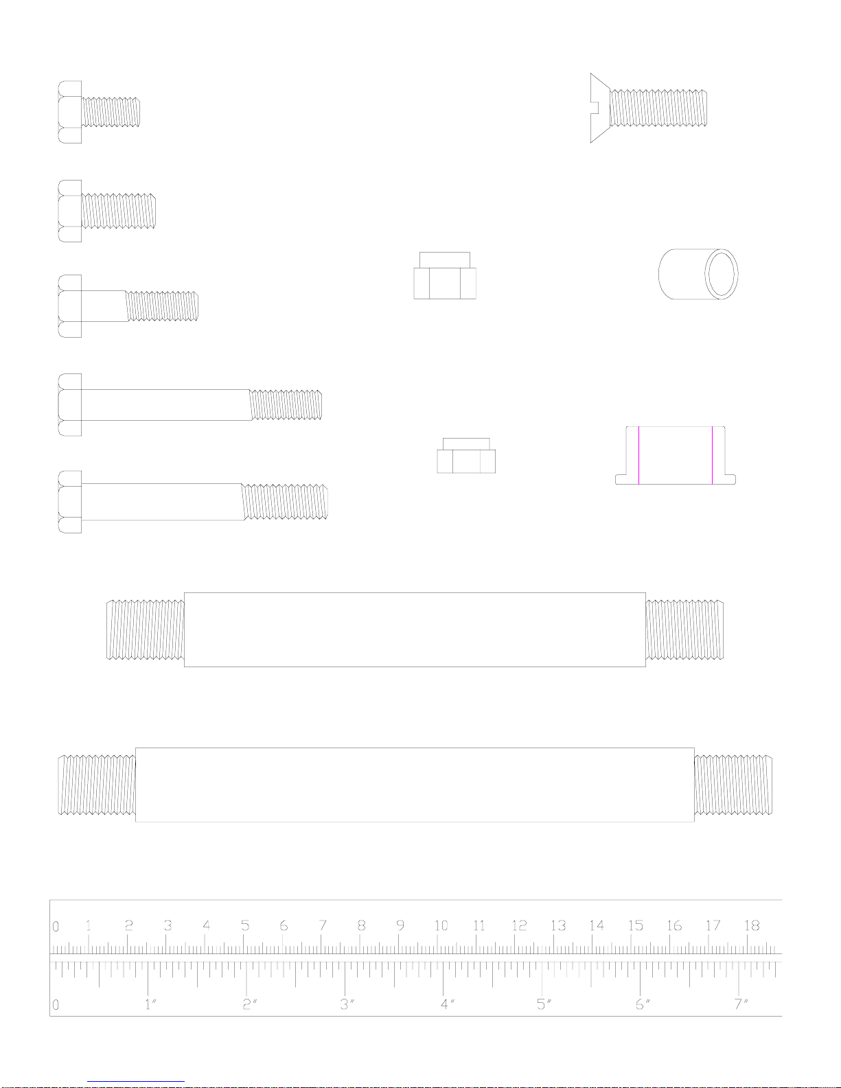
(67)3/8" LOCKNUT (46)13mm BUSHING
(70)3/4" BUSHING
(61)5/8"x7-3/4" SHAFT BAR
(60)5/8"x5-3/4" SHAFT BAR
mm
(48)M8X25 HEX BOLT
(53)3/8"x2-5/8" HEX BOLT
(52)M8X63 HEX BOLT
(50)3/8"x3/4" HEX BOLT
(49)M8X15 HEX BOLT
(69)M8mmLOCKNUT
(47)M10x25mm SCREW
Hardware Illustrations
Page 1

6
(59)3/8"x6-1/8" HEX BOLT
(58)3/8"x5-1/8" HEX BOLT
(57)3/8"x4-1/2" HEX BOLT
mm
(56)3/8"x3-1/2" HEX BOLT
(65)5/8" WASHER
(66)5/8" LOCKNUT
Hardware Illustrations
Page 2

7
(3)RIGHT
VERTICAL (5)LEFT VERTICAL
FRAME
(4)LEFT
OBLIQUE
FRAME
(2)RIGHT OBLIQUE
FRAME
(12)LEFT TOP
(20)RIGHT BENCH
PRESS
FRAME
(15)LEFT SEAT
CUSHION FRAME (16)CONNECTOR
(13)RIGHT SEAT
CUSHION
FRAME
(19)RIGHT PRESS
(11)RIGHT TOP
CROSS FRAME
(8)CENTER BASE
TUBE (B)
(1)RIGHT BASE
BEAM
(36)SHROUD(9)GUIDE ROD
(14) LEG EXTENSION
(10)TOP CROSS
FRAMEBEAM
(6)LEFT BASE TUBE (A)
(7)CENTER BASE
FRAME
FRAME TUBE
(17)FOAM ROD (18)SEAT
CUSHION (21) ADJUST
TUBE PLATE
(22)FOOT
CROSS FRAME
ARM
Parts Identification
Page 1

8
Parts Identification
Page 2
(23)LEG
PRESS
SUPPORT
(32)PIVOT PULLEY
BRACKET
(37)LAT BAR
(41)LEFT
BACKREST
CUSHION
(29)LEFT
ADJUSTABLE
PLATE
(33)LEFT BENCH
PRESS FRAME
(35)STOP ROD (42)WEIGHT
SELECTION
ROD(A)
(31)RIGHT
BACKREST
CUSHION
(34)LEFT PRESS
ARM
(28)RIGHT
BUTTERFLY ARM
(25)BUTTERFLY
EXTENSION
(30)LEFT
BUTTERFLY ARM
(39)DOUBLE
PULLEY
BRACKET(A)
(40)DOUBLE
PULLEY
BRACKET(B)
(24)SAFETY
CLASP (26)HANDLE
(38)CURL BAR
(27)RIGHT
ADJUSTABLE
PLATE
(43)WEIGHT
SELECTION
ROD(B)
(44)WAIST BAND

9
Parts Identification
Page 3
(74)1" ROUND
END PLUG
(86)HAND GRIPS
(68)SQUAT CABLE
(92)BUTTERFLY
CABLE
(75)2" ROUND
END PLUG
(91)CHAIN
(90)CHAIN
HOOK
(84) LONG FOAM
GRIPS
(71)2" SQUARE
END PLUG
(93)UPPER CABLE (94) LEG CABLE
(80)PRESS BAR PIN
(82)RUBBER
DONUT (83)FOAM ROLL
(76) PULLEY
(73)1"x2"
END PLUG
(81)2"SQUARE
RUBBER
BUMPER
(85)SHORT FOAM
GRIPS
(79)WEIGHT
(77)TOP PLATE
(72)2"
SQUARE
END CAP
(78)7/16"ALLEN
CAP SCREW
(87) BUSHING
PLASTIC(A) (88) BUSHING
PLASTIC(B) (89) POP PIN
(55)PRESS CABLE

10
Parts List
Item Q’ty PartName
1 1 Right Base Beam
2 1 Right Oblique Frame
3 1 Right Vertical Frame
4 1 Left Oblique Frame
5 1 Left Vertical Frame
6 1 Left Base Beam
7 1 Center Base Tube “A”
8 1 Center Base Tube “B”
9 4 GuideRod
10 1 Top Cross Frame
11 1 Right Top Cross Frame
12 1 Left Top Cross Frame
13 1 Right Seat Cushion Frame
14 1 Leg Extension Frame
15 1 Left Seat Cushion Frame
16 2 Connector Tube
17 2 Foam Rod
18 2 Seat Cushion
19 1 Right Press Arm
20 1 Right Bench Press Frame
21 1 Adjust Tube
22 1 Foot Plate
23 1 Leg Press Support
24 1 Safety Clasp
25 1 ButterflyExtension
26 2 Handle
27 1 RightAdjustablePlate
28 1 Right Butterfly Arm
29 1 LeftAdjustablePlate
30 1 Left Butterfly Arm
31 1 Right Backrest Cushion
32 2 Pivot Pulley Bracket
33 1 Left Bench Press Frame
34 1 Left Press Arm
35 1 Stop Rod
36 2 Shroud
37 1 Lat Bar
38 1 Curl Bar
39 1 Double Pulley Bracket “A”
40 1 Double Pulley Bracket “B”
41 1 Left Backrest Cushion
42 1 Weight Selection Rod “A”
43 1 Weight Selection Rod “B”
44 1 Waist Band
45 1 Ankle Strap
46 12 13mm Bushing
47 3 M10 x 25mm Screw
48 3 M8 x 25mm Hex Bolt
Item Q’ty PartName
49 8 M8 x 15mm Hex Bolt
50 18 3/8”x 3/4”Hex Bolt
51 15 3/8”x 2”Hex Bolt
52 4 M8 x 63mm Hex Bolt
53 7 3/8”x 2-5/8”Hex Bolt
54 25 3/8”x 3”Hex Bolt
55 1 Press Cable
56 3 3/8”x 3-1/2”Hex Bolt
57 5 3/8”x 4-1/2”Hex Bolt
58 1 3/8”x 5-1/8”Hex Bolt
59 1 3/8”x 6-1/8”Hex Bolt
60 1 5/8”x 5-3/4”Shaft Bar
61 1 5/8”x 7-3/4”Shaft Bar
62 150 3/8”Washer
63 2 3/8”Big Washer
64 22 M8 Washer
65 6 5/8”Washer
66 6 5/8”Locknut
67 66 3/8”Locknut
68 1 Squat Cable
69 5 M8Locknut
70 16 3/4”Copper Bushing
71 18 2”Square End Plug
72 4 2”Square End Cap
73 8 1”x 2”End Plug
74 10 1”Round End Plug
75 2 2”Round End Plug
76 32 Pulley
77 2 Top Plate
78 2 7/16”Allen Cap Screw
79 33 Weight
80 2 Press Bar Pin
81 3 2”Square Rubber Bumper
82 4 Rubber Donut
83 4 Foam Roll
84 2 Long Foam Grip
85 2 Short Foam Grip
86 6 HandGrip
87 4 Plastic Bushing “A”
88 2 Plastic Bushing “B”
89 2 Pop Pin
90 8 ChainHook
91 3 Chain
92 1 ButterflyCable
93 1 UpperCable
94 1 Leg Cable

11
NOTES

12
IMPORTANT
PLEASE READ ALL INSTRUCTIONS CAREFULLY BEFORE ASSEMBLING
FIGURE 1
Step 1.
Step 2.
Step 3.
Step 4.
Step 5.
Step 6.
Step 7.
Push 2”SQUARE END PLUGS (71) into ends of RIGHT BASE BEAM (1), LEFT BASE BEAM
(6),andLEFTOBLIQUE FRAME (4).
AttachCENTERBASE TUBE “A”(7) to RIGHTBASE BEAM (1) andLEFT BASE BEAM (6)with
3/8”x2-5/8”HEX BOLTS (53), 3/8”WASHERS(62)and3/8”LOCKNUTS (67).
NOTE: Donot tighten LOCKNUTS untilCENTER BASE TUBE“B”has been attached.
SlideRIGHTVERTICALFRAME(3)ontoRIGHTBASEBEAM (1)andattachwithCENTERBASE
TUBE“B”(8) using 3/8”x 3”HEX BOLTS (54), 3/8”WASHERS (62) and 3/8”LOCKNUTS (67).
SlideLEFT VERTICAL FRAME (5) onto LEFT BASE BEAM (6) and attach with CENTER BASE
TUBE“B”(8) using 3/8”x 3”HEX BOLTS (54), 3/8”WASHERS (62) and 3/8”LOCKNUTS (67).
Tighten3/8”LOCKNUTS(67)attachedin Step 2.
Attach RIGHT OBLIQUE FRAME (2) to RIGHT BASE BEAM (1) with 3/8”x 2-5/8”HEX BOLTS
(53),3/8”WASHERS(62) and 3/8”LOCKNUTS (67).
AttachLEFTOBLIQUEFRAME(4)to LEFT BASE BEAM (6) with 3/8”x2-5/8”HEXBOLTS(53),
3/8”WASHERS (62) and 3/8”LOCKNUTS (67).

13
FIGURE 1
3
RIGHT
VERTICAL
FRAME
71
2”SQUARE
ENDPLUG
54
3/8”x 3”
HEXBOLT
1
RIGHT
BASE
BEAM
5
LEFT
VERTICAL
FRAME
6
LEFT
BASE
BEAM
4
LEFT
OBLIQUE
FRAME
67
3/8”
LOCKNUT
7
CENTER
BASETUBE
(A)
62
3/8”
WASHER
53
3/8”x 2-5/8”
HEXBOLT
2
RIGHT
OBLIQUE
FRAME
8
CENTER
BASETUBE
(B)
71
2”SQUARE
ENDPLUG
71
2”SQUARE
ENDPLUG
71
2”SQUARE
ENDPLUG
62
3/8”
WASHER
67
3/8”
LOCKNUT
53
3/8”x 2-5/8”
HEXBOLT

14
FIGURE 2
8
CENTER
BASETUBE
(B)
Step 8.
Step 9.
Slide RUBBER DONUTS (82) onto one end of each GUIDE ROD (9) and insert into CENTER
BASE TUBE “B”(8).
Slideatotalof 14WEIGHTS(79),ONE AT A TIME,down GUIDERODS(9)ontheRIGHT BASE
BEAM(1)side, with SLOTonbottom and facing forwardas shown.
Slide the other 19 WEIGHTS (79),
ONE AT A TIME, down GUIDE
RODS(9)ontheLEFTBASE BEAM
(6) side, with SLOT on bottom and
facingforwardasshown.
InsertWEIGHTSELECTORROD“A”
(42) through center of 14 high
WEIGHT(79)stack.
InsertWEIGHTSELECTORROD“B”
(43) through center of 19 high
WEIGHT(79)stack.
WARNING: Someone will need to
hold this stack until Step 21 is com-
pleted.
Slide TOP PLATES (77) onto both
WEIGHT(79)stacks.
Fasten TOP PLATES (77) through
top hole of WEIGHT SELECTOR
RODS (42 & 43) with 7/16”ALLEN
CAP SCREW (78).
Thread PRESS CABLES (55) into
WEIGHT SELECTOR RODS (42 &
43).
InsertPRESS BAR PIN (80)into de-
sired SLOT in WEIGHTS (79) and
throughWEIGHTSELECTOR
RODS (42 & 43).
Step 10.
Step 11.
Step 12.
Step 13.
Step 14.
Step 15.
Step 16.
82
RUBBER
DONUT
9
GUIDE
ROD
1
RIGHT
BASE
BEAM
6
LEFTBASE
BEAM
77
TOP
PLATE
42
WEIGHT
SELECTOR
ROD
“A”
79
WEIGHT
(19 total)
SLOT
80
PRESS
BARPIN
FIGURE 2
80
PRESS
BARPIN
78
7/16”
ALLEN
CAP
SCREW
43
WEIGHT
SELECTOR
ROD
“B”
82
RUBBER
DONUT
79
WEIGHT
(14 total)
55
PRESS
CABLE
55
PRESS
CABLE

15
Step 17.
Step 18.
Step 19.
FIGURE 3
4
LEFT
OBLIQUE
FRAME
2
RIGHT
OBLIQUE
FRAME
67
3/8”
LOCKNUT
62
3/8”
WASHER
71
2”SQUARE
ENDPLUG
71
2”SQUARE
ENDPLUG
Push2”SQUAREENDPLUG(71)intoendofTOPCROSS FRAMES (11 RIGHT and 12 LEFT).
AttachRIGHTTOPCROSS FRAME (11) to RIGHTOBLIQUEFRAME(2)with3/8”x2-5/8”HEX
BOLTS(53), 3/8”WASHERS(62)and3/8”LOCKNUTS (67).
Attach LEFT TOP CROSS FRAME (12) to LEFT OBLIQUE FRAME (4) with 3/8”x 2-5/8”HEX
BOLTS(53), 3/8”WASHERS(62)and3/8”LOCKNUTS (67).
11
RIGHT TOP
CROSS
FRAME
12
LEFT TOP
CROSS
FRAME
53
3/8”x 2-5/8”
HEXBOLT
62
3/8”
WASHER
62
3/8”
WASHER
53
3/8”x 2-5/8”
HEXBOLT
62
3/8”
WASHER
FIGURE 3

16
Step 20.
Step 21.
Step 22.
FIGURE 4
Push 2”SQUARE END PLUGS (71) into each end of TOP CROSS FRAME (10).
PlaceTOPCROSS FRAME (10) into topofVERTICAL FRAMES (3 RIGHT &5LEFT) and over
GUIDERODS(9)with SHROUD BRACKETS facing front asshown.
Attach RIGHT TOP CROSS FRAME (11), LEFT TOP CROSS FRAME (4) and TOP CROSS
FRAME(10)toRIGHTVERTICALFRAME(3)and LEFT VERTICAL FRAME with 3/8”x 3”HEX
BOLTS(54),3/8”WASHERS(62) and 3/8”LOCKNUTS (67).
11
RIGHT TOP
CROSS
FRAME
10
TOP
CROSS
FRAME
SHROUD
BRACKET
71
2”SQUARE
ENDPLUG
3
RIGHT
VERTICAL
FRAME
5
LEFT
VERTICAL
FRAME
71
2”SQUARE
ENDPLUG
12
LEFT TOP
CROSS
FRAME
9
GUIDE
ROD
54
3/8”x 3”
HEXBOLT
54
3/8”x 3”
HEXBOLT
67
3/8”
LOCKNUT
62
3/8”
WASHER
67
3/8”
LOCKNUT
62
3/8”
WASHER
FIGURE 4

17
FIGURE 5
Step 23.
Step 24.
Step 25.
Attach2”SQUARERUBBERBUMPERS (81) toRIGHTSEATCUSHIONFRAME(13)withM10
x25mm SCREW (47).
AttachRIGHTSEAT CUSHION FRAME(13) to RIGHT OBLIQUEFRAME (2) with 3/8”x 2-5/8”
HEX BOLTS (53) 3/8”WASHERS (62) and 3/8”LOCKNUTS (67).
Attach SEAT CUSHION (18) to RIGHT SEAT CUSHION FRAME (13) with M8 x 15mm HEX
BOLTS (49) and M8 WASHERS (64).
81
2”
SQUARE
RUBBER
BUMPER
47
M10 x 25mm
SCREW
13
RIGHT
SEAT
CUSHION
FRAME
81
2”
SQUARE
RUBBER
BUMPER
2
RIGHT
OBLIQUE
FRAME
53
3/8”x 2-5/8”
HEXBOLT
62
3/8”
WASHER
67
3/8”
LOCKNUT
62
3/8”
WASHER
18
SEAT
CUSHION
49
M8 x 15mm
HEXBOLT
64
M8
WASHER
64
M8
WASHER
FIGURE 5

18
FIGURE 6
Step 26.
Step 27.
Step 28.
Step 29.
Step 30.
Push2”SQUARE END PLUGS (71) intoeach end of LEG EXTENSION FRAME (14).
AttachLEGEXTENSIONFRAME (14)toRIGHTSEATCUSHIONFRAME(13) with 3/8”x2-5/8”
HEXBOLT (53), 3/8”WASHER (62) and3/8”LOCKNUT (67).
PlaceaPULLEY(76)intoSLOT in LEG EXTENSION FRAME(14)andfastenwith3/8”x2”HEX
BOLTS(51),3/8”WASHERS(62),13mm BUSHINGS (46) and3/8”LOCKNUTS(67).
Push1”ROUND END PLUGS (74) into ends of FOAM RODS (17).
NOTE: Liquid soap applied to FOAM RODS (17) will help FOAM ROLLS (83) slide on easier.
Slide one FOAM ROLL onto one end of FOAM ROD, insert one FOAM ROD through RIGHT
SEAT CUSHION FRAME (13) and the other through the LEG EXTENSION FRAME (14) and
slideotherFOAMROLL onto other end.
53
3/8”x 2-5/8”
HEXBOLT
71
2”
SQUARE
ENDPLUG
67
3/8”
LOCKNUT
14
LEG
EXTENSION
FRAME
76
PULLEY
62
3/8”
WASHER
13
RIGHT
SEAT
CUSHION
FRAME
71
2”
SQUARE
ENDPLUG
62
3/8”
WASHER
67
3/8”
LOCKNUT
46
13mm
BUSHING
74
1”
ROUND
ENDPLUG
62
3/8”
WASHER
74
1”
ROUND
ENDPLUG
SLOT
51
3/8”x 2”
HEXBOLT
17
FOAM
ROD
83
FOAM
ROLL
74
1”
ROUND
ENDPLUG
83
FOAM
ROLL
83
FOAM
ROLL
83
FOAM
ROLL
17
FOAM
ROD
FIGURE 6

19
FIGURE 7
Step 31.
Step 32.
Step 33.
Step 34.
Step 35.
Attach2”SQUARERUBBER BUMPER (81) toLEFT SEAT CUSHIONFRAME(15) with M10 x
25mm SCREW (47).
Attach LEFT SEAT CUSHION FRAME (15) to LEFT OBLIQUE FRAME (4) with 3/8”x 2-5/8”
HEX BOLTS (53) 3/8”WASHERS (62) and 3/8”LOCKNUTS (67).
AttachSEATCUSHION(18)toLEFTSEATCUSHIONFRAME(15)withM8x15mmHEXBOLTS
(49)and M8 WASHERS(64).
Push1-3/8”x 2”END CAP (72) into ends ofCONNECTOR TUBES (16).
AttachCONNECTORTUBES(16)toLEFT SEAT CUSHIONFRAME (15)
and LEFT BASE BEAM (6) with 3/8”x 4-1/2”HEX BOLTS (57),
3/8”WASHERS (62) and 3/8”LOCKNUTS (67).
81
2”
SQUARE
RUBBER
BUMPER
47
M10 x 25mm
SCREW
67
3/8”
LOCKNUT
62
3/8”
WASHER
18
SEAT
CUSHION
49
M8 x 15mm
HEXBOLT
64
M8
WASHER
53
3/8”x 2-5/8”
HEXBOLT
4
LEFT
OBLIQUE
FRAME
15
LEFT
SEAT
CUSHION
FRAME
73
1”x 2”
ENDPLUG
16
CONNECTOR
TUBE
6
LEFTBASE
BEAM
57
3/8”x 4-1/2”
HEXBOLT
67
3/8”
LOCKNUT
62
3/8”
WASHER
62
3/8”
WASHER
62
3/8”
WASHER
FIGURE 7 73
1”x 2”
ENDPLUG
73
1”x 2”
ENDPLUG
73
1”x 2”
ENDPLUG
16
CONNECTOR
TUBE

20
FIGURE 8
Step 36.
Step 37.
Step 38.
Step 39.
Step 40.
Step 41.
Step 42.
Attach RIGHT BACKREST CUSHION (31) to RIGHT OBLIQUE FRAME (2) with 3/8”x 2-5/8”
HEX BOLTS (53) and 3/8”WASHERS (62).
Push3/4”BUSHINGS(70)intoRIGHT BENCH PRESS FRAME (20).
AttachPULLEY(76) toRIGHTBENCHPRESSFRAME (20)with3/8”x6-1/8”HEXBOLT(59),3/
8”WASHERS (62) and3/8”LOCKNUT (67).
AttachRIGHTBENCHPRESS FRAME(20)toRIGHTBASEBEAM(1) with 5/8”x7-3/4”SHAFT
BAR(61), 5/8”WASHERS(65) and 5/8”LOCKNUTS(66).
Attach RIGHT PRESS ARM (19) to RIGHT BENCH PRESS FRAME (20) with 3/8”x 3”HEX
BOLTS(54), 3/8”WASHERS(62) and 3/8”LOCKNUTS (67).
Push1”ROUNDENDPLUGS(74)intoendsofRIGHTPRESSARM(19)andslide 2”SQUARE
END CAPS (72) over ends.
NOTE: LiquidsoapappliedtoRIGHTPRESSARM(19)willhelp LONG FOAM GRIPS (84) slide
oneasier.
SlideLONGFOAMGRIPSontoendsofRIGHTPRESSARM(19)untilflushwith end.
Table of contents
Other Fitness Quest Home Gym manuals