Flamerite Fires E-FX 1000 User manual

1
Installation, Precautions & Servicing
This product is only suitable for well insulated spaces or occasional use
1000
1300
1500
1800
www.e-fxfires.com
2
Important
Carefully remove the fire from the packing checking neither the heater nor the power cable has been
damaged during transport. Do not operate the fire if damaged.
Please bear in mind the weight of the fire before removal from the packaging and installation.
Consider if help is required.
The accessories are found in a box that is packed at the side of the fire.
Always read this manual first before attempting to install or use and keep in a safe place.
Your fire is guaranteed for three years from the date of purchase.
Important Safety Information and Warnings 3
UCKA Declaration 4
Technical Specification 4
Installation Instructions 5
Rear Glass Removal 8
Fuel Effects 10
Glass Fitting & Removal 10
Information Requirements 12
Trouble Shooting 13
Wiring Diagrams 14
Recycling
Contents
Registration No WEE/DH1656ZW
In accordance with European Directive 2012/19/ EU, waste
electrical and electronic equipment (WEEE) must not be disposed
of with household waste.
Please recycle responsibly.
EN

3
•WARNING: In order to avoid overheating, do not cover the heater.
•For indoor use only.
•Do not use the fire in the vicinity of a bath, shower or swimming pool.
•Never use the fire to dry laundry.
•The heater must not be located immediately below a socket outlet.
•The use of an extension lead is not recommended.
•This appliance can be used by children aged from 8 years and above and persons with reduced
physical, sensory or mental capabilities or lack of experience and knowledge if they have been given
supervision or instruction concerning use of the appliance in a safe way and understand the hazards
involved. Children shall not play with the appliance. Cleaning and user maintenance shall not be
made by children without supervision.
•Children of less than 3 years should be kept away unless continuously supervised
•Children aged from 3 years and less than 8 years shall only switch on/off the appliance provided
that it has been placed or installed in its intended normal operating position and they have been
given supervision or instruction concerning use of the appliance in a safe way and understand the
hazards involved.
•Children aged from 3 years and less than 8 years shall not plug in, regulate and clean the appliance
or perform user maintenance.
•Some parts of this product can become very hot and cause burns. Particular attention must be
given where children and vulnerable people are present
•Caution should be applied to ensure that children do not play with the fuel effects.
•As with any electrical appliance whilst the instructions aim to cover as many eventualities as
possible, caution and common sense should be applied when operating your appliance, particularly
in the vicinity of small children.
•CAUTION: The heater is fitted with an automatic cut out to prevent any damage due to
overheating. The element will continually and automatically cut out if the airflow is obstructed.
Never cover the air outlets. To reset, switch the fire off, disconnect from the mains supply, remove
the cause of the overheating. Allow to cool for a suitable period then switch the fire back on.
•CAUTION: In order to avoid a hazard due to inadvertent resetting of the thermal cut out, the
appliance must not be supplied through an external switching device, such as a timer, or connected
to a circuit regularly switched on and off by a utility.
Important Safety Information and Warnings
Where a chimney is not blocked off completely, any draw will cause the heater to cut
out during use. Care should also be taken when fitting into a cavity wall in case of
damp or draft with external air vents fully sealed
4
Trade name: E-FX
Ratings: 220-240 Vac, 50Hz Class 1
Product Type: Electric Fire (fan heater)
Requirements:
BS-EN 60335-2-30:2009 + A11:2012
BS-EN 60335-1:2012 + A11:2014 + A13:2017 + A1:2019 + A14:2019 + A2:2019
BS-EN 55014-1:2017
BS-EN 55014-2:2015
BS-EN61000-3-2:2014
BS-EN 61000-3-3:2013
Manufactured by: Flamerite Fires Ltd. Greenhough Road, Lichfield. Staffs. WS13 7AU. UK
A 230V 13A 50Hz supply is required.
Maximum power consumption: 1500 Watts
A 1.8 metre lead with a BS1363 plug containing a BS1362 13A fuse is supplied. Only use a BS1362 13A fuse
with this appliance.
Minimum opening to fit and inset the fire
Model
H
W1side
W2side
W3side
D
1000
575mm
1045mm
1025mm
1010mm
285mm
1300
575mm
1345mm
1325mm
1310mm
285mm
1500
575mm
1545mm
1525mm
1510mm
285mm
1800
575mm
1845mm
1825mm
1810mm
285mm
Visible burn area after fitting
Model
H
W1side
W2side
W3side
D2/3 side
1000
350mm
1045mm
1025mm
1000mm
180mm
1300
350mm
1345mm
1325mm
1300mm
180mm
1500
350mm
1545mm
1525mm
1500mm
180mm
1800
350mm
1845mm
1825mm
1800mm
180mm
Technical Specification
UKCA Declaration
5
WARNING: DO NOT TWIST, FORCE OR SQUEEZE THE FIRE DURING THE INSTALLATION PROCESS.
There must be enough clearance for the fire to comfortably fit inside or against a wall. DO NOT SQUEEZE
INTO AN OPENING as this may deform the case and stop the glass from moving correctly.
The fire must be well supported in or on any structure. A wall support or lintel should be fitted at the
required height to ensure the appliance does not support the weight of the finished wall or chimney
breast. Never secure to just plaster board alone.
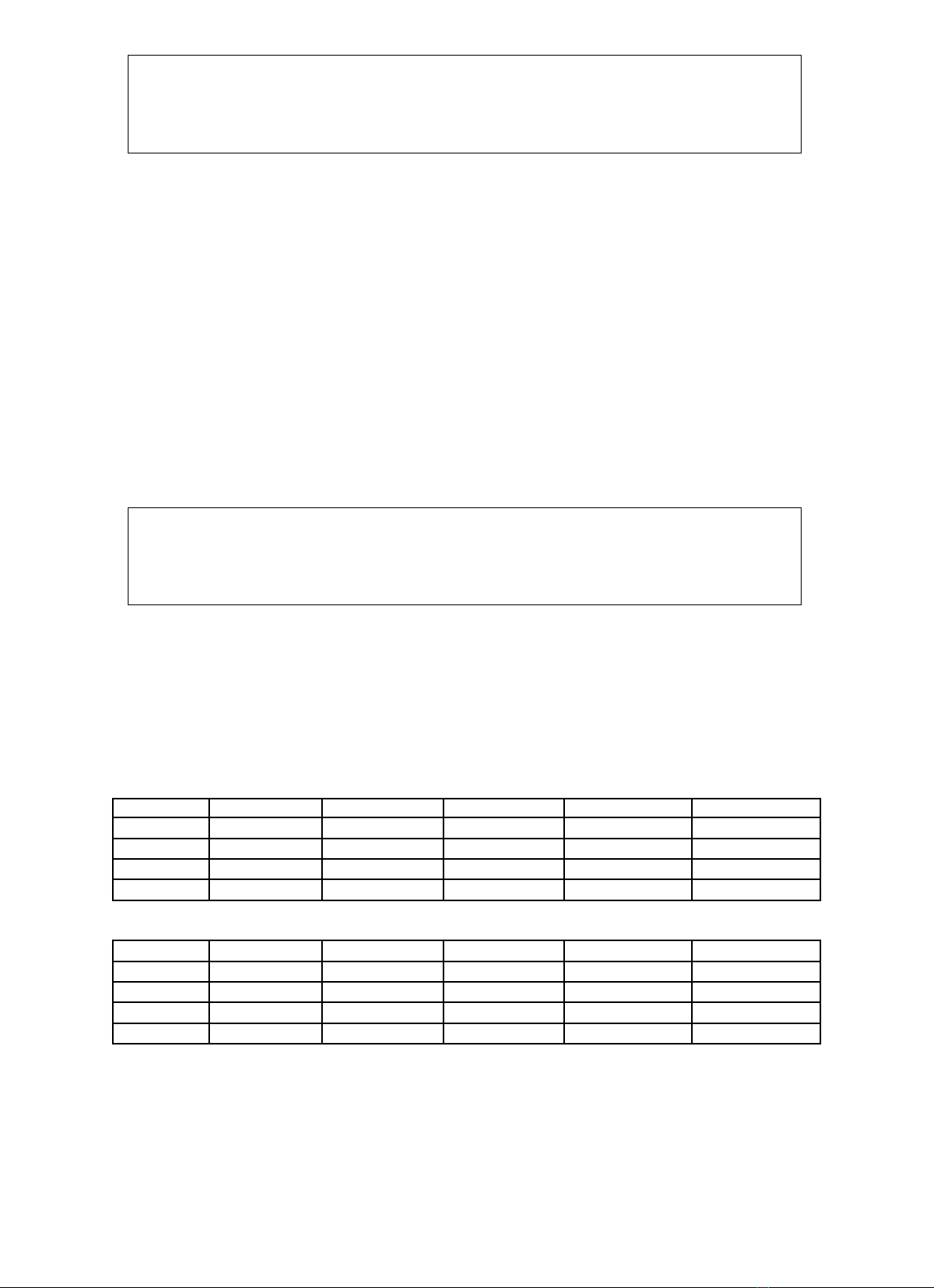
E-FX Side panels for 1 or 2 sided corner fitting.
If fitting as a 1 or 2 sided corner fire, blanking panels will need to be fitted. Each blanking panel consists of
two parts fitted directly over the side glass. If you need to fit the blanking panel(s) follow the instructions
and images below.
•The right side blanking panel is shown above as you look at the fire.
•Place together as though you have formed a tray with an edge/return on each of the four sides
•Slide onto the fire so the forward edge/return of the inner panel touches the glass panel edge.
•Fix using the four screws, two on the top and bottom but make sure the inner panel and the glass
have free movement to slide forwards and backwards.
Installation Instructions
6
Fitting E-FX Fire onto a wall or into a structure.
If purchased as a fire only or as a standard wall mount suite, the height at which you may wish to fix the
fire in or on the wall is up to you.
When purchased as part of a E-FX Media Wall, refer to those instructions. If purchased with a Plinth or
Contemporary legs, the height you will need to fit the top of the lower fire bracket to the floor is in the
table below.
Product
Standard
Contemporary Legs
Plinth
E-FX 1000
N/A
230mm
255mm
E-FX 1300
N/A
230mm
255mm
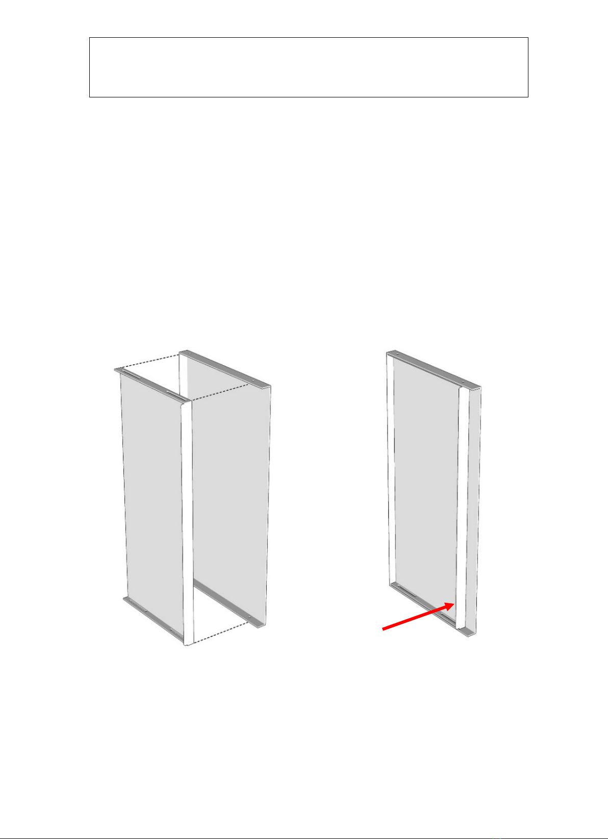
Take the following steps securing your fire firmly into position and onto a wall. Both top and lower fixing
brackets come already attached to the fire. The lower bracket will have to be removed to begin the
process.
Lower Bracket
Fixings
1000
1300
1500
1800
60mm screws
4
4
4
4
M10 rawl plugs
4
4
4
4
M6 bolts
2
2
2
2
M6 washers
2
2
2
2
Remove the bolts and washers (remove the lower bracket only). Mark up and drill the holes with an M10
bit and fit the rawl plugs. Using the screws, secure the bracket to the wall.
7
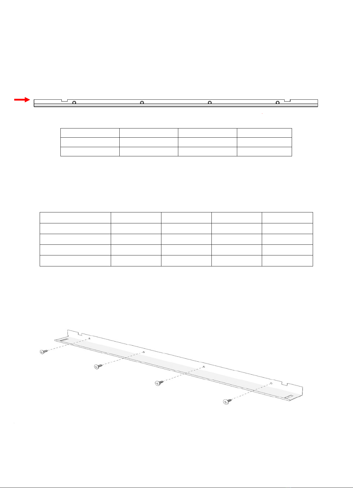
Top Bracket
Fixings
1000
1300
1500
1800
60mm screws
3
3
3
4
M10 rawl plugs
3
3
3
4
13mm screws
4
4
4
4
A second person will be required. For now, leave the top bracket attached. Place and hold the fire on the
lower bracket and refit the bolts and washers through the slots back into the fire. Keeping the fire firmly
pushed against the wall, mark across the length of the top bracket and into the slots above each hole. Once
again remove the bolt and washers and place the fire onto the floor.
Remove the screws and top bracket from the fire. Using it as a template mark the fixing holes on the wall,
drill the holes with an M10 bit and fit the rawl plugs. Using the 60mm screws fix the bracket to the wall.
Secure the fire onto the brackets
Place and hold the fire on the lower bracket and screw the top bracket back onto the fire with the self-
tappers. At this point you will be able to level the fire accordingly when refitting the M6 bolts and washers
through the slots of the lower bracket and back into the fire.

8
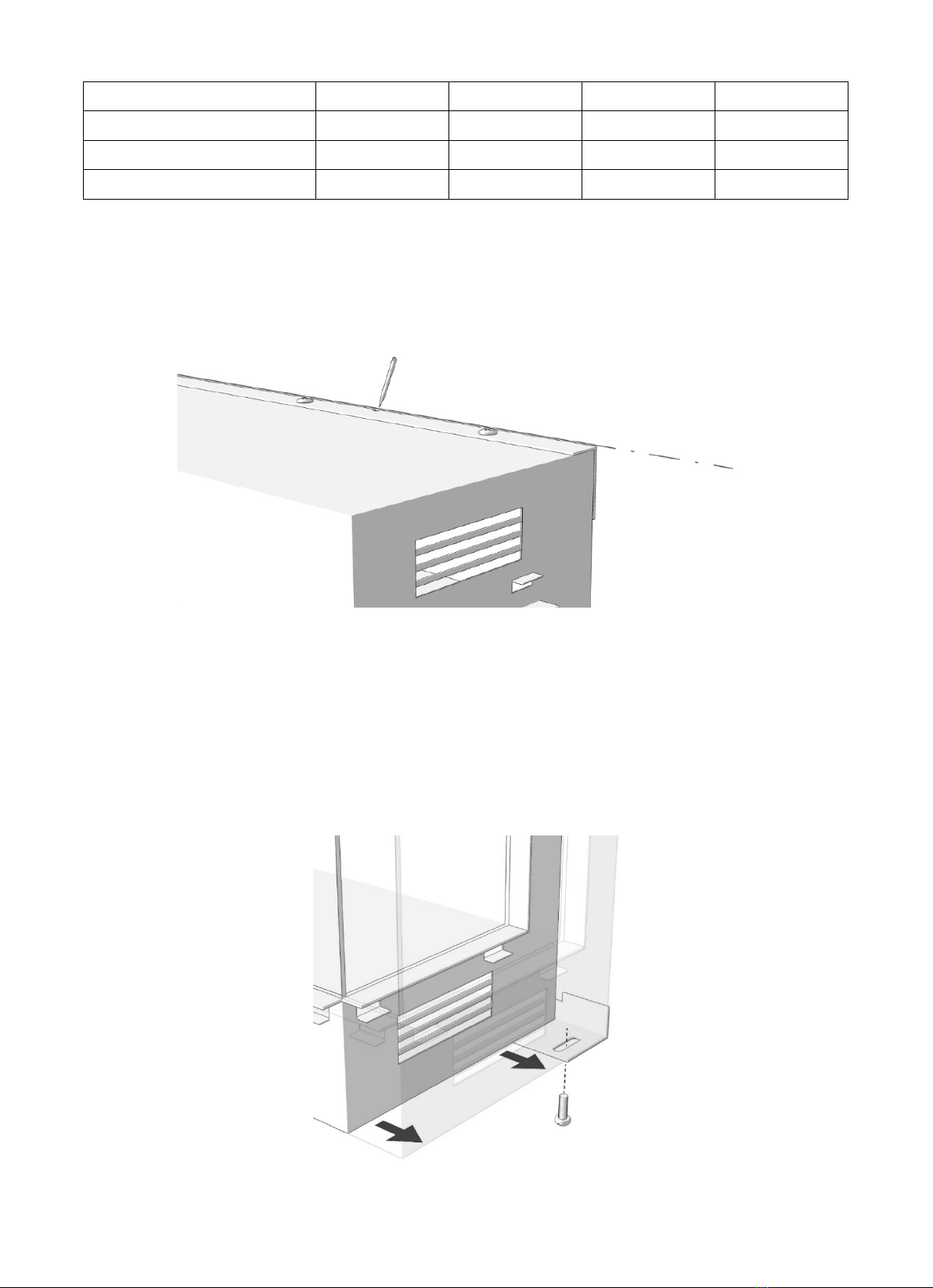
Before any further work is completed now your fire is secure, make sure the mains cable is tightly fitted
underneath the fire.
As standard one of the two rear screens in the fire has a reflective coating to mirror the log effect. When
the fire is on, the flame simulates a 3 dimensional burn between the actual log effect and the refection
generated by the coating. If your preference is non-reflective, the glass with the reflective coating can be
removed leaving only the projection screen in place.
WARNING: Before any maintenance is undertaken, always disconnect
the fire from the mains power supply.
To remove the fuel bed, remove the two screws at either side. Gently lift the right side, you will need to
disconnect a cable from it to the circuit board below the connector marked Aon the top of the fuel bed.
Once this is done, you may now carefully remove the fuel bed.
Non Refective Rear Screen Option

9
You will need to carefully remove both screens, to do this unscrew the top bracket holding them in place.
Using the foam tape provided in the accessory pack, apply across the length of the top bracket’s front face
to keep the projection screen secure now the reflective glass screen has been removed. Screw the top
bracket back into place and add the projection screen. Place the fuel bed back into the fire, reconnect the
cable A underneath and replace both the screws at either side.
10
WARNING: DC SUPPLY 12V
IMPORTANT: FUEL EFFETCS MUST BE POSITIONED ACCORDING TO THE E-FX LOG INSTRUCTION BOOKLET.
CARE MUST BE TAKEN TO ENSURE THE CHANNEL AT THE AT THE FRONT OF THE FIRE IS NOT
OBSTRUCTED. ANYTHING DROPPED IN DURING FITTING OF THE FUEL EFFECTS, MUST BE REMOVED
BEFORE INSTALLING THE FRONT GLASS PANEL.
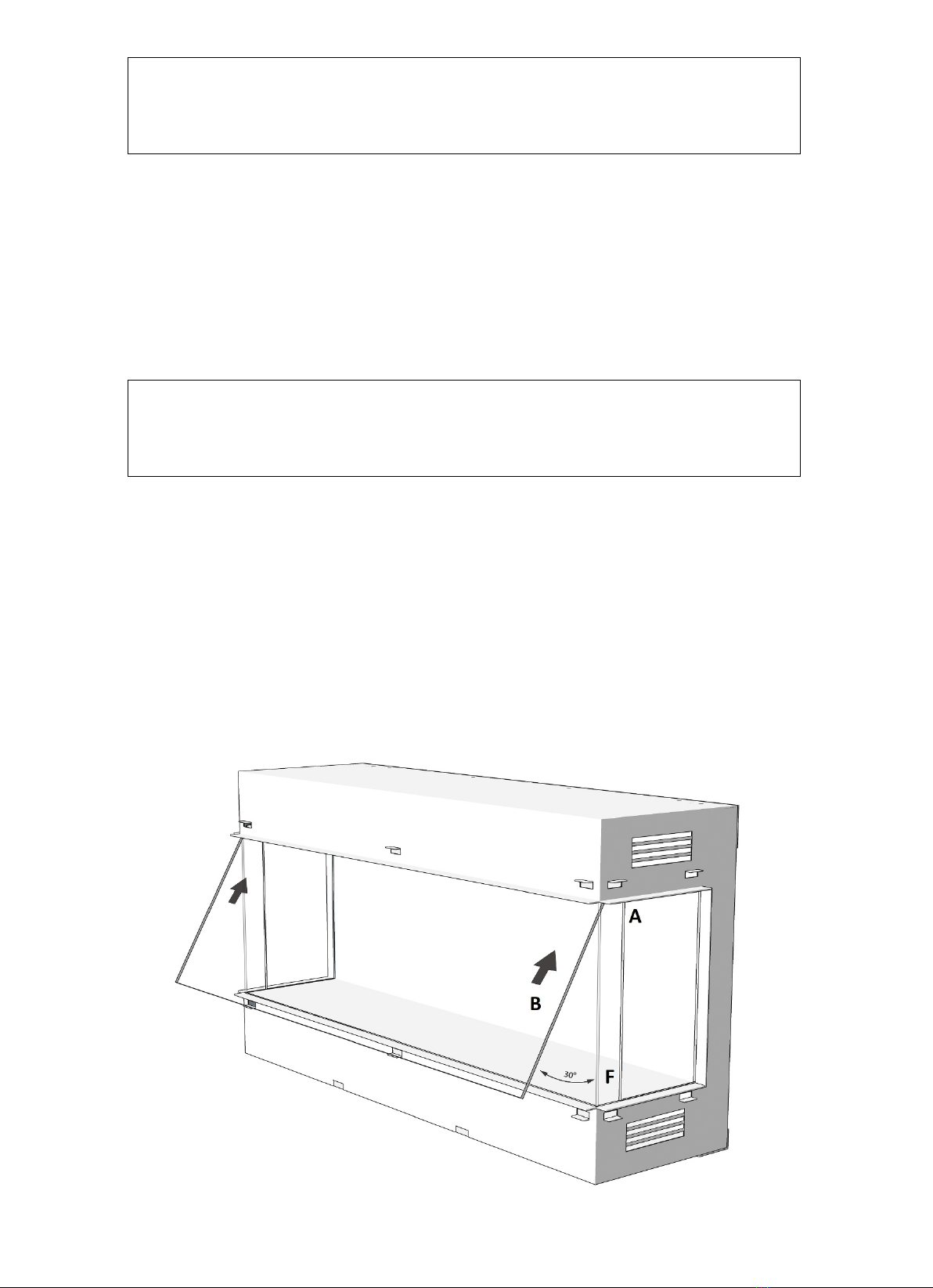
We recommend two persons to fit the EFX 1500 & 1800 glass
Fitting the front glass
Using the images below, push the side glass (A) back towards the rear of the case. You will notice a long
gap on the underside of the opening in front of the heater grills. At an angle of approximately 30 degrees,
push the glass up into this void (B) then straighten making sure the bottom of the glass clears the lower
edge of the fire opening. Carefully lower into the large channel that runs across the front avoiding the
dampers (C)
Fuel Effects
Glass Fitting & Removal

11
Place the handle (D) onto the top right-hand side of the glass. The upper glass rail is magnetic and will
easily fix into place along the top of the opening (E). Adjust the position of the handle (D) to fit into the
gap on the rail.
With the front glass tilted rearwards pull the side glass forwards (F). To open and close the front glass
panel, place your index finger on the handle as shown in the picture (G). You may finely position the front
and side glass panels to give the best possible fit and finish. Make sure the glass glides forwards and
backwards with ease.
The glass can be cleaned with a soft cloth and non-abrasive cleaner
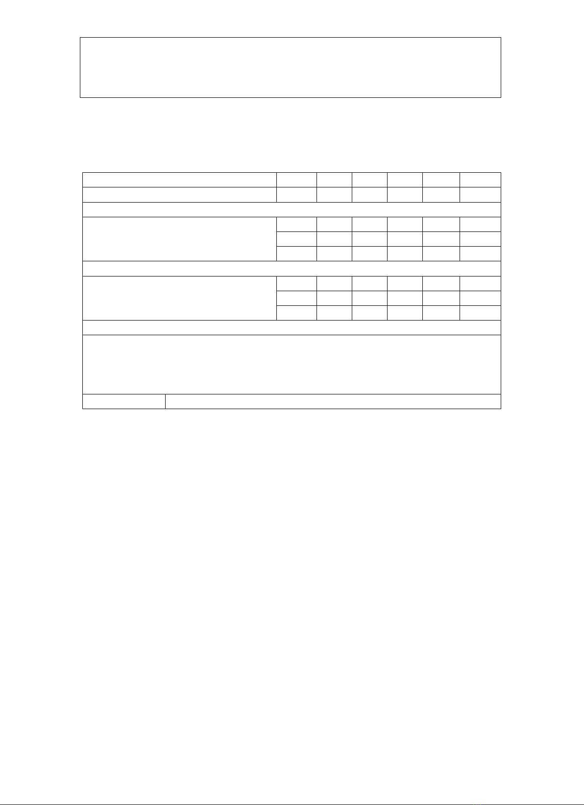
12
Information requirement for electric local space heaters
Model identifier (s)
1000
1300
1500
1800
Item@ 240v 50hz
Symbol
Value
Value
Value
Value
Unit
Heat output
Nominal heat output
Minimum heat output(indicative)
Maximum continuous heat output
Pnon
1.5
1.5
1.5
1.5
kW
Pmin
0.75
0.75
0.75
0.75
kW
Pmax,c
1.5
1.5
1.5
1.5
kW
Auxiliary electricity consumption
At normal heat
At minimum heat
In stand by
elmax
0.0312
0.0423
0.0437
0.0558
kW
elmin
0.0312
0.0423
0.0437
0.0558
kW
elSB
0.0005
0.0005
0.005
0.0005
kW
Type of heat output/ room temperature control
With distance control option Yes
Room temperature control, with open window detection Yes
Adaptive Start Yes
With electronic room temperature control plus week timer Yes
Contact Details:
Flamerite Fires Ltd. WS13 7AU. UK. www.flameritefires.com
Information Requirements

13
WARNING: Before any maintenance is undertaken, always disconnect
the fire from the mains power supply.
Maintenance must be undertaken by a Flamerite service engineer or similarly qualified persons in order to
avoid a hazard. Replacements part are available from www.flameritefires.com
PROBLEM
POSSIBLE CAUSE
SOLUTION
No power to the fire
Mains cable into the fire
Check the lead is securely plugged
into the bottom of the fire
Circuit Board
Replacement Circuit Board maybe
required
Mains wall socket
Check the socket is switched on
Fuse
Check fuses; in the mains plug and
in the fire, located next to the
On/Off switch
No lighting or illumination
Dimmer
Check dimmer range settings
LED
Replacement LED maybe required
Flame illuminated without
movement
Spindle
Check spindle is securely attached
to the motor
Motor
Replacement motor maybe
required
Logs not fully illuminated across
the fire
Log wiring & connectors
Remove glass; check each log is
tightly connected together
Log
Replacement Log maybe required
Fuel bed
Replacement LED maybe required
Heater blowing cold air
The safety cut out may have
operated
Check for obstruction around the
heater. If continually a problem
and fitted into a cavity wall or
chimney breast, check with
installer that the opening has
been 100% fully sealed from
drawn air and draft
Heat turns off quickly after
turning on
Thermostat setting too low
Set thermostat to a higher
temperature
Remote Control non responsive
Lost RF connection to fire
Turn fire off & on using the rocker
switch next to keypad
Batteries
Replace with 2 x AAA
Front glass will not glide freely
Debris from fuel bed in channel
Remove
Fitted incorrectly
Refer to; Installation Instructions
Maintenance & Trouble Shooting

14
Wiring Diagrams
Other manuals for E-FX 1000
1
This manual suits for next models
3
Popular Electric Heater manuals by other brands

EUROM
EUROM Alutherm Sani Verre 800 user manual

Chromalox
Chromalox PM400-2 installation instructions

NARVI
NARVI NC ELECTRIC 900513 Installation and instruction manual

Sawo
Sawo HEATERKING ROUND DRFT5-80Ni manual

EWT
EWT Leather LTH20LE instructions

Heatscope
Heatscope MHS-PE3000 Original installation and instruction manual

EUROM
EUROM Alutherm White 400 XS Wi-Fi user manual

Airchaud Diffusion
Airchaud Diffusion Haverland HL WI9S/C Instruction and installation manual
Radialight
Radialight ICON Wi-Fi operating instructions

Goldair
Goldair GIR350 operating instructions

RedCore
RedCore 15201-15203 user manual

Sawotec
Sawotec SAVONIA Series manual


