Fleck 2900S User manual

Model 2900s
Service Manual
IMPORTANT: Fill in Pertinent Information on Page 3 for Future Reference

Job Specification Sheet...................................................................................................................................................3
Installation Instructions....................................................................................................................................................4
3200 Timer Setting Procedure.........................................................................................................................................5
3210 & 3220 Timer Settings ............................................................................................................................................6
3200, 3210, 3220, & 3230 Regeneration Cycle Setting Procedure.................................................................................7
3200 Time Clock Timer Assembly ...................................................................................................................................8
3210 Meter Delayed Timer Assembly............................................................................................................................10
3220 Meter Immediate Timer Assembly ........................................................................................................................12
3230 Remote Start Timer Assembly..............................................................................................................................14
Upper Designer Powerhead Assembly..........................................................................................................................16
Lower Designer Powerhead Assembly..........................................................................................................................18
Upper Environmental Powerhead Assembly .................................................................................................................20
Lower Environmental Powerhead Assembly .................................................................................................................22
Control Valve Assembly.................................................................................................................................................24
Control Valve Side Mount Adapter.................................................................................................................................26
1600 Brine System ........................................................................................................................................................27
1650 Brine System Assembly........................................................................................................................................28
1700 Brine System Assembly........................................................................................................................................30
1710 Brine System Assembly........................................................................................................................................32
2” Brass Meter Assembly...............................................................................................................................................33
2” Plastic Meter Assembly .............................................................................................................................................34
1600 Service Valve Operator Assembly (Old Style) ......................................................................................................35
1600 Service Valve Operator (New Style) .....................................................................................................................36
2300 Safety Brine Valve ................................................................................................................................................37
2310 Safety Brine Valve ................................................................................................................................................38
2350 Safety Brine Valve Assembly................................................................................................................................39
Troubleshooting.............................................................................................................................................................40
Water Conditioner Flow Diagrams - Downflow..............................................................................................................42
Water Conditioner Flow Diagrams - Upflow ..................................................................................................................44
Flow Data & Injector Draw Rates - Downflow................................................................................................................46
Environmental Backplate Line Drawing.........................................................................................................................52
Designer Backplate Line Drawing .................................................................................................................................53
Plumbing Diagrams .......................................................................................................................................................54
Wiring Diagrams............................................................................................................................................................58
1600/1700 System Nozzle & Throat Chart....................................................................................................................62
Service Assemblies .......................................................................................................................................................63
Table of Contents
IMPORTANT PLEASE READ:
The information, specifications and illustrations in this manual are based on the latest information available at the time of•
printing. The manufacturer reserves the right to make changes at any time without notice.
This manual is intended as a guide for service of the valve only. System installation requires information from a number of•
suppliers not known at the time of manufacture. This product should be installed by a plumbing professional.
This unit is designed to be installed on potable water systems only.•
This product must be installed in compliance with all state and municipal plumbing and electrical codes. Permits may be•
required at the time of installation.
If daytime operating pressure exceeds 80 psi, nighttime pressures may exceed pressure limits. A pressure reducing valve must•
be installed.
Do not install the unit where temperatures may drop below 32°F (0°C) or above 125°F (52°C).•
Do not place the unit in direct sunlight. Black units will absorb radiant heat increasing internal temperatures.•
Do not strike the valve or any of the components.•
Warranty of this product extends to manufacturing defects of the vessel and controller, not the membrane. Misapplication of this•
product may result in failure to properly condition water, or damage to product.
A prefilter should be used on installations in which free solids are present.•
In some applications local municipalities treat water with Chloramines. High Chloramine levels may damage valve components.•
Correct and constant voltage must be supplied to the control valve to maintain proper function.•

Job Specification Sheet
Job Number: __________________
Model Number: ________________
Water Hardness: ___________________ ppm or gpg
Capacity Per Unit: ______________
Mineral Tank Size: ___________ Diameter: ___________ Height:
Salt Setting per Regeneration: _____________________________________________
1. Type of Timer:
A. 7 Day or 12 Day B. Meter Initiated
2. Downflow: Upflow Upflow Variable
3. Meter Size:
A. 3/4” Std Range (125 - 2,100 gallon setting)
B. 3/4” Ext Range (625 - 10,625 gallon setting)
C. 1” Std Range (310 - 5,270 gallon setting)
D. 1” Ext Range (1,150 - 26,350 gallon setting)
E. 1-1/2” Std Range (625 - 10,625 gallon setting)
F. 1-1/2” Ext Range (3,125 - 53,125 gallon setting)
G. 2” Std Range (1,250 - 21,250 gallon setting)
H. 2” Ext Range (6,250 - 106,250 gallon setting)
I. 3” Std Range (3,750 - 63,750 gallon setting)
J. 3” Ext Range (18,750 - 318,750 gallon setting)
K. Electronic________ Pulse Count ________ Meter Size
4. System Type:
A. System #4: 1 Tank, 1 Meter, Immediate, or Delayed Regeneration
B. System #4: Time Clock
C. System #4: Twin Tank
D. System #5: 2-5 Tanks, 2 Meters, Interlock
E. System #6: 2-5 Tanks, 1 Meter, Series Regeneration
F. System #7: 2-5 Tanks, 1 Meter, Alternating
G. System #9: Electronic Only, 2-4 Tanks, Meter per Valve, Alternating
H. System #14: Electronic Only, 2-4 Tanks, Meter per Valve. Brings units on and offline based on flow.
5. Timer Program Settings:
A. Backwash: ______________________ Minutes
B. Brine and Slow Rinse: _____________ Minutes
C. Rapid Rinse: ____________________ Minutes
D. Brine Tank Refill: _________________ Minutes
E. Pause Time: ____________________ Minutes
F. Second Backwash: _______________ Minutes
6. Drain Line Flow Control: ____________ gpm
7. Brine Line Flow Controller: __________________ gpm
8. Injector Size#: _____________________
9. Piston Type:
A. Hard Water Bypass
B. No Hard Water Bypass
Page 4
Installation Instructions
WATER PRESSURE: A minimum of 20 pounds (1.4 bar) of water pressure is required for regeneration valve to operate
effectively.
ELECTRICAL FACILITIES: An uninterrupted alternating current (A/C) supply is required. Note: Other voltages are
available. Please make sure your voltage supply is compatible with your unit before installation.
EXISTING PLUMBING: Condition of existing plumbing should be free from lime and iron buildup. Piping that is built
up heavily with lime and/or iron should be replaced. If piping is clogged with iron, a separate iron filter unit should be
installed ahead of the water softener.
LOCATION OF SOFTENER AND DRAIN: The softener should be located close to a drain to prevent air breaks and
back flow.
BY-PASS VALVES: Always provide for the installation of a by-pass valve if unit is not equipped with one.
CAUTION: Water pressure is not to exceed 125 psi (8.6 bar), water temperature is not to exceed 110°F (43°C), and the
unit cannot be subjected to freezing conditions.
Installation Instructions
Place the softener tank where you want to install the unit making sure the unit is level and on a firm base.1.
During cold weather, the installer should warm the valve to room temperature before operating.2.
All plumbing should be done in accordance with local plumbing codes. The pipe size for residential drain line should3.
be a minimum of 1/2” (13 mm). Backwash flow rates in excess of 7 gpm (26.5 Lpm) or length in excess of 20’
(6 m) require 3/4” (19 mm) drain line. Commercial drain lines should be the same size as the drain line flow control.
Refer to the dimensional drawing for cutting height of the distributor tube. If there is no4.
dimensional drawing, cut the distributor tube flush with the top of the tank.
Lubricate the distributor O-ring seal and tank O-ring seal. Place the main control valve on5.
tank. Note: Only use silicone lubricant.
Solder joints near the drain must be done prior to connecting the Drain Line Flow Control6.
fitting (DLFC). Leave at least 6” (15 cm) between the DLFC and solder joints when
soldering pipes that are connected on the DLFC. Failure to do this could cause interior
damage to the DLFC.
Teflon tape is the only sealant to be used on the drain fitting. The drain from twin tank units7.
may be run through a common line.
Make sure that the floor is clean beneath the salt storage tank and that it is level.8.
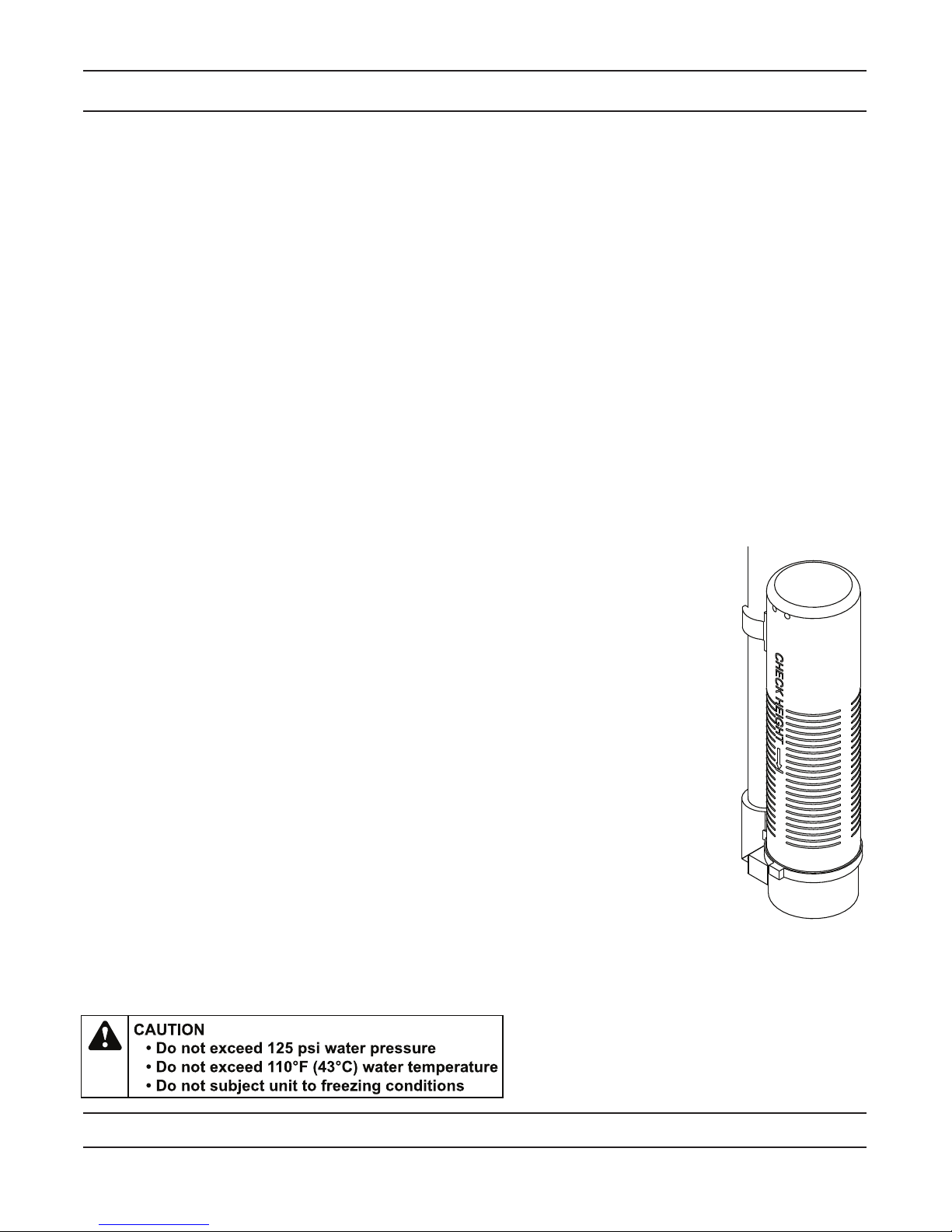
Place approximately 1” (25 mm) of water above the grid plate. If a grid is not utilized, fill to9.
the top of the air check (Figure 1) in the salt tank. Do not add salt to the brine tank at this
time.
On units with a by-pass, place in by-pass position. Turn on the main water supply. Open a10.
cold soft water tap nearby and let run a few minutes or until the system is free from foreign
material (usually solder) that may have resulted from the installation. Once clean, close the
water tap.
Slowly place the by-pass in service position and let water flow into the mineral tank. When11.
water flow stops, slowly open a cold water tap nearby and let run until the air is purged from
the unit.
Plug unit into an electrical outlet. Note: All electrical connections must be connected12.
according to local codes. Be certain the outlet is uninterrupted.
60002-34REVC
Figure 1 Residential
Air Check Valve

Page 5
3200 Timer Setting Procedure
How To Set Days On Which Water Conditioner Is To
Regenerate (Figure 2):
Rotate the skipper wheel until the number “1” is at the
red pointer. Set the days that regeneration is to occur
by sliding tabs on the skipper wheel outward to expose
trip fingers. Each tab is one day. Finger at red pointer is
tonight. Moving clockwise from the red pointer, extend
or retract fingers to obtain the desired regeneration
schedule.
How To Set The Time Of Day:
1. Press and hold the red button in to disengage the
drive gear.
2. Turn the large gear until the actual time of day is at
the time of day pointer.
3. Release the red button to again engage the drive
gear.
How To Manually Regenerate Your Water
Conditioner At Any Time:
1. Turn the manual regeneration knob clockwise.
2. This slight movement of the manual regeneration
knob engages the program wheel and starts the
regeneration program.
3. The black center knob will make one revolution in
the following approximately three hours and stop in
the position shown in the drawing.
4. Even though it takes three hours for this center knob
to complete one revolution, the regeneration cycle of
your unit might be set for only one half of this time.
5. In any event, conditioned water may be drawn after
rinse water stops flowing from the water
conditioner drain line.
How to Adjust Regeneration Time:
1. Disconnect the power source.
2. Locate the three screws behind the manual
regeneration knob by pushing the red button in and
rotating the 24 hour dial until each screw appears in
the cut out portion of the manual regeneration knob.
3. Loosen each screw slightly to release the pressure
on the time plate from the 24 hour gear.
4. Locate the regeneration time pointer on the inside
of the 24 hour dial in the cut out.
5. Turn the time plate so the desired regeneration time
aligns next to the raised arrow.
6. Push the red button in and rotate the 24 hour dial.
Tighten each of the three screws.
7. Push the red button and locate the pointer one more
time to ensure the desired regeneration time
is correct.
8. Reset the time of day and restore power to the unit. Figure 2
61502_3200REVA

Page 6
3210 & 3220 Timer Settings
Typical Programming Procedure
Calculate the gallon capacity of the system, subtract
the necessary reserve requirement and set the gallons
available opposite the small white dot on the program
wheel gear (Figure 3).
NOTE: Drawing shows 8,750 gallon setting. The
capacity (gallons) arrow (15) shows zero gallons
remaining. The unit will regenerate tonight at the set
regeneration time.
How To Set The Time Of Day:
Press and hold the red button in to disengage the1.
drive gear.
Turn the large gear until the actual time of day is2.
opposite the time of day pointer.
Release the red button to again engage the drive3.
gear.
How To Manually Regenerate Your Water
Conditioner At Any Time:
Turn the manual regeneration knob clockwise.1.
This slight movement of the manual regeneration2.
knob engages the program wheel and starts the
regeneration program.
The black center knob will make one revolution in3.
the following approximately three hours and stop in
the position shown in the drawing.
Even though it takes three hours for this center4.
knob to complete one revolution, the regeneration
cycle of your unit might be set for only one half of
this time.
In any event, conditioned water may be drawn after5.
rinse water stops flowing from the water conditioner
drain line.
Immediate Regeneration Timers:
These timers do not have a 24 hour gear. Setting the
gallons on the program wheel and manual regeneration
procedure are the same as previous instructions. The
timer will regenerate as soon as the capacity gallons
reaches zero.
NOTE:
The program wheel to the
left may be different than the
program wheel on the product.
NOTE:
To set meter capacity rotate
manual knob one - 360°
revolution to set gallonage.
Figure 3
61502_3200REVA

Page 7
3200 , 3210, 3220, & 3230 Regeneration Cycle
Setting Procedure
How To Set The Regeneration Cycle Program:
The regeneration cycle program on your water
conditioner has been factory preset, however,
portions of the cycle or program may be lengthened or
shortened in time to suit local conditions.
3200 & 3210 Series Timers (Figure 4)
To expose cycle program wheel, grasp timer in1.
upper left-hand corner and pull, releasing snap
retainer and swinging timer to the right.
To change the regeneration cycle program, the2.
program wheel must be removed. Grasp program
wheel and squeeze protruding lugs toward center,
lift program wheel off timer. Switch arms may
require movement to facilitate removal.
Return timer to closed position engaging snap3.
retainer in back plate. Make certain all electrical
wires locate above snap retainer post.
Timer Setting Procedure for 3200 &
3210 Timer
How To Change The Length Of The Backwash
Time:
The program wheel as shown in the drawing is in the
service position. As you look at the numbered side of
the program wheel, the group of pins starting at zero
determines the length of time your unit will backwash.
EXAMPLE: If there are six pins in this section, the time
of backwash will be 12 min. (2 min. per pin). To change
the length of backwash time, add or remove pins as
required. The number of pins times two equals the
backwash time in minutes.
How To Change The Length Of Brine And Rinse
Time:
The group of holes between the last pin in the1.
backwash section and the second group of pins
determines the length of time that your unit will
brine and rinse (2 min. per hole).
To change the length of brine and rinse time, move2.
the rapid rinse group of pins to give more or fewer
holes in the brine and rinse section. Number of
holes times two equals brine and rinse time in
minutes.
How To Change The Length Of Rapid Rinse:
The second group of pins on the program wheel1.
determines the length of time that your water
conditioner will rapid rinse (2 min. per pin).
To change the length of rapid rinse time, add or2.
remove pins at the higher numbered end of this
section as required. The number of pins times two
equals the rapid rinse time in minutes.
How To Change The Length Of Brine Tank Refill
Time:
The second group of holes in the program wheel1.
determines the length of time that your water
conditioner will refill the brine tank (2 min. per hole).
To change the length of refill time, move the two2.
pins at the end of the second group of holes as
required.
The regeneration cycle is complete when the outer3.
microswitch is tripped by the two pin set at end of
the brine tank refill section.
The program wheel, however, will continue to rotate4.
until the inner micro switch drops into the notch on
the program wheel.
Figure 4
Page 8
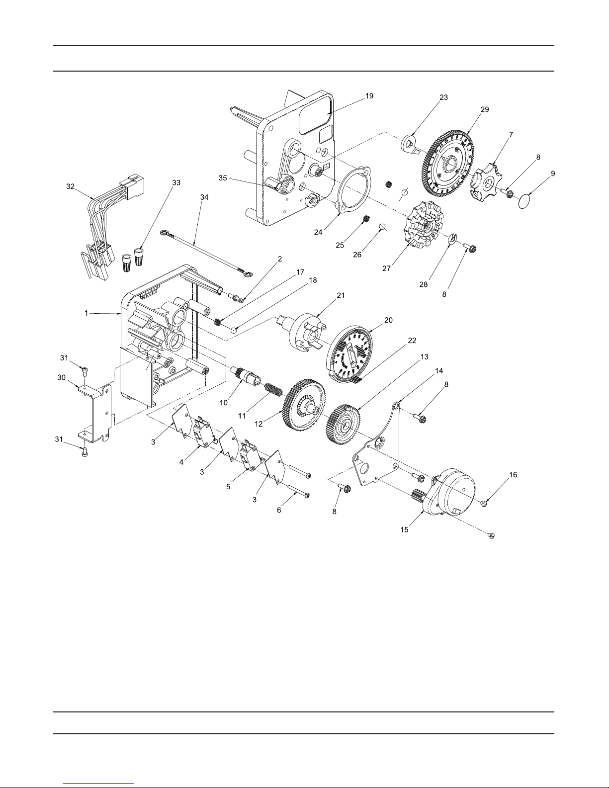
3200 Time Clock Timer Assembly
61502-3200_REVA
For Service Assembly Numbers, See the Back of this Manual

Page 9
3200 Time Clock Timer Assembly
For Service Assembly Numbers, See the Back of this Manual
Item No. Quantity Part No. Description
1..................1 ................... 13870 ......................Housing, Timer, 3200
2..................1 ................... 14265 ......................Clip, Spring
3..................3 ................... 14087 ......................Insulator
4..................1 ................... 10896 ......................Switch, Micro
5..................1 ................... 15320 ......................Switch, Micro, Timer
6..................2 ................... 11413 ......................Screw, Pan Hd Mach, 4-40 x 1 1/8
7..................1 ................... 13886 ......................Knob, 3200
8..................5 ................... 13296 ......................Screw, Hex Wsh, 6-20 x 1/2
9..................1 ................... 11999 ......................Label, Button
10................1 ................... 13018 ......................Pinion, Idler
11 ................1 ................... 13312 ......................Spring, Idler Shaft
12................1 ................... 13017 ......................Gear, Idler
13................1 ................... 13164 ......................Gear, Drive
14................1 ................... 13887 ......................Plate, Motor Mounting
15................1 ................... 18743-1 ...................Motor, 120V, 60Hz, 1/30 rpm, 5600
.......................................... 19659-1 ...................Motor, 24V, 60Hz, 1/30 rpm
16................2 ................... 13278 ......................Screw, Sltd Fillister Hd 6-32 x .156
17................1 ................... 15424 ......................Spring, Detent, Timer
18................1 ................... 15066 ......................Ball, 1/4”, Delrin
19................1 ................... 15465 ......................Label, Caution
20................1 ................... 19210 ......................Program Wheel Assembly
21................1 ................... 13911 ......................Gear, Main Drive, Timer
22................17 ................. 41754 ......................Pin, Spring, 1/16 x 5/8 Stainless Steel, Timer
23................1 ................... 13011 ......................Arm, Cycle Actuator
24................1 ................... 13864 ......................Ring, Skipper Wheel
25................2 ................... 13311 ......................Spring, Detent, Timer
26................2 ................... 13300 ......................Ball, 1/4”, Stainless Steel
27................1 ................... 14381 ......................Skipper Wheel Assembly, 12 Day
.......................................... 14860 ......................Skipper Wheel Assembly, 7 Day
28................1 ................... 13014 ......................Pointer, Regeneration
29................1 ................... 40096-24 .................Dial, 12 AM Regen Assembly, Black
.......................................... 40096-02 .................Dial, 2 AM Regen Assembly, Black
30................1 ................... 13881 ......................Bracket, Hinger Timer
31................2 ................... 11384 ......................Screw, Phil, 6-32 x 1/4 Zinc
32................1 ................... 13902 ......................Harness, 3200
33................2 ................... 40422 ......................Nut, Wire, Tan
34................1 ................... 15354-01 .................Wire, Ground, 4”
35................1 ................... 14007 ......................Label, Time of Day
Page 10
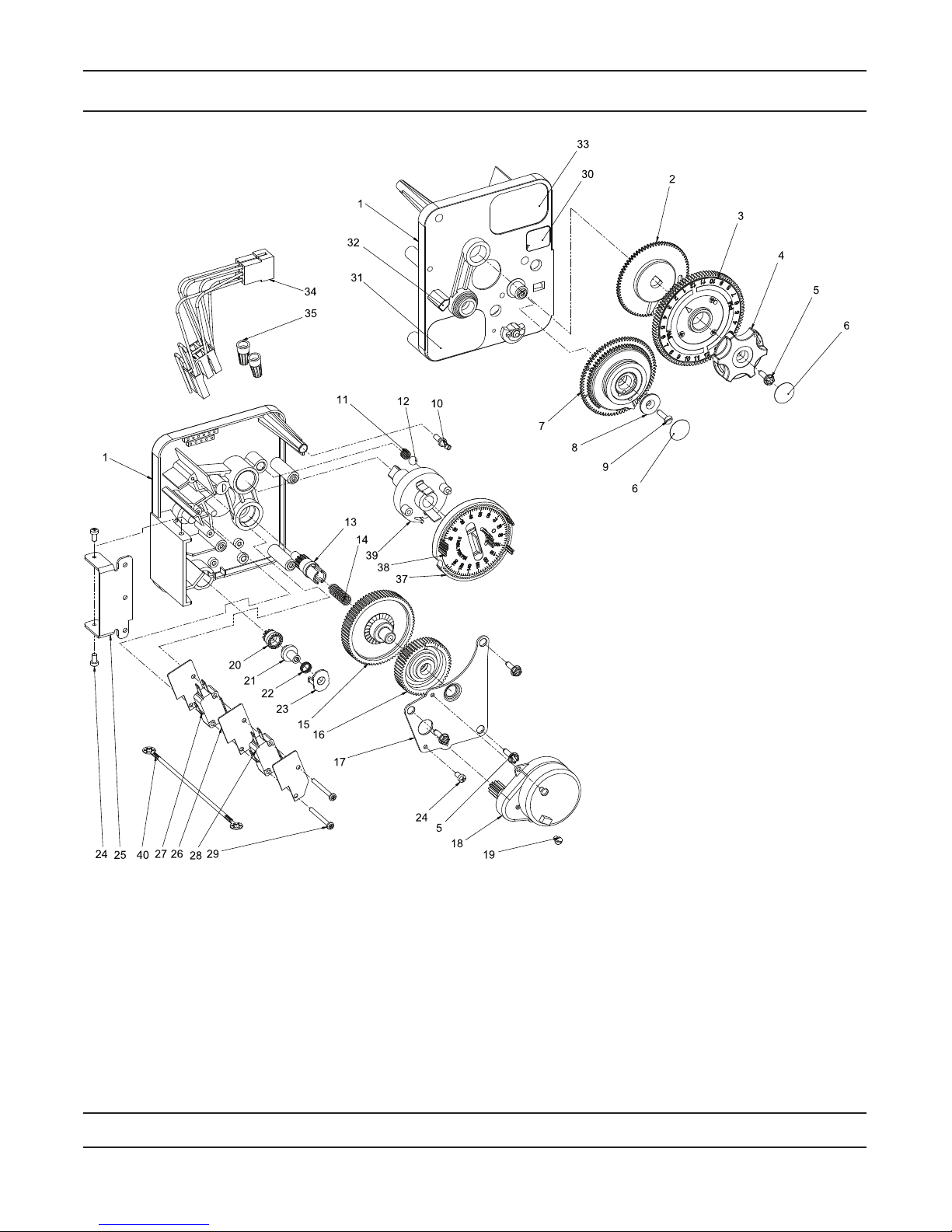
3210 Meter Delayed Timer Assembly
61502-3210_REVA
For Service Assembly Numbers, See the Back of this Manual

Page 11
3210 Meter Delayed Timer Assembly
Item No. Quantity Part No. Description
1..................1 ................... 13870 ......................Housing, Timer, 3200
2..................1 ................... 13802 ......................Gear, Cycle Actuator
3..................1 ................... 40096-02 .................Dial 2AM Regen Assembly, Black
4..................1 ................... 13886 ......................Knob, 3200
5..................4 ................... 13296 ......................Screw, Hex Wsh, 6-20 x 1/2
6..................2 ................... 11999 ......................Label, Button
7..................1 ................... 60405-50 .................Program Wheel, w/2” Std Label, w/People Label Set @ 21
8..................1 ................... 13806 ......................Retainer, Program Wheel
9..................1 ................... 13748 ......................Screw, Flat Head St, 6-20 x 1/2
10................1 ................... 14265 ......................Clip, Spring
11 ................1 ................... 15424 ......................Spring, Detent, Timer
12................1 ................... 15066 ......................Ball, 1/4” Delrin
13................1 ................... 13018 ......................Pinion, Idler
14................1 ................... 13312 ......................Spring, Idler Shaft
15................1 ................... 13017 ......................Gear, Idler
16................1 ................... 13164 ......................Gear, Drive
17................1 ................... 13887 ......................Plate, Motor Mounting
18................1 ................... 18743-1 ...................Motor, 120V, 60Hz 1/30 rpm, 5600
19................1 ................... 13278 ......................Screw, Fillister Hd, 6-32 x .156
20................1 ................... 13830 ......................Pinion, Program Wheel Drive
21................1 ................... 13831 ......................Clutch, Drive Pinion
22................1 ................... 14276 ......................Spring, Meter, Clutch
23................1 ................... 14253 ......................Retainer, Clutch Spring
24................3 ................... 11384 ......................Screw, Phil, 6-32 x 1/4
25................1 ................... 13881 ......................Bracket, Hinge Timer
26................3 ................... 14087 ......................Insulator
27................1 ................... 10896 ......................Switch, Micro
28................1 ................... 15320 ......................Switch, Micro, Timer
29................2 ................... 11413 ......................Screw, Pan Hd Mach, 4-40 x 1 1/8
30................1 ................... 14198 ......................Label, Indicator
31................1 ................... 15465 ......................Label, Caution
32................1 ................... 14007 ......................Label, Time of Day
33................1 ................... 14045 ......................Label, Instruction
34................1 ................... 13902 ......................Harness, 3200
35................2 ................... 40422 ......................Nut, Wire, Tan
36................1 ................... 15354-01 .................Wire, Ground, 4”
37................1 ................... 19210 ......................Program Wheel Assembly
38................17 ................. 41754 ......................Pin, Spring, 1/16 x 5/8 Stainless Steel, Timer
39................1 ................... 13911 ......................Gear, Main Drive, Timer
40................1 ................... 15354-01 .................Wire, Ground 4”
For Service Assembly Numbers, See the Back of this Manual

Page 12
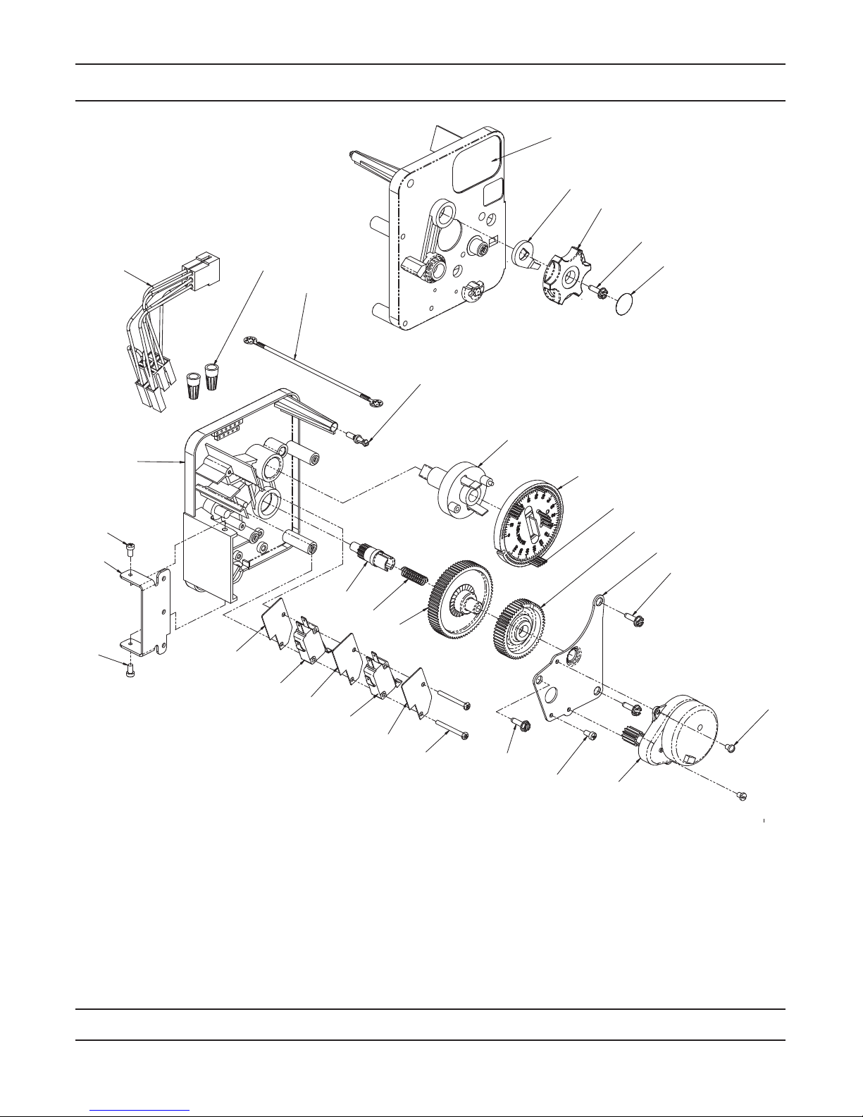
3220 Meter Immediate Timer Assembly
1
2
3
4
5
6
7
8
9
10
11
12
13
14
15
16
17
18 19
20
21
22
23
24
25
26
27
28
29
30
31
32
33
34
35
36 5
1
23
23
21
4

Page 13
3220 Meter Immediate Timer Assembly
Item No. Quantity Part No. Description
1....................1 ......................13870.......................... Housing, Timer
2....................1 ......................15431.......................... Gear, Cycle Actuator, System #5
3....................1 ......................13886.......................... Knob, 3200
4....................4 ......................13296.......................... Screw, Hex Wsh, 6-20 x 1/2
5....................2 ......................11999 .......................... Label, Button
6....................1 ......................60408-50 .................... Program Wheel, W/2” Std Label
7....................1 ......................13806.......................... Retainer, Program Wheel
8....................1 ......................13748.......................... Screw, Flt Hd St, 6-20 x 1/2
9....................1 ......................14265.......................... Spring Clip
10..................1 ......................13018.......................... Pinion, Idler
11 .................. 1 ......................18563.......................... Idler Shaft Spring
12..................1 ......................13017.......................... Gear, Idler
13..................1 ......................13164.......................... Drive Gear
14..................1 ......................13887.......................... Plate, Motor Mounting
15..................1 ......................18743-1 ...................... Motor, 120V, 60 Hz, 1/30 rpm, 5600
16..................2 ......................13278.......................... Screw, Sltd Fillister Hd
17..................1 ......................14502.......................... Pinion, Program Wheel
18..................1 ......................14501.......................... Clutch, Drive Pinion
19..................1 ......................14276.......................... Meter Clutch Spring
20..................1 ......................14253.......................... Retainer, Clutch Spring
21..................3 ......................11384 .......................... Screw, Phil, 6-32 x 1/4 Zinc
22..................1 ......................13881.......................... Bracket, Hinge Timer
23..................3 ......................14087.......................... Insulator
24..................1 ......................15414-00 .................... Micro Switch
25..................1 ......................15320.......................... Switch, Micro, Timer
26..................2 ......................11413 .......................... Screw, Pan Hd Mach, 4-40 x 1-1/8
27..................1 ......................14198.......................... Label, Indicator
28..................1 ......................15465.......................... Label, Caution
29..................1 ......................14007.......................... Label, Time of Day
30..................1 ......................15148.......................... Label, Instruction
31..................1 ......................40617.......................... Harness, 3220
32..................2 ......................40422.......................... Nut, Wire, Tan
33..................1 ......................15354-01 .................... Wire, Ground, 4”
34..................1 ......................19210-05 .................... Program Wheel Assembly, 9000/3230
35..................17 ....................41754.......................... Pin, Spring, 1/16 x 5/8 Stainless Steel, Timer
36..................1 ......................15055.......................... Gear, Main Drive
Page 14
3230 Remote Start Timer Assembly
1
2
3
4
5
6
7
8
9
10
11
12
13
14
15
16
17
18
20
8
8
3
3
24
24
24
23
21
25 26
27
22

Page 15
3230 Remote Start Timer Assembly
Item No. Quantity Part No. Description
1....................1 ......................13870.......................... Housing, Timer
2....................1 ......................14265.......................... Spring Clip
3....................3 ......................14087.......................... Insulator
4....................1 ......................15314.......................... Micro Switch
5....................1 ......................15320.......................... Switch, Micro, Timer
6....................2 ......................11413 .......................... Screw, Pan Hd Mach, 4-40 x 1-1/8
7....................1 ......................13886.......................... Knob, 3200
8....................4 ......................13296.......................... Screw, Hex Wsh, 6-20 x 1/2
9....................1 ......................11999 .......................... Label, Button
10..................1 ......................13018.......................... Pinion, Idler
11 .................. 1 ......................18563.......................... Idler Shaft Spring
12..................1 ......................13017.......................... Gear, Idler
13..................1 ......................15055.......................... Drive Gear
14..................1 ......................13887.......................... Plate, Motor Mounting
15..................1 ......................18743-1 ...................... Motor, 120V, 60 Hz, 1/10 rpm
......................1 ......................19659-1 ...................... Motor, 24V, 60 Hz 1/30 rpm
16..................2 ......................13278.......................... Screw, Sltd Fillister Hd
17..................1 ......................15313.......................... Label, Caution
18..................1 ......................19210-05 .................... Program Wheel Assembly, 3200
20..................1 ......................15055.......................... Main Drive Gear
21..................17 ....................41754.......................... Pin, Spring, 1/16 x 5/8 Stainless Steel, Timer
22..................1 ......................13011 .......................... Cycle Actuator Arm
23..................1 ......................13881.......................... Bracket, Hinge Timer
24..................3 ......................11384 .......................... Screw, Phil, 6-32 x 1/4 Zinc
25..................1 ......................16336.......................... Harness, 3230R
26..................2 ......................40422.......................... Nut, Wire, Tan
27..................1 ......................15354-01 .................... Wire, Ground, 4”

Page 16
29
1
4
5
7
8
2
9
3
10
11
28
27
19
17
26
12
21
16
13
15
14
20
25
18
24
22
23
30
6
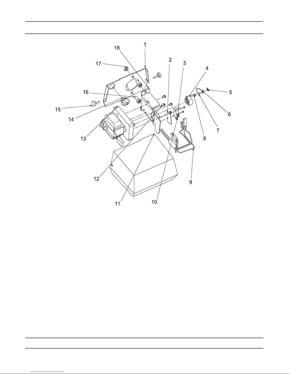
Upper Designer Powerhead Assembly
For Service Assembly Numbers, See the Back of this Manual

Page 17
Upper Designer Powerhead Assembly
Item No. Quantity Part No. Description
1 .................... 1 ..................... 19291-020 ................................Cover, Designer
2 .................... 1 ..................... 14822 .......................................Harness, 2900
...................... 1 ..................... 16563 .......................................Harness, 2900/3900/Sys 7
...................... 1 ..................... 18585 .......................................Harness, 3900, Aux Switch
...................... 1 ..................... 40395 .......................................Harness, Drive, Sys#7, Multi
...................... 1 ..................... 40400 .......................................Harness, Drive, Designer/Environmental
3 .................... 1 ..................... 40175-01 ..................................Wire, Ground, Commercial Valves
4 .................... 1 ..................... 3200 Meter Timer Assy ............3200 Meter Timer Assembly
...................... -......................3200 Clock Timer Assy.............3200 Clock Timer Assembly
5 .................... 2 ..................... 14923 .......................................Screw, Pan Hd Mach, 4-40 X 1
6 .................... 5 ..................... 10872 .......................................Screw, Hex Wsh, 8-32 X 17/64
7 .................... 2 ..................... 10218 .......................................Switch, Micro
8 .................... 3 ..................... 10302 .......................................Insulator, Limit Switch
9 .................... 1 ..................... 60160-15 ..................................Drive Cam Assy, STF, Blue, 2900
...................... 1 ..................... 60160-30*.................................Drive Cam Assy, Upflow
...................... 1 ..................... 60160-31*.................................Drive Cam Assy, Upflow, Variable
10 .................. 1 ..................... 41543 .......................................Motor, Drive, 115V, 50/60 Hz
...................... 1 ..................... 40384 .......................................Motor, Drive, 115V, 60Hz, SP, Fam 1
...................... 1 ..................... 42579 .......................................Motor, Drive, 24VAC/DC, 50/60 Hz
...................... 1 ..................... 40386 .......................................Motor, Drive, 220V, 50/60 Hz, SP Fam 1
11................... 1 ..................... 10269 .......................................Nut, Jam, 3/4-16
12 .................. 1 ..................... 10896 .......................................Switch, Micro
13 .................. 1 ..................... 10338 .......................................Pin, Roll, 3/32 x 7/8
14 .................. 1 ..................... 12472 .......................................Cam Assy, Tri-Stack, After RR
...................... 1 ..................... 12777 .......................................Cam, Shut-Off Valve
...................... 1 ..................... 15770 .......................................Cam Assy, Special Tri-Stack, After Brine Fill
...................... 1 ..................... 15805 .......................................Cam, SVO
...................... 1 ..................... 19749*......................................Cam, Brine, 2750, U/F, Variable
...................... 1 ..................... 19887*......................................Cam, Brine, 2750 U/F Std
15 .................. 2 ..................... 11805 .......................................Screw, Rd Hd, 4-40 X 5/8
16 .................. 1 ..................... 14822 .......................................Harness, 2900
17 .................. 1 ..................... 40174 .......................................Terminal Block, Green/Yellow Commercial
18 .................. 1 ..................... 40264 .......................................Backplate, w/t - Screws, 2750, 2850, 2900
19 .................. 2 ..................... 15250 .......................................Label, Terminal Strip
20 .................. 1 ..................... 10712 .......................................Fitting, Brine Valve
21 .................. 6 ..................... 41084 .......................................Terminal Block, Segment, Gray
22 .................. 2 ..................... 13296 .......................................Screw, Hex Wsh, 6-20 X 1/2
23 .................. 1 ..................... 11545 .......................................Power Cord, 4’ European, Black
...................... 1 ..................... 19303 .......................................Power Cord, 8’, Australian
...................... 1 ..................... 19885 .......................................Power Cord, Japanese, 110V/120V
...................... 1 ..................... 40084-12 ..................................Power Cord, 12’US, ROUND, 120V Sys 5, 6, 7
...................... 1 ..................... 40085-12 ..................................Power Cord, 12’ US, Round, 240V
24 .................. 1 ..................... 13547 .......................................Strain Relief, Flat Cord Heyco #30-1
...................... 1 ..................... 13547-01 ..................................Strain Relief, Euro Round Cord
...................... 1 ..................... 13547-02 ..................................Strain Relief, U.S. Round
...................... 1 ..................... 14924 .......................................Strain Relief, Heyco #1247
25 .................. 1 ..................... 15806 .......................................Plug, Hole, Heyco #2693
26 .................. 1 ..................... 41085 .......................................Endplate, Terminal Block, Gray
27 .................. 1 ..................... 17421 .......................................Plug, 1.20 Hole Heyco #2733
28 .................. 1 ..................... 13741 .......................................Plug, 3/4”, Knock-Out, Heyco #2683
29 .................. 2 ..................... 10300 .......................................Screw, Slot Hex Wsh, 8-18 X 3/8 Type “B” RC44-47
30 .................. 1 ..................... 40038-03 ..................................Label, Voltage, 120V, 3200ET
Not Shown:
...................... 1 ..................... 15216 .......................................Meter Cable Assy, 15.25”
...................... 1 ..................... 15879 .......................................Cable Guide Assy, 2900
*Upflow Only
For Service Assembly Numbers, See the Back of this Manual
Page 18
Lower Designer Powerhead Assembly
For Service Assembly Numbers, See the Back of this Manual
Item No. Quantity Part No. Description
1 .................... 1 ..................... 14770 .......................................Backplate, Lower 2900
2 .................... 1 ..................... 10302 .......................................Insulator, Limit Switch
3 .................... 1 ..................... 10218 .......................................Switch, Micro
4 .................... 1 ..................... 14775 .......................................Cam, Drive, 2900
5 .................... 1 ..................... 10250 .......................................Ring, Retaining
6 .................... 1 ..................... 14759 .......................................Link, Piston Rod
7 .................... 1 ..................... 14784 .......................................Bearing, Connecting Rod
8 .................... 1 ..................... 41022 .......................................Pin, Roll, 2900 Lower
9 .................... 1 ..................... 40402 .......................................Harness, Lead, Sys #4, Designer
10 .................. 2 ..................... 19849 .......................................Screw, Pan Hd, 4-40 X 5/8
11................... 1 ..................... 14800-02 ..................................Cover, Dust, Lower, 2900, Black
12 .................. 4 ..................... 10872 .......................................Screw, Hex Wsh, 8-32 X 17/64
13 .................. 1 ..................... 40387 .......................................Motor, Drive, 115V, 60Hz, SP FAM 2
...................... 1 ..................... 42580 .......................................Motor, Drive, 24VAC/DC, 50/60 Hz
...................... 1 ..................... 40389 .......................................Motor, Drive, 220V, 50/60 Hz, Sp Fam 2
14 .................. 1 ..................... 14924 .......................................Strain Relief Heyco #1247
15 .................. 2 ..................... 19367 .......................................Screw, Designer Cover, Thumb 8-32 Black UV Stable
16 .................. 2 ..................... 11224 .......................................Screw Hex Hd, 5/16 - 18 x 5/8 MS 410 Stainless Steel
17 .................. 2 ..................... 16346 .......................................Nut, Hex, Jam, 5/16-18
18 .................. 1 ..................... 14769 .......................................Bracket, Motor, 2900

Page 19
Notes
Page 20
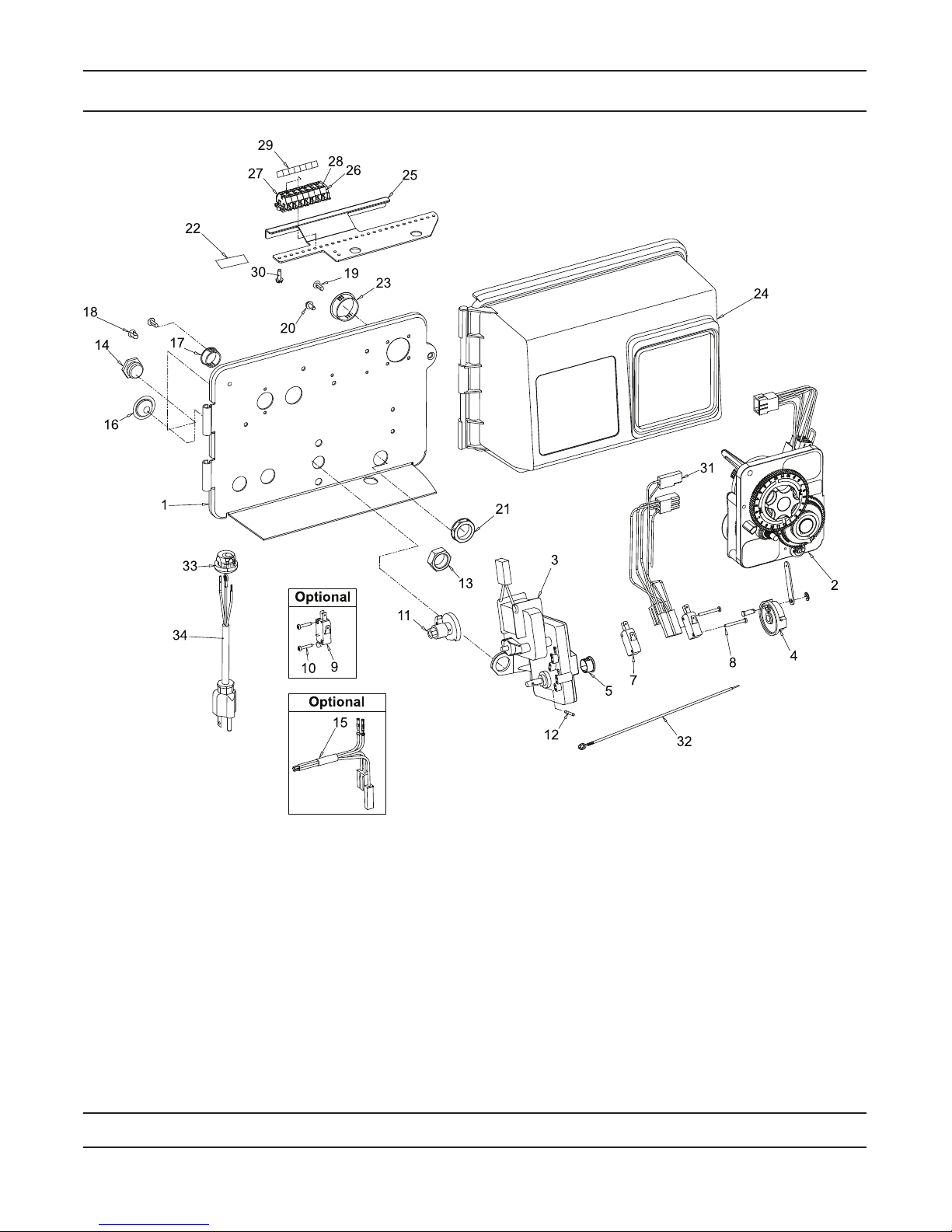
Upper Environmental Powerhead Assembly
61501-2900_REVC
For Service Assembly Numbers, See the Back of this Manual
Table of contents
Other Fleck Plumbing Product manuals

Popular Plumbing Product manuals by other brands

CANTERBURY
CANTERBURY Z2208--27 quick start guide

American Standard
American Standard Williamsburg 0554.700 Specification sheet

Moen
Moen INS916D user manual

American Standard
American Standard PORTSMOUTH 4285.001 installation instructions

miseno
miseno MNOTS250CP instructions

MAAX
MAAX 107223 installation instructions


