Fleet Management MLT-400i User manual

MLT-400i Installation Guide
11/18/2009 FMS MLT-400i Installation Guide 4.3 1

MLT-400i Installation Guide
11/18/2009 FMS MLT-400i Installation Guide 4.3 2
Notice
This installation guide is published and copyrighted by Fleet Management Solutions
(FMS). All information and specifications in this document are subject to change without
notice. Nothing in this document is intended to create additional or separate warranties or
guarantees.
Installation Requirements
Fleet Management Solutions recommends that you contact a professional installation
provider. Please contact FMS for an approved installation provider list or to arrange in-
stallation training. All installations must be done by approved personnel to ensure war-
ranty coverage. Damage caused by incorrect installation will void the warranty.
© 2009 Fleet Management Solutions, All Right Reserved.
2007 & 2008 Inc. 500Honoree
3426 Empresa Drive
Suite 100
San Luis Obispo, CA 93401
Tel: (800) 999-2169
Fax: (805) 787-0509
E-mail: support@fmsgps.com
Web: www.fmsgps.com

MLT-400i Installation Guide
11/18/2009 FMS MLT-400i Installation Guide 4.3 3
Table of Contents
Notice 2
Installation Requirements 2
Introduction 4
Recommended Equipment.........................................................................4
Recommended Supplies.............................................................................4
Installation Documentation........................................................................4
Install Antenna 5
Safety Considerations................................................................................5
Determine the Best Location......................................................................5
Connect Power, Ignition and I/O 6
MLT-400iO OBDII Connection ....................................................................6
MLT-400i Three-Wire Connection ...............................................................6
MLT-400i/400iO I/O Connection.................................................................8
Securing the Unit 8
Validate Installation 9
Observe LED Lights...................................................................................9
Validate Communications with MDT............................................................9
Validate Communications with Fleet Central................................................9
Troubleshooting 10
Case...................................................................................................... 10
Help ...................................................................................................... 10
Appendix A – ANTIR01 Antenna Installation 11
Appendix B – Installation Checklist 13

MLT-400i Installation Guide Introduction
Introduction
1
This installation manual covers the installation of the MLT-400i and MLT-400iO.
The MLT-400i/O includes a GPS receiver and a two-way satellite communications modem.
Options include a built-in, on-board diagnostic interface (OBDII), an in cab Message Display
Terminal (MDT) and ignition disable relay.
Recommended Equipment
•Digital Volt/Ohm Meter (DVOM)
•Soldering iron/solder
•Wire strippers/cutters
•Cordless Drill
•Drill bits (step bit or Unibit, #36,
19/32”, etc.)
•Flash light
•Standard and Metric socket set
•Screwdrivers (standard, Phillips,
Hex, Torx)
Recommended Supplies
sealant
screws
e
) for tamper
Installation Checklist to capture required installation and system
alidation information.
ation. Phase 2 is system
validation.
the
modem IMEI Serial Number(ESN):
•Electrical tape
•Velcro
•Silicon
•Tie-Wraps
•Sheet metal
•18 gauge wire
•2 amp ATC fus
•Torque Seal (blue
deterrent
Installation Documentation
Appendix B includes an
v
•The checklist is designed to be com-
pleted in two phases. Phase 1 is instal-
lation inform
•You will need to locate the Electronic
Serial Number on the label located on
the back of the unit. This identifies
Vehicle Name(Asset Name) to the
11/18/2009 FMS MLT-400i Installation Guide 4.3 4

MLT-400i Installation Guide Install Antenna
Install Antenna
The MLT-400i antennas combine GPS and Iridium satellite antennas. The ANTIR01 is a
permanent mount (see Appendix A for additional information); ANTIR02 is a suction cup
window mount antenna. Proper installation is critical to achieve optimum performance.
Safety Considerations
•Some locations do not allow suction
mount antennas on the windshield.
Check your local regulations
Determine the Best Location
•Locate the antenna for an unob-
structed view of the sky, avoid
windscreens, ladder racks and other
radio antennas (minimum radius of 2
feet is recommended)
•Orient the antenna horizontally
•Ensure that the antenna GPS cable
connects to the MLT-400i GPS cable
and the Iridium cable connects to the
MLT-400i Iridium cable (they are
color coded blue and black respec-
tively)
•Apply inspection torque seal if
desired (see below)
•Check antenna cable length will
reach to desired location; antennas
typically include 12 feet of cable
•Coil and secure any loose or extra
lengths of antenna cable, do not
allow cables to kink
•The antenna must be attached to the
MLT-400i prior to attaching power
Tamper Deterrent – Torque Seal
For customers wanting to create a visual tamper deterrent for the OBDII connector, Torque
Seal may be used to create a visual seal. FMS does not endorse or warranty Torque Seal.
•Apply Torque Seal “across”
desired connectors such as the
OBDII and antenna
•Torque Seal may be pur-
chased through Organic
Product Company
(http://www.opcompany.com)
•Do Not apply Torque Seal in-
side any connector so as to
interfere with electrical
continuity
2
11/18/2009 FMS MLT-400i Installation Guide 4.3 5

MLT-400i Installation Guide Connect Power, Ignition and I/O
Connect Power, Ignition and I/O
3
Two versions of the MLT-400i are available (check the product label located on the back of
the unit to determine which one you have): 1) the MLT-400iO is OBDII compatible; 2) the
standard MLT-400i uses a three-wire connection. Both are described below.
MLT-400iO OBDII Connection
•Ensure your vehicle is OBDII com-
patible, read the FMS OBDII “How
to Determine Compatibility”
available for download on Fleet
Central from
Admin|Support|UserGuides
•Connect the right angle OBDII
connector in to the vehicle OBDII
connector
•The OBDII connector may be
located behind a panel, check your
vehicle documentation for the
location
•After installation validation, tie wrap
the connectors together, if possible,
and add a dot of inspection/torque
seal to detect tampering
•If your vehicle is not OBDII com-
patible, you can still use the modem
with the Three-Wire Connection
below. See inset below on Using the
MLT-400iO in Three-Wire Mode.
MLT-400i Three-Wire Connection
The MLT-400i is shipped with one in-line 2-amp fuse attached to the power cable. This fuse
should be installed as close as possible to the primary 12 or 24 volt source connection. If the
power connection is more that 1-2 feet from the fuse an additional fuse must be added as
close to the power connection as possible should a short occur in the wiring. If a fuse is
added or replaced, it should be of the same type as originally supplied from the factory. The
original fuses supplied is one (2 Amp ATC BUSS fuse).
Use care when routing the power cable. Route the cables where they will be protected and
use commonly accepted install practices for aftermarket automotive electronic devices.
Using The MLT-400iO in Three-Wire Mode
•Disconnect the OBD-II connector and attach ignition and power wires, (see MLT-400i
Three-Wire Connection above for more details)
•Contact FMS Technical Support to issue the Reset Configuration Command
•If you are using a Message Display Terminal (MDT-PRO), you must also connect both
the modem AND the MDT (using the white two pin connector) to the same power source
in addition to performing the steps above.
•Solder your connections (see Poke and Wrap below)
11/18/2009 FMS MLT-400i Installation Guide 4.3 6

MLT-400i Installation Guide Connect Power, Ignition and I/O
11/18/2009 FMS MLT-400i Installation Guide 4.3 7
•Ensure that connections are mechanically sound and properly insulated
•Use high quality electrical tape or shrink tubing, cheap tape will unravel in hot weather,
making it a poor insulator
•Never use “t-tap” connectors (poor quality mechanical type connection). Never “twist
and tape” without soldering your connection
Black Wire – Ground
•Connect to a ground wire in a harness or
•Connect to a bolt in the vehicle chassis
Red Wire – Continuous Power
•Attach the Red wire to the battery power or
•Connect, with the key Off, to a constant power of 9 to 24 volts DC. Use a voltmeter
and ensure that the voltage does not drop below 9 volts when starting the vehicle.
Green Wire – True Ignition
•Attach the green wire to true ignition source of 9 to 30 volts DC.
•Do not connect to accessory power
•To determine true ignition:
1. Select a wire.
2. With the key OFF, use a voltmeter to measure the DC voltage is between 0-2 VDC.
3. Turn the key ON and confirm the voltage is equal or greater than 11-13 VDC. The
voltage must not drop below 9 VDC when starting the vehicle.
4. Turn the key OFF, confirm the voltage is now 0-2 VDC.
Poke and Wrap
1. Expose approximately 1/2” of bare wire.
2. Use a fine point tool to separate the wire strands.
3. Insert the end of the bare wire from your electronic device.
4. Push the wire to one end of the loop in preparation for
wrapping.
5. Wrap your wire with the existing automotive wire.
6. Solder your connection.
7. Using a piece of electrical tape, wrap the connection and
½” of insulation on either side of the exposed wires.
8. Place a zip tie around the section where the bare wires are
located under the electrical tape.

MLT-400i Installation Guide Securing the Unit
11/18/2009 FMS MLT-400i Installation Guide 4.3 8
MLT-400i/400iO I/O Connection
Note, when installing the modem, leaving easy access to the serial cable will facilitate any
code updates.
If additional I/O connections are desired for analog/digital inputs or digital outputs, the wire
harness is defined below.
MLT-400i Wire Harness Description
Wire Color Use Operating Range
Red *Constant power source. Not accessory power. 9-30VDC
Black * Chassis Ground Ground
Green *True Ignition Source 9-30VDC
Purple *Signal Ground. Connect at analog sensor’s ground. Ground
Orange *Analog/Digital IN # 0 0-5VDC
Brown *Analog/Digital IN # 1 0-5VDC
Grey *Analog/Digital IN # 2 0-5VDC
Blue *Digital IN # 0 3-30VDC
Yellow *Digital OUT # 1 12VDC, 50mA
White *Digital OUT # 2 12VDC, 50mA
Notes: Cap Off any sensors not being used.
Securing the Unit
4
1. Before securing the unit, typically under the dashboard, record the IMEI/Serial Number
(ESN), Vehicle Name (Asset Name), Odometer and if available Engine Hours on the
Installation Checklist in Appendix B.
2. Use tie-wraps to mount the unit securely to a stable bracket.
3. If possible, orient the unit so the LED indicators are visible.
4. Do not place the unit near moving parts, or next to any of the vehicle’s pedals
5. Loosely bundle any excess antenna cable, power wiring and unused I/O signals
6. Leaving easy access to the 9-pin serial cable will allow for code updating.

MLT-400i Installation Guide Validate Installation
11/18/2009 FMS MLT-400i Installation Guide 4.3 9
Validate Installation
5
Take the vehicle outside where the antenna has a clear view of the sky in all directions. Avoid
locations with metal overhangs, tall buildings and trees. Conduct installation verification after
the vehicle has been running outside for at least 15 minutes.
Observe LED Lights
•Power LED - Relates to GPS
oGreen Solid - GPS fix acquired
oYellow Blinking - GPS Searching
oRed Blinking one per second - GPS hardware failure
•Signal LED - Relates to Iridium
oGreen Solid - Signal detected, modem is ready
oYellow Blinking - modem is initializing
oRed Blinking - modem hardware failure
oOff - No Iridium satellite detected / cable problem.
Validate Communications with MDT
If you have a Message Display Terminal (MDT) installed, you can begin the validation process
by going to the System Status|Diagnostics Menu. The tests encompass the local connection
between the MDT and MLT-400i, the Iridium signal strength, the GPS satellite count, as well
as ignition wiring (and type), and the optional Ignition Enable/Disable feature.
Validate Communications with Fleet Central
•If you don’t have access to the FMS Fleet Central web application please call FMS
Technical Support at (800) 999-2169, Monday through Friday, 6:00 am to 6:00 pm
Pacific Time. Our friendly and knowledgeable support staff will take the ESN Number
of your unit and will verify data transmission.
•If you have access to the FMS Fleet Central web application (password and user id re-
quired) log on at www.fmsgps.com. Run a “History Report” for the current date to see
if the data from your unit has been transmitted. The first messages you should see from
your unit are these:
oHost Synchronization: the message sent when it reboots and receives a GPS lock
oIgnition ON: the message sent when the vehicle is started
oIgnition OFF: the message sent when the vehicle is turned off
If you gave the unit 30 minutes to transmit the data and still don’t see the mes-
sages, it is possible the installation was not done properly (see Troubleshooting
Section below).
oVerify the report information correctly locates your vehicle
oVerify/set the time zone for the vehicle
oRecord validation information on the Installation Checklist in Appendix B

MLT-400i Installation Guide Validate Installation
11/18/2009 FMS MLT-400i Installation Guide 4.3 10
Troubleshooting
A summary of various troubleshooting cases is presented below. The FMS Knowledge Base is
a searchable resource of information related to common questions. Login to Fleet Central to
access the Knowledge Base on the Admin|Support|Knowledge Base Screen.
Note: If the GPS and Iridium cables were swapped and then reconnected, you will need to wait
at least 30 minutes for a first time GPS fix.
Case
# Case Possible Cause Action
1 There are no Ignition
On/Off messages
Green wire is not
connected correctly
Verify that the Green Wire receives
≥9VDC when starting vehicle.
2 There is no Host
Synchronization
message
No GPS fix – GPS
antenna does not
function properly
Verify antenna installation.
Verify no objects obstructing antenna’s
view of sky.
3 There are no mes-
sages at all
Antenna does not
function properly or
unit is not activated
Swap unit with a known good vehicle
installation. Verify antenna installation.
Verify that the unit is activated.
4 No LED activity on
MLT-400iO - OBDII
Blown fuse
powering OBDII
connector
The OBDII fuse typically powers the
cigarette lighter also, check the fuse
w/VOM and replace as necessary
5 Power LED:
Yellow/blinking
No GPS fix Wait at least 30 minutes for first time
fix. Verify antenna installation. Verify
no obstructing antenna’s view of sky.
6 Power LED:
Red Blinking
GPS hardware
failure
Call Technical Support.
7 Signal LED:
Off
No Iridium satellite
detected
Verify antenna installation. Verify no
obstructing antenna’s view of sky.
8 Signal LED:
Red Blinking
Iridium hardware
failure
Call Technical Support.
Help
Access Source Location
Online: Knowledge Base Admin|Support|Knowledge Base
FAQs Admin|Support|FAQs
Fleet Central User’s Guide Admin|Support|Fleet Central User’s Guide
Open a Support Ticket Admin|Support|Open Support Ticket
E-mail: - Contact FMS Technical Support at:(800) 999-2169
Phone: - Contact FMS Technical Support at:
Mail: - Fleet Management Solutions
3426 Empresa Drive, Suite 100
San Luis Obispo, CA, USA 93401
6

MLT-400i Installation Guide Appendix A – ANTIR01 Antenna Installation
11/18/2009 FMS MLT-400i Installation Guide 4.3 11
Appendix A – ANTIR01 Antenna Installation
•Keep antenna at least two feet from all other antennas
•Size: 3.5”L, 2.2”W, 0.8”H
•The ANTIR01 does not require a metal mounting surface
•Recommended holes: 0.5937” (19/32), 2 places, clear-
ance for Iridium and GPS connectors; 0.107 (#36), 4 places,
size for 6-32 self tapping screws
•Hole plug: for 0.5937 holes use Heyco 1675 (black) or 1676
(white); for use when removing antenna
•Use hole template below as a drill guide. Check printed tem-
plate is sized to 1.660” between holes as dimensioned on the
template.
•The connector located closest to the center is for the GPS ca-
ble (Blue), the connector located closest the end is for the
Iridium cable (Black)
•Verify the template size with the actual antenna in case any scaling issues have
occurred during the printing process.
1.660"
Iridium (Black)
.5937" (19/32)
Diameter
GPS (Blue)
.5937" (19/32)
Diameter
.107" (#36)
Diameter
4 Places
1.660"
Iridium (Black)
.5937" (19/32)
Diameter
GPS (Blue)
.5937" (19/32)
Diameter
.107" (#36)
Diameter
4 Places

MLT-400i Installation Guide Appendix A – ANTIR01 Antenna Installation
11/18/2009 FMS MLT-400i Installation Guide 4.3 12
MLT-400i Installation Guide Appendix B - Installation Checklist
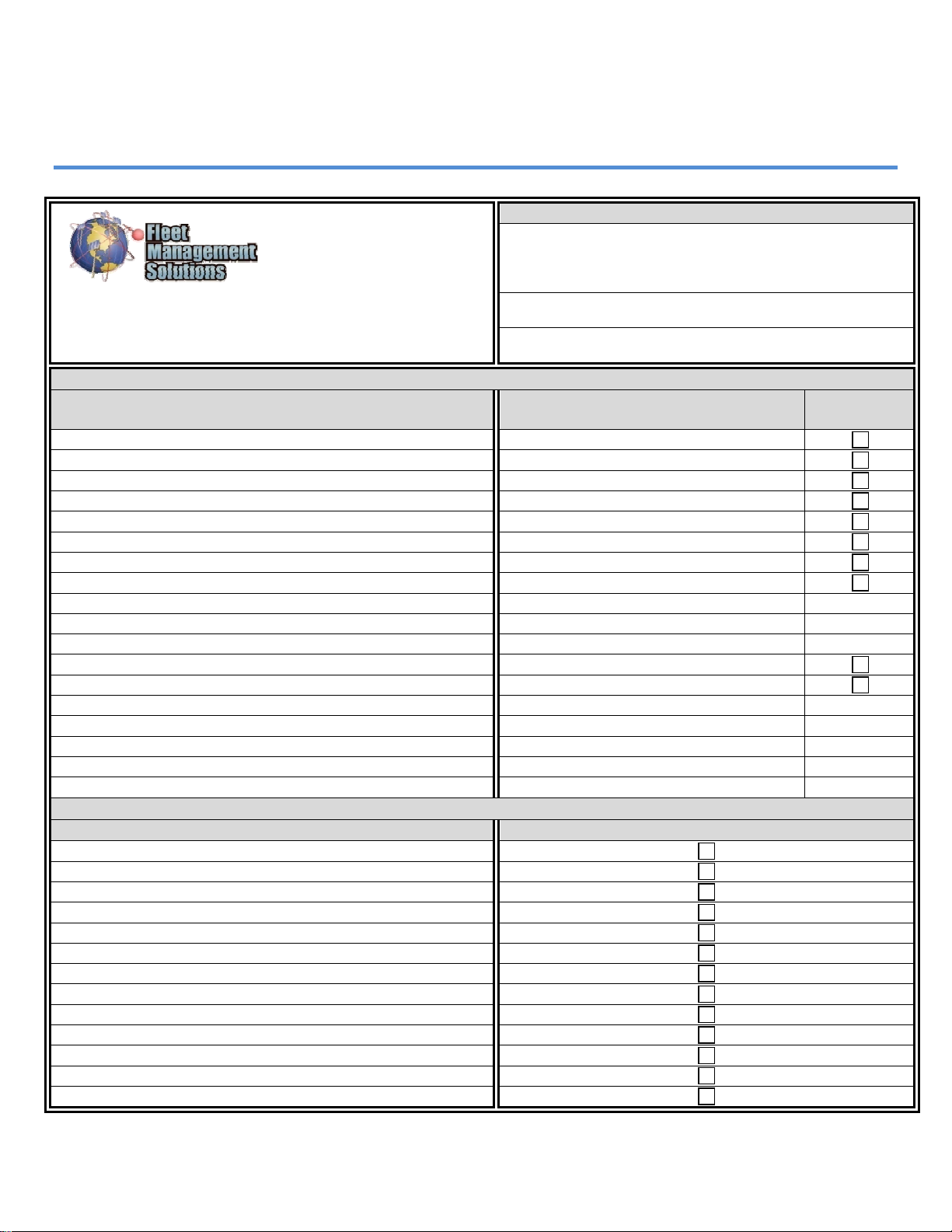
Appendix B – Installation Checklist
Single Unit Instal-
lation Checklist
*Customer
Use this form to track which MLT-400i units are installed in
which vehicles. *Indicates required information. Contact
FMS Technical Support at: (800) 999-2169
Phase 1 - Installation Information (To be completed by the installer)
Information to be Collected Recorded Information Entered into
Fleet Central
*IEMI/Serial Number (ESN):
*Vehicle Name (Asset Name):
*VIN Number:
Model Year:
License Plate Number:
MFG:
Model:
Vehicle Color:
State:
Driver Name:
Driver Position (Elec, Mech, Safety, etc.):
*Odometer:
*Diesel or Gas:
Office Reports to:
Misc (Superintendant’s Name, Assigned to, __________, etc):
*Date Installed:
*Location Installed at:
*Installed by:
Phase 2 – Validation Information (To be completed by Fleet Central Administrator w/Installer)
Operational Check List Verified in Fleet Central
Move to Installed:
Host Sync:
Ignition On:
Ignition Off:
Verify Location Accuracy:
Set Odometer:
Verify/Set Time Zone:
Assigned to appropriate Group(s):
MDT Only - Email Send:
MDT Only - Email Receive:
MDT Only - Quick Message Send:
MDT Only - Quick Message Received:
IGNDRA Only - Ignition Disable Relay:
11/18/2009 FMS MLT-400i Installation Guide 4.3 13
MLT-400i Installation Guide Appendix B - Installation Checklist
11/18/2009 FMS MLT-400i Installation Guide 4.3 14
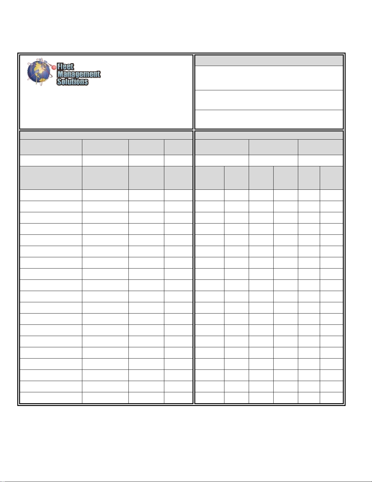
Multiple Unit
Installation Checklist
Customer
Use this form to track which MLT-400i units are installed in
which vehicles and to capture Odometer and Engine Hours (if
available). This information will be entered into Fleet Central
during the validation phase. Contact FMS Technical Support
at: (800) 999-2169
Phase 1 - Installation Information Phase 2 – Validation Information
Date Installer Name Installer
Phone #
Install
Location
Date Validator Name Validator
Phone #
IEMI/Serial Number
(ESN)
Vehicle Name
(Asset Name)
Odometer Engine
Hours
• Move
to
Installed
9
Host
Synch
9Ig-
nition
On
9Ig-
nition
Off
9
Loc-
ation
9
Time
Zone
Table of contents


