Fleetminder MDVR-IP4/IP8 HD User manual

Operating Instruction for
FM MDVR-IP4/IP8 HD MDVR
Dear users, functional setting of this device requires
some expertise. Therefore, please carefully read and
fully understand the instruction before use.
Thank you for choosing our product. Difference between models or product upgrading may
result in appearance or features different from those described in the instruction; thus, it
all depends on the actual product or you can contact the manufacturer. Information
contained herein is subject to irregular change without prior notice.

This instruction is applicable for FM MDVR-IP4/IP8 HD series MDVR products. Information contained herein
may not be technically accurate. If any conflict between the product and the instruction is found during usage, it
all depends on the actual product or you can contact the manufacturer. Information contained herein is subject to
irregular change without prior notice.
1. Installation Environment
To extend the service life, please try to install the device in a place where vibration is weak;
To ensure normal heat dissipation, do not install the device in a poorly-ventilated area (such as trunk), and
also keep about 15 cm away from other objects on the same level;
The device shall be horizontally installed and protected against water, humidity and lightning; in addition,
keep the vehicle still during installation to prevent damage to the device due to falling off;
To ensure safe operation, keep the device, camera, cables and other accessories out of reach of passengers
and driver.
2. Avoid Electric Shock and Fire
8V-36V DC power supply is used for this device. Please note the positive and negative terminals during
connection to prevent short circuit;
Please power the device off before connecting any peripheral ;
Do not touch the power supply and the device with wet hands;
Do not spray liquid on the device to prevent internal short circuit or fire;
Do not place any other device directly on top of the camera;
Statement
Usage Precautions

Do not disassemble the housing without authorization to avoid damage or electric shock;
3. Transport and Handling
To prevent incidental damage to the device during transport. Handle the device with due care. The original
packaging materials and carton are preferred;
Power the device off before handling or part replacement to prevent any damage;
Table of Contents
一、Product Description.................................................................................................................................... - 1 -
1. Product Overview .................................................................................................................................. - 1 -
2. Technical Specifications......................................................................................................................... - 1 -
3.主机介绍................................................................................................................................................. - 6 -
3. Introduction to Mainframe..................................................................................................................... - 6 -
II. Device and Installation ................................................................................................................................ - 10 -
1. Installation............................................................................................................................................ - 10 -
Step 1: Open the protective cover .................................................................................................... - 10 -
Step 2: Prepare the HDD.................................................................................................................. - 10 -
Step 3: Insert the HDD..................................................................................................................... - 11 -
Step 4: Install SIM and SD cards ..................................................................................................... - 12 -
Step 5: Lock the electric lock........................................................................................................... - 12 -
Step 6: Install the mainframe ........................................................................................................... - 13 -
Step 7: Install GPS, 3G/4G, WiFi antenna....................................................................................... - 13 -
Step8:接电源线............................................................................................................................. - 14 -
Step 8: Connect the power cord ....................................................................................................... - 14 -
Step 9: Connect the display output unit ........................................................................................... - 15 -
Step 10: Alarm input and output cable............................................................................................. - 15 -
Step 11: RS232/RS485 device connection....................................................................................... - 16 -
Step 12: Connect PTZ ...................................................................................................................... - 16 -
2. Connection Method of This Solution................................................................................................... - 17 -
III. Basic Settings............................................................................................................................................. - 18 -
1. Basic Setup:.......................................................................................................................................... - 19 -
Step 1: .............................................................................................................................................. - 19 -
Step 2: set Date & Time ................................................................................................................... - 19 -
Step 3: Set Vehicle INFO ................................................................................................................. - 20 -
Step 4: User Setup............................................................................................................................ - 21 -

Step 5: Network Setup ..................................................................................................................... - 21 -
Step 6: Display Setup....................................................................................................................... - 22 -
2.Channel Mode....................................................................................................................................... - 23 -
3. Record Setup:....................................................................................................................................... - 25 -
Step 1: Enter the Record Setup interface ......................................................................................... - 25 -
Step 2: Record Basic Setup.............................................................................................................. - 25 -
Step 3: Main Code............................................................................................................................ - 26 -
Step 4: Sub-Stream Setup................................................................................................................. - 26 -
Step5:录像计划(定时录像模式下需设置)............................................................................. - 27 -
Step 5: Recording Schedule (to be set in timing record mode)........................................................ - 27 -
Step6:镜像录像设置..................................................................................................................... - 28 -
Step 6: Mirror Record ...................................................................................................................... - 28 -
Step7:SD 卡录像设置................................................................................................................... - 29 -
Step 7: SD Record............................................................................................................................ - 29 -
Step8:报警录像设置..................................................................................................................... - 29 -
Step 8: Alarm Record....................................................................................................................... - 29 -
Step9:IPC 设置 ............................................................................................................................. - 30 -
Step 9: IPC ....................................................................................................................................... - 30 -
4.报警设置:........................................................................................................................................... - 32 -
4. Alarm Setup: ........................................................................................................................................ - 32 -
Step1:进入报警设置..................................................................................................................... - 32 -
Step 1: Enter the Alarm Setup interface ........................................................................................... - 32 -
Step2:传感器设置......................................................................................................................... - 32 -
Step 2: Sensor Setup ........................................................................................................................ - 32 -
Step3:速度报警设置..................................................................................................................... - 33 -
Step 3: Speed Setup.......................................................................................................................... - 33 -
Step4:加速度报警设置................................................................................................................. - 34 -
Step 4: G-sensor Setup..................................................................................................................... - 34 -
Step5:温度报警设置..................................................................................................................... - 34 -
Step 5: Temperature Setup ............................................................................................................... - 34 -
Step6:联动报警设置..................................................................................................................... - 35 -
Step 6: Linkage Setup ...................................................................................................................... - 35 -
Step7:移动侦测报警设置(暂不支持)..................................................................................... - 36 -
Step 7: Motion Detection(coming soon)..................................................................................... - 36 -
5.系统工具:........................................................................................................................................... - 37 -
5. Configuration: ...................................................................................................................................... - 37 -
Step1:进入系统工具...................................................................................................................... - 37 -
Step1:Enter system tools.......................................................................................................... - 37 -
Step2:系统配置管理..................................................................................................................... - 38 -
Step 2: Configuration management.................................................................................................. - 38 -
Step2:设备格式化 ........................................................................................................................... - 38 -
Step 2: Formatting............................................................................................................................ - 38 -
Step3:日志搜索............................................................................................................................. - 39 -
Step 3: Log Search ........................................................................................................................... - 39 -
6.外设设置:........................................................................................................................................... - 40 -
6.Peripheral Setup:................................................................................................................................... - 40 -

Step1:进入外设设置..................................................................................................................... - 40 -
Step 1: Enter the Peripheral Setup interface..................................................................................... - 40 -
Step2:云台设置............................................................................................................................. - 40 -
Step 2: PTZ ...................................................................................................................................... - 40 -
Step3:无线宽带设置..................................................................................................................... - 41 -
Step 3: Wireless Setup...................................................................................................................... - 41 -
Step4:WiFi 设置............................................................................................................................ - 42 -
Step 4: WiFi Setup ........................................................................................................................... - 42 -
Step5:油量设置............................................................................................................................. - 43 -
Step 5: Oil Setup .............................................................................................................................. - 43 -
Step6:串口设置............................................................................................................................. - 44 -
Step 6: Serial Device Setup.............................................................................................................. - 44 -
7.录像搜索:........................................................................................................................................... - 44 -
7. Record Search: ..................................................................................................................................... - 44 -
8.系统信息:........................................................................................................................................... - 45 -
8. System Information:............................................................................................................................. - 45 -
附录 1:MDVR 常见问题及处理.................................................................................................................. - 46 -
Appendix 1: Common Questions and Answers (QA) for MDVR.................................................................... - 46 -
Appendix 2: FM MDVR-IP4/IP8 Memory Space Reference .......................................................................... - 52 -
版本升级记录 ................................................................................................................................................. - 54 -
Revision History ............................................................................................................................................. - 54 -

- 1 -
一、Product Description
1. Product Overview
FM MDVR-IP4/IP8 is a hybrid HD MDVR with combined 4 ways of HD and 4/8 ways of analog audio
& video recording and replaying specially designed for vehicles. The product adopts ARM DSP fast dual-c. ore
processor running on the Linux embedded OS, and also integrates the most advanced H.264 video
encoding/decoding in IT industry, 3G/4G network, GPS and WiFi, as well as fail-safe protection, HDD shock
absorption, HDD heating, wide voltage features. It is extensively applied in public buses, logistics vehicles, school
buses, police cars, financial convoy cars and fuel tankers.
Features:
H.264 image compression encoding supported, PAL: 00fps@720P, 200fps@960H
FM MDVR-IP4/IP8 support multi-mode HD video access (see technical specifications for details)
Air video interface is used to provide high reliability and strong anti-seismic property
Built-in 3G/4G network, GPS, WiFi (optional)
Built-in 2.5" HDD, max. 2TB HDD supported, damping technique
1 HDMI, 2 CVBS video outputs, maximum 1080P supported
Good scalability, 1 RS485 interface, 2 RS232 interfaces
8V-36V wide voltage DC supply, 12V POE power supply supported
HDD heating technique supported, operating temperature range -40℃- + 80℃
2. Technical Specifications
Item
Parameter
FM MDVR-IP4/IP8
系统
System
操作语言
Language
中文/英文
Chinese/English
操作界面
Operating
interface
图形化菜单操作界面(OSD 菜单)
Graphical user interface (OSD menu)
密码安全
Password &
security
用户密码、管理员密码两级管理
User password and Admin password management

- 2 -
视频
Video
视频输入
Video input
4路复合视频输入+4 路网络摄像头
4-way composite video input + 4-way
network camera
支持 4*720P AHD/960H/D1 摄像头
Four 720P AHD /960H/D1 cameras
supported
或支持 4*720P/1080P 网络摄像头
Or four 720P/1080P network camera
supported
或支持 2*720p AHD+2*960H 模拟
混接
Or two 720p AHD + two 960H analog
mixing supported
或支持 4*720P IPC+4*720P
AHD/960H/D1 高清混接
Or four 720P IPC + four 720P
AHD/960H/D1 HD mixing supported
8
路复合视频输入+4 路网络摄像头
8
-way composite video input + 4-
way network
camera
支持
8*960H 摄像头
Eight 960H camera supported
或支持
4*720P/1080P 网络摄像头
Or four 720P/1080P network camera
suppo
rted
或支持
4*730P IPC+8*960H/D1/CIF 高清混
接
Or four
720P IPC + eight 960H/D1/CIF
HD
mixing supported
视频输出
Video
output
3路视频输出(1 路HDMI,最大支持 1080P、2路CVBS,其中 1个φ3.5
Phone
Jack,一个在 24PIN 连接头)
3-
way video output (1 HDMI, max. 1080P supported, 2 way CVBS, of which one is
φ3.5 Phone Jack and the other one is 24PIN connector)
视频显示
Video
display
支持 1~8画面显示
1~8screens supported
支持
1~12 画面显示
1~
12 screens supported
视频标准
Video
standard
PAL 制式、NTSC 制式
PAL format, NTSC format
图象压缩
Image
compression
H.264 Main profile,PAL:100 帧
720P/秒、NTSC:120 帧720P/秒
H.264 Main profile, PAL: 100 frames
720P/s, NTSC: 120 frames 720P/s
H.264 Main profile
,PAL:200 帧960H/
秒
、
NTSC:240 帧960H/秒
H.264 Main profile, PAL: 200 frames 960H/s,
NTSC: 240 frames 960H/s
音频
Audio
音频输入
Audio input
4
路音频输入
4 audio inputs
8
路音频输入
8 audio inputs
音频输出
Audio
output
2路音频输出(其中 1个φ3.5 Phone Jack,一个在 24PIN 连接头)
2 audio outputs (one is φ3.5 Phone Jack, and the other is 24PIN connector)
录音方式
Recording
mode
声音与视频同步录制
Synchronous video & audio recording
图像处理
及存储
图像格式
Image
format
CIF/D1/960H/720P/1080P 可选
CIF/D1/960H/720P/1080P optional
CIF/D1/960H
可选
CIF/D1/960H optional

- 3 -
Image
processing
and storage
视频流标准
Video
streaming
standard
ISO14496-10
视频码率
Video bit
rate
CIF: 1536Kbps ~ 128Kbps
HD1: 2048Kbps ~ 400Kbps
D1: 2048Kbps ~ 400Kbps
960H: 2048Kbps ~ 400Kbps
720P: 4096Kbps ~ 400Kbps
8级画质可选,1级画质最高,8级最低
Eight picture quality levels are available, with level 1 being
the highest and level 8
being the lowest
音频码率
Audio bit
rate
40Kbps
数据存储
Storage
最大支持 2T 硬盘/SSD
Max. 2T HDD/SSD
通讯板上 1个SD 卡,当硬盘出错时支持 SD 卡备份录像(根据 3G/4G 模块可
选)
One SD card is provided on the communication board. When the HDD is exceptional,
you can back up videos into the SD card (3G/4G module is optional)
报警
Alarm
报警输入
Alarm input
8个报警输入,可配置 1V 以下低电平报警或 5V 以上高电平报警
Eight alarm inputs. You can set the lower level alarm (1V or below) or upper level
alarm (5V or above)
报警输出
Alarm
output
1个报警输出,输出高电平 12V
One alarm output, the higher level of this output is up to 12V
通信接口
Communica
tion
interface
RS485 接口
RS485
interface
支持 1个RS485 接口
One RS485 interface supported
RS232 接口
RS232
interface
支持 2个RS232 接口
Two RS232 interfaces supported
无线通信
Wireless
3G
内置 3G 通信模块(HSUPA/HSDPA/WCDMA/EVDO/TD-SCDMA)可选
Optional built-in 3G communication module (HSUPA/HSDPA/WCDMA/EVDO/TD
-
SCDMA)
4G 内置 4G 通信模块(FDD-LTE/TDD-LTE)可选
Optional built-in 4G communication module (FDD-LTE/TDD-LTE)
WiFi 内置 WiFi 模块(可选)
Built-in WiFi module (optional)
GPS
支持内置 GPS 模块,地理坐标、速度等可写入编码码流,同时可以无线上传
Writable code stream such as built-
in GPS module, geographical coordinate, rate supported; in
addition, wireless uploading is possible

- 4 -
传感器
Sensor
内置加速度传感器 G-Sensor
Built-in acceleration sensor G-Sensor
配套软件
Supporting
software
PC 端回放分析
Play-back
analysis in PC
在
PC 端回放视频文件,同时对文件中的车辆信息进行分析
Play back video file in PC, and analyze vehicle information in the file
CMS 管理软件
CMS
management
software
通过无线网络实现视频预览、
GPS
上传、报警上传及中心命令下发、参数配
置等功能
Use the wireless network to realize video preview, GPS upload, alarm upload and
command issuance and parameter configuration
软件升级
Software
upgrade
本机支持通过前置 USB2.0 接口和远程 CMS 平台升级
Front USB2.0 interface and remote CMS upgrade are possible for this device

- 5 -
产品电气参数:
Electrical Specifications:
电源输入
Power supply +8~+36V
8V~36V,使用前请确保车载蓄电池供电电压;长期超过 36V,
将烧坏机器。
8V~
36V, Check the supply voltage of the vehicle battery before use; if
it is supplied with more than 36V for a prolonged period, the device
may be damaged.
电源输出
Power output 12V
12V
(
+/-0.2V
),最大电流
:3A
12V(+/-0.2V), max. current: 3A
ACC 检测
ACC detection
≤4V 关机
Power off
≥5V 开机
Power on
视频输入阻抗
Video input
impedance
75Ω 每个视频输入阻抗:75Ω
Each video input impedance: 75Ω
视频输出电压
Video output
voltage
2Vp-p
2VP-P CVBS 输出模拟信号,显示器设备输入需要 75Ω阻抗以适应
它。
2VP-P CVBS output analog signal which should be adapted by 75Ω of
input impedance from the display unit.
I / O 接口
I/O interface
1V 以下
1V or below
低电平报警
Low level alarm
5V
以上
5V or above
高电平报警
High level alarm
工作温度
Working
temperature
-40℃~80℃在通风良好的环境
In a well-ventilated place

- 6 -
3.主机介绍
3. Introduction to Mainframe
Front USB2.0
Electric
lock
SIM card and
SD card
Video output
interface Status indicator
- 7 -
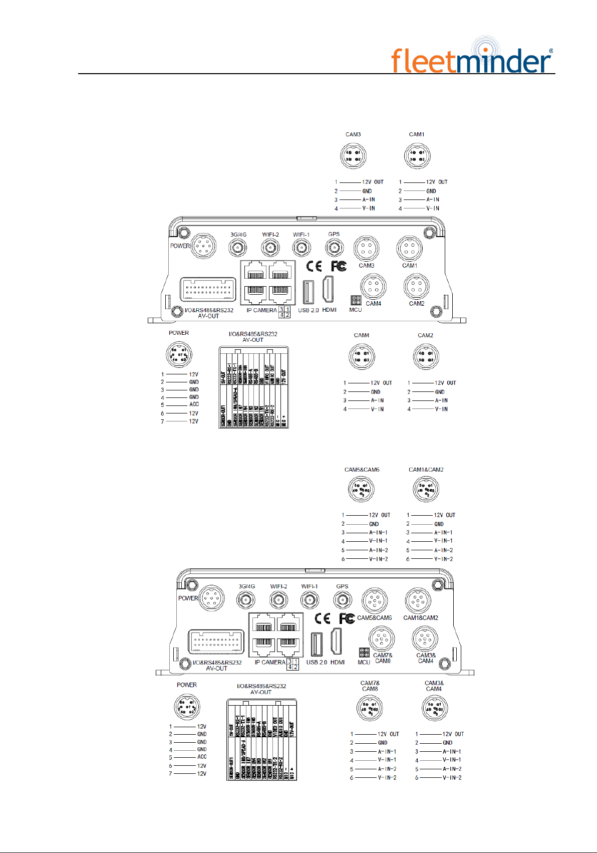
FM MDVR-IP4 Interface Diagram
FM MDVR-IP8 Interface Diagram:

- 8 -
4. Introduction to Main Keys of Your Remote Control
登陆(LOGIN)
Login
在录像机设有密码时,按下 LOGIN 键可输入密码。由于系统没有恢复和复位功
能,请切记密码。
When the recorder is set with a password, press the Login key to input your password.
As the system is not provided with
recover and reset features, always keep your
password in mind.
INFO key 信息查看
Check information
四画面分割键
Quad View key
数字键 1,2,3,4
Number key 1, 2, 3, 4
在监视画面下,用于四画面和单画面之间的切换;按下画面分割键显示 4画面,
如果是按下数字 1/2/3/4 那相应的显示通道 1—通道 2—通道 3—通道 4
On the monitoring interface, used to switch between quad view and single view; press
the Quad View key to display 4 screens. You can press number 1/2/3/4 to display
channel 1, channel 2, channel 3 and channel respectively.
退出(RETURN)
Return key
返回上一层子菜单,最终退出设置菜单并退出到监视画面
Return to the previous menu, and finally exit from the setup menu to the monitoring
interface

- 9 -
暂停/单步
PAUSE/STEP key
回放图像资料时的暂停播放和单步放键,每按一次可以播放一步,按下放像键恢
复正常播放速度
Used to pause playing or play images at a single step. Press the key again to recover
normal play speed
帧放键(FRAME)
Frame key Press this key to play a video in a frame rate
播放(PLAY)
Play key
开始播放键(搜索到录像文件且选中后,按下此键就可以播放)
Press this key to start playing (search the video file to be played and select, then press
the key to play it)
快进(FWD)
FWD key
回放录像资料时的快进键,有四档:2X,4X,8X,16X
Forward key in four grades: 2X,4X,8X,16X
快退键(REW)
REW key
回放录像资料时的快进键,有四档:2X,4X,8X,16X
Rewind key in four grades: 2X,4X,8X,16X
NEXT key 播放过程中翻到下一页/下个文件
Page down or roll to the next file
PREV key 播放过程中翻到上一页/上个文件
Page up or roll to the previous file
云台功能键
PTZ key
自动、预置、调用、变倍+、变倍-、调焦+、调焦-、光圈+、光圈-、PTZ、
PRESET、RECALL、BRUSH
Auto, preset, call, zoom +, zoom -, focus +, focus -, aperture +, aperture -
, PTZ,
PRESET, RECALL, BRUSH
F1, F2, F3 F1 是功能测试键
F1 is a key to start functional test

- 10
II. Device and Installation
1. Installation
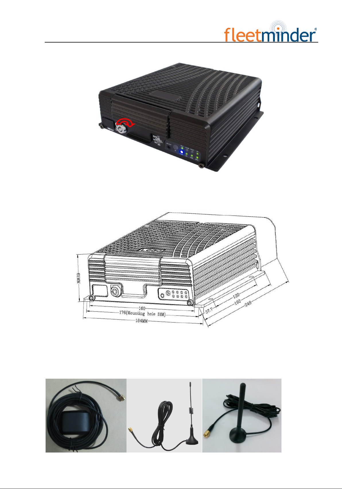
Step 1: Open the protective cover
Turn the electric lock located on the front panel anti-clockwise to unlock it and open the protective cover.
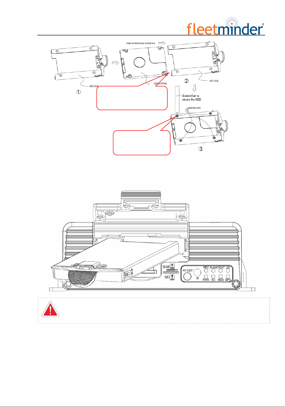
Step 2: Prepare the HDD
Insert the prepared HDD into the HDD box and fix it.
As indicated on the panel, turn the
electric lock anti-clockwise to unlock it
and open the protective cover
Open the protective cover
- 11
Step 3: Insert the HDD
Slowly insert the machined HDD by aligning with the HDD box until you hear a "click" sound.
Take the HDD out of its box by holding the box handle and then pull it out, as shown in the
figure:
Insert 2.5" HDD into its box
Fix it with 4 screws

- 12
Step 4: Install SIM and SD cards
As indicated on the panel, install SIM card and SD card into its respective place. According to the device's
communication configuration, install the related SIM card, such as WCDMA (China Unicom), EVDO (China
Telecom) or TD-SCDMA (China Mobile) in 3G version, as well as TDD-LTE or FDD-LTE in 4G version. The
SD card is mainly used to back up video files when the HDD is exceptional (the SD card is located on the
communication board and only present in models with 3G/4G module supported).
Step 5: Lock the electric lock
After all units are installed, close the protective cover, and then turn the electric lock clockwise to lock it;
- 13
otherwise, the device cannot be powered on.
Step 6: Install the mainframe
According to indicated MDVR mounting hole size, install the device in a proper place of the vehicle.
Step 7: Install GPS, 3G/4G, WiFi antenna
As shown in the following figure, connect GPS, 3G/4G and WiFi antenna to corresponding interface on the
rear panel of the MDVR and keep wires well arranged to protect the signal from external interference.

- 14
GPS 3G 4G
Step8:接电源线
Step 8: Connect the power cord
Connect the air power cord to 6PIN power input interface on the rear panel of the MDVR (If it is in white,
the 6pin cable shall be connected with an adapter), while the red and black cables are directly connected to the
battery of the vehicle, i.e. positive terminal and negative terminal respectively. The yellow cable is connected to
ACC, the vehicle control circuit switch (used to start the vehicle motor). The unit will be enabled automatically
when the car key is enabled and disabled when the key is disabled.
When the device is not installed in a vehicle (such as monitoring systems in bus station, logistic transfer) or
under test, you can use a switching power above DC12V-5A to supply the mainframe. In this case, twist the red
and yellow cables as a cable to connect it to the positive terminal, while the black one is connected to the negative
terminal separately.
。
It is suggested that the vehicle mounted machine be directly powered from positive and negative terminals of the
battery cell, or led from the mains power at the fuse without use of ground strap, which may influence normal
operation of the mainframe due to negative pulse; The power cable used for positive and negative terminals shall
have diameter of φ1.5mm or above.
This terminal is connected to
the power interface on the rear
panel of the MDVR
Before connecting, check that the voltage ranges from 8V to
36V. If not, the device will be suspended.
Connect it to an air adapter
before connecting to the
power interface on the rear
panel of the MDVR
- 15
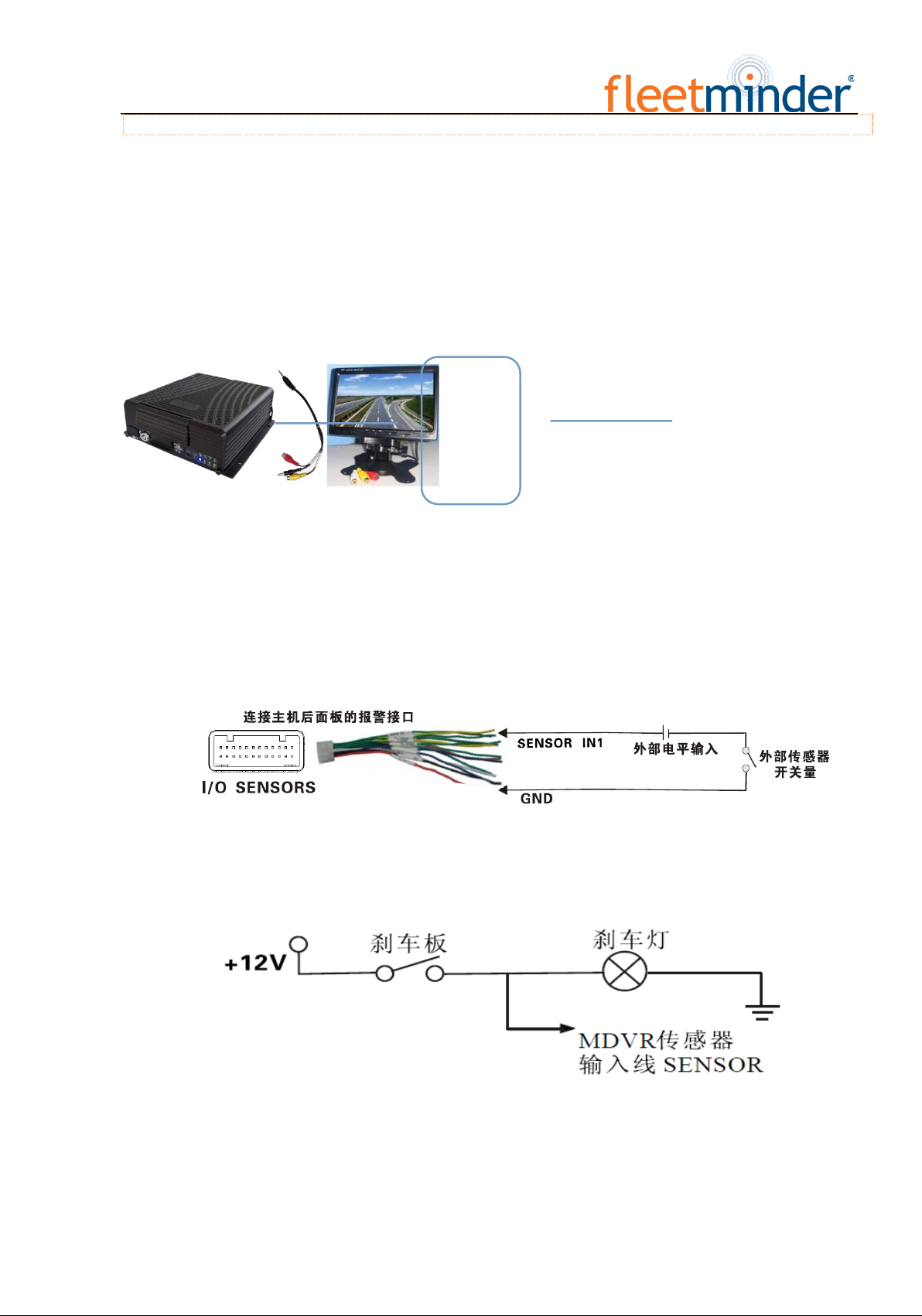
Step 9: Connect the display output unit
This product supports one HDMI and two CVBS video outputs (one is φ3.5 Phone Jack on the front panel,
and the other is 24PIN connector). A customer can connect to the display unit according actual conditions.
Connect the 3-in-1 terminal of the supplied 4pin-AV output cable to the φ3.5 Phone Jack on the front panel, and
the other terminal to the display unit.
Step 10: Alarm input and output cable
A: Sensor input alarm cable
Connect the external sensor to set with alarm feature to 8 external alarm input ports of the I/O sensor on the
rear panel of the MDVR. The external alarm inputs shall be connected to related sensor switching units, such as
door magnet power, emergency switch, turn signal switch and brake light, as shown in the following figure.
For example: the following block diagram shows that high level is detected when the brake pad is stepped
down; otherwise, low level will be detected. Thus, braking operation may trigger device alarm.
B: Over-speed alarm cable
a: If a speed is acquired from GPS, requiring normal GPS signal, the alarm feature can be enabled by simply
configuring settings via Setup menu -> Alarm -> Speed.
Table of contents
Other Fleetminder DVR manuals


