SC Black Digital NM10 Series User manual

To speak with a trained sales consultant dedicated to serving your region,
contact us at 1-877-5SC-BLACK or visit our website at www.sc-black.com
SC Black is a registered trademark of Supercircuits. Copyright © 2008 Supercircuits, Inc. All rights reserved. www.sc-black.com
Quick Start Guide
NM10 & SM10 Series DVRs
Welcome to the World
of Business Intelligence.
Congratulations on your new SC Black Digital Surveillance Management
System. This guide provides an overview, specications, troubleshooting
information and quick setup of your new system. For more information
visit us at www.sc-black.com.

For order assistance, questions and inquiries, please contact one of our sales consultants at: 1-877-5SC-BLACK or
through email at [email protected], or please feel free to browse our website at www.sc-black.com.
SC Black is a registered trademark of Supercircuits. Copyright © 2008 Supercircuits, Inc. All rights reserved. www.sc-black.com
Quick Start Guide
NM10 & SM10 Series DVRs
1. Getting Started
This Quick Start Guide explains the installation
involved with your DVR. For additional information or
support, contact a customer service representative.
2. Unpacking the Contents
The following should be included with the DVR. Please
inspect these and the DVR while unpacking.
• Quick Start Guide
• Surge Protection Notice
• Recovery DVD
• Application CD
• Nero CD
• Mouse/Keyboard
• Power Cord
• Video Input Cables (NM10 only)
• Audio Input Cables (NM10 only)
• PTZ Control Cable (NM10 only)
• RS232 PTZ Control Cable (NM10 only)
3. Choose a Proper Location
Select a location for the DVR that meets the following
requirements. Notice: Excessive heat can shorten the
life of electronics.
• Adequate ventilation to avoid excessive heat
• Uninterrupted Power Supply (UPS)
• Moisture-free environment
• A place away from direct sunlight
• An area with minimal dust or debris
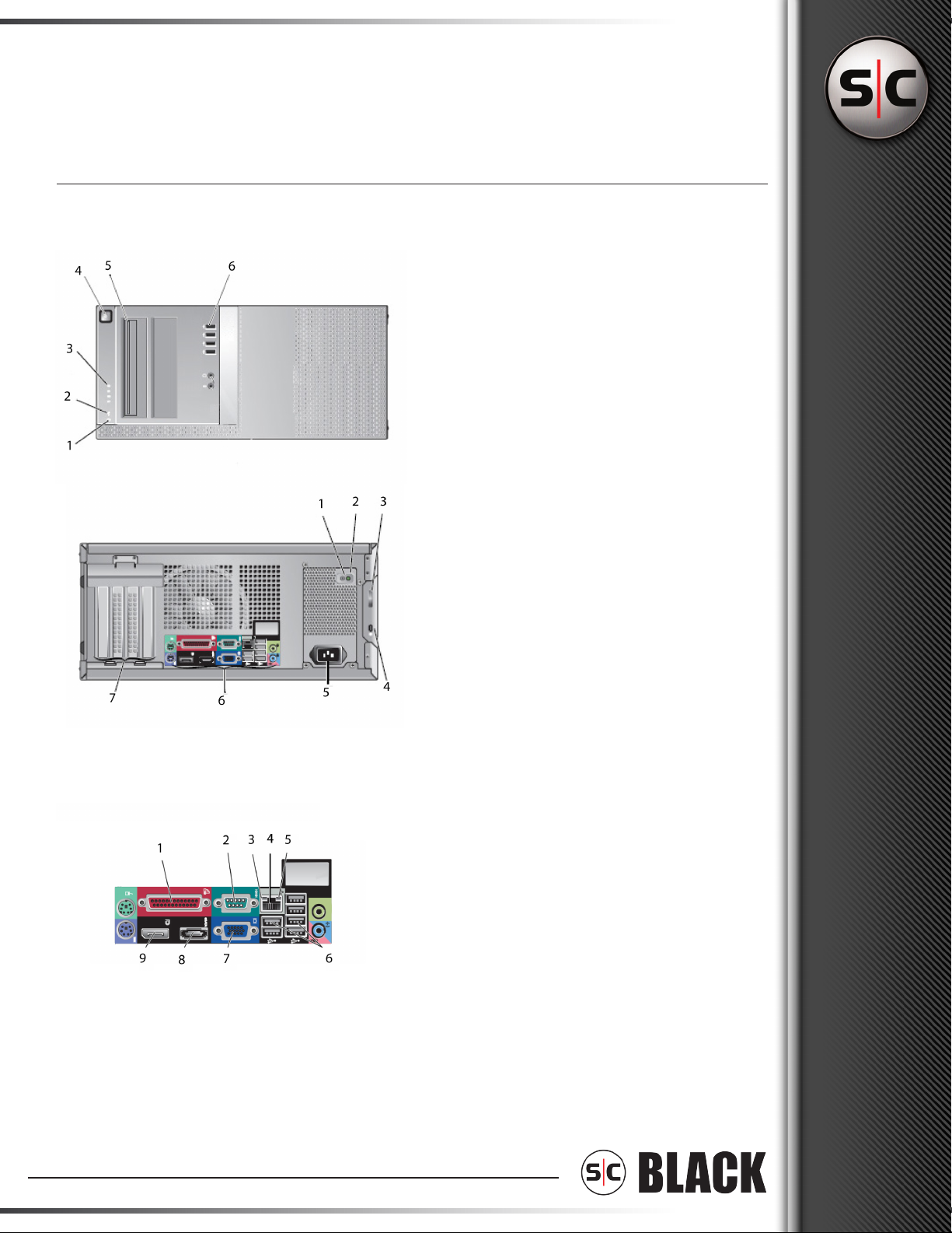
4. Site Installation
Hardware Setup – Connect all input devices and
external peripherals to the DVR. Please refer to the
diagrams in regard to what should be connected to
your DVR.
• Indoor & Outdoor Camera(s)
• VGA monitor
• Spot Monitor Output - Optional (NM10 only)
• PTZ Camera(s) - Optional
• Audio in - Optional (NM10 only)
• Speakers - Optional
• Ethernet
• Mouse
• Keyboard
• Relays and I/O - Optional (NM10 only)
• Cash Register (RS232) - Optional
• Power Cord
Notice: For proper indoor and outdoor cameras an in-
line surge suppressor or equivalent should be used to
reduce exposure to surges and lightning strikes.
Getting Started

For order assistance, questions and inquiries, please contact one of our sales consultants at: 1-877-5SC-BLACK or
through email at [email protected], or please feel free to browse our website at www.sc-black.com.
S|C Black is a registered trademark of Supercircuits. Copyright © 2008 Supercircuits, Inc. All rights reserved. www.sc-black.com
Quick Start Guide
NM10 & SM10 Series DVRs
About Your System
1. Hard Drive Activity Light
2. Link Integrity Light
3. Diagnostic Lights
4. Power Button, Power Lights
5. Slot Load Optical Drive
6. USB 2.0 Connectors (4)
Front View
1. Power Supply Built-in Self-Test Button
2. Power Supply Status Light
3. Cover-release latch and padlock ring
4. Security Cable Slot
5. Power Cable Connector
6. Back-panel Connectors
7. Expansion-card Slots
1. Parallel Connector
2. Serial Connector
3. Link Integrity Light
4. Network Adapter Connector
5. Network Activity Light
6. USB 2.0 Connectors (6)
7. VGA Connector
8. eSata Connector
9. DisplayPort Connector
Back View
Back Panel Connectors

For order assistance, questions and inquiries, please contact one of our sales consultants at: 1-877-5SC-BLACK or
through email at [email protected], or please feel free to browse our website at www.sc-black.com.
SC Black is a registered trademark of Supercircuits. Copyright © 2008 Supercircuits, Inc. All rights reserved. www.sc-black.com
Quick Start Guide
NM10 & SM10 Series DVRs
Setting Up Your System
1. Place unit into the installed rackmount tray
2. Connect the monitor using a VGA cable
3. Connect a USB device, such as a keyboard or mouse.
4. Connect the network cable
5. Connect the power cable(s).
6. Connect the video cable(s) to the video capture board.
®
www.digiop.com
Setting Up Your System
1. Place unit into the installed rackmount tray.
2. Connect the Monitor using a VGA cable
4. Connect the network cable.
6. Connect the video cable(s) to the video capture board.
3. Connect a USB device, such as
a keyboard or mouse.
5. Connect the power cable(s).
7. Close the front panel of the rack tray.
S:V1.011410
Copyright ©2009 DIGIOP Technologies • Indianapolis, IN • p: 800.968.3606 • f: 317.663.2077 • www.digiop.com
DIGIOP is a registered trademark of DIGIOP Technologies. All rights reserved.
• Video In 9-16 / Audio In 3-4 (port B)
• Video In 1-8 / Audio In 1-2 (port A)
H480
Optional
B
A
This manual suits for next models
1
Other SC Black Digital DVR manuals