FLENDER AIQ EMBEDDED User manual
Operating instructions A6230-01en
Edition 09/2022
AIQ EMBEDDED

Original operating instructions
A6230-01
Edition 09/2022
Copyright (©2022 Flender GmbH)
V1
20/10/2022
10:02:22

A6230-01en Edition 09/2022 3
Table of contents
1 Introduction.................................................................................................................................................9
1.1 Legal information .......................................................................................................................9
1.2 General information .................................................................................................................10
1.2.1 Gender .....................................................................................................................................10
1.2.2 Copyright..................................................................................................................................10
1.2.3 Purpose of these instructions...................................................................................................11
1.2.4 Warranty ..................................................................................................................................11
2 Safety information ....................................................................................................................................13
2.1 Intended use ............................................................................................................................13
2.2 Application limits ......................................................................................................................13
2.3 Reasonably foreseeable misuse..............................................................................................13
2.3.1 Prohibited application...............................................................................................................14
2.4 Network and IT security ...........................................................................................................14
2.5 The five safety rules.................................................................................................................14
3 Description................................................................................................................................................15
3.1 Description of the device..........................................................................................................15
3.2 Device overview.......................................................................................................................15
3.3 Operating elements and indicators ..........................................................................................16
4 Application planning ................................................................................................................................19
4.1 Scope of delivery .....................................................................................................................19
5 Assembly...................................................................................................................................................21
5.1 General notes regarding assembly ..........................................................................................21
5.2 Mounting on the gear unit ........................................................................................................21
5.3 Connecting the device .............................................................................................................23
5.3.1 Note on connecting the device.................................................................................................23
5.3.2 Electrical connection ................................................................................................................23
6 Commissioning.........................................................................................................................................27
6.1 General notes on commissioning.............................................................................................27
6.2 Putting the device into operation..............................................................................................27
7 Operator control .......................................................................................................................................29

Table of contents
4 Edition 09/2022 A6230-01en
7.1 Programming speed-dependent vibration monitoring ..............................................................29
7.2 Switching on Bluetooth pairing mode.......................................................................................29
7.3 PIN & device RESET ...............................................................................................................29
7.4 Warning and messages ...........................................................................................................30
7.5 Maintenance management ......................................................................................................30
7.6 Connectivity .............................................................................................................................30
7.6.1 WiFi connection .......................................................................................................................30
7.6.2 Smartphone app ......................................................................................................................31
8 Maintenance..............................................................................................................................................33
8.1 Maintenance, servicing ............................................................................................................33
8.2 Error detection and troubleshooting.........................................................................................33
9 Service & Support.....................................................................................................................................35
9.1 Contact.....................................................................................................................................35
10 Disposal.....................................................................................................................................................37
10.1 Disposal instructions for electronic equipment.........................................................................37
A Declaration of conformity ........................................................................................................................39
A.1 EU Declaration of Conformity ..................................................................................................39
B Technical specifications ..........................................................................................................................41
B.1 Rating plate..............................................................................................................................41
B.2 Electrical specifications............................................................................................................41
B.3 Communication interfaces .......................................................................................................41
B.4 Environmental data ..................................................................................................................41
B.5 Housing....................................................................................................................................42
B.6 Inputs and outputs ...................................................................................................................42
B.7 Sensor technology ...................................................................................................................44
B.8 Battery......................................................................................................................................44
Index ..........................................................................................................................................................45

A6230-01en Edition 09/2022 5
List of figures
Figure3-1 Connectors and sensors ............................................................................................................15
Figure3-2 LED indicators............................................................................................................................16
Figure4-1 Exploded drawing of the AIQ EMBEDDED ................................................................................19
Figure5-1 Seal seat ....................................................................................................................................21
Figure5-2 Device surface O-ring.................................................................................................................22
Figure5-3 Screws for upper housing section ..............................................................................................22
Figure5-4 Seal upper section......................................................................................................................23
Figure5-5 Electrical connection, connection pin assignment......................................................................24
Figure5-6 Connection example: Analogue output ......................................................................................24
Figure5-7 Connection example: Digital switching output............................................................................25
Figure7-1 Device connection......................................................................................................................31
FigureB-1 Rating plate ................................................................................................................................41

List of figures
6 Edition 09/2022 A6230-01en

A6230-01en Edition 09/2022 7
List of tables
Table3-1 Connector description ................................................................................................................16
Table5-1 Table for electrical connection, connection pin assignment.......................................................24
Table8-1 Troubleshooting table.................................................................................................................33
TableB-1 Electrical specifications ..............................................................................................................41
TableB-2 Communication interfaces..........................................................................................................41
TableB-3 Environmental data ....................................................................................................................41
TableB-4 Housing ......................................................................................................................................42
TableB-5 Digital outputs (DO1/DO2) .........................................................................................................42
TableB-6 Digital output (DO3)....................................................................................................................43
TableB-7 Analogue outputs (AO1/AO2) ....................................................................................................43
TableB-8 Input (IN 1) .................................................................................................................................43
TableB-9 Sensor technology......................................................................................................................44
TableB-10 Battery........................................................................................................................................44

List of tables
8 Edition 09/2022 A6230-01en
A6230-01en Edition 09/2022 9
Introduction 1
1.1 Legal information1.1 Legal information
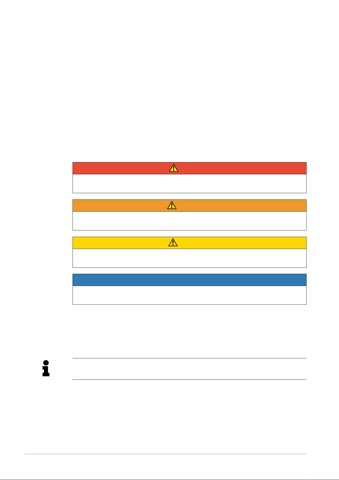
Warning system
These instructions contain information you must observe for your own personal safety as
well as to avoid damage to property and persons. The information regarding your personal
safety is highlighted with a warning triangle. Information exclusively regarding property dam-
age alone is not marked with a warning triangle. Depending on the hazard class, the warn-
ings shall be depicted as follows, in descending order.
DANGER
means that death or severe physical injury will occur if the relevant precautionary meas-
ures are not taken.
WARNING
means that death or severe physical injury may occur if the relevant precautionary meas-
ures are not taken.
CAUTION
means that mild physical injury may occur if the relevant precautionary measures are not
taken.
NOTICE
means that damage to property may occur if the relevant precautionary measures are not
taken.
If multiple hazard classes come into play, the warning for the highest level in question shall
always be used. If a warning containing the warning triangle warns of harm to individuals, the
same warning may also include a warning regarding damage to property.
Information
Information
Information offers additional notes, assistance and tips for handling the product.

Introduction
1.2 General information
10 Edition 09/2022 A6230-01en
Qualified personnel
The product/system associated with this documentation may only be used by qualified per-
sonnel trained to perform the relevant tasks, taking into account the associated documenta-
tion for the relevant tasks, particularly the safety information and warnings included therein.
Due to their qualification and experience, qualified personnel are capable of detecting risks
and avoiding potential hazards when dealing with these products/systems.
Intended use of Flender products
Please note the following:
WARNING
Flender products are only suitable for the uses set out in the catalogue and associated
technical documentation. If third-party products and components are used, these must be
recommended and/or authorised by Flender. Safe and flawless operation of the products
requires proper transport, proper storage, setup, assembly, installation, commissioning,
operation and maintenance. The permissible environmental conditions must be adhered
to. Instructions in the associated documentation must be followed.
Trademarks
All designations marked with the trademark symbol ® are registered trademarks of Flender
GmbH. Other designations in this document may be trademarks whose use by third parties
for their own purposes may violate the rights of the owner.
Liability disclaimer
We have assessed the contents of these instructions for compliance with the hardware and
software described. However, deviations cannot be ruled out, so we are unable to accept li-
ability for full compliance. The details in these instructions are regularly reviewed and neces-
sary corrections are contained in subsequent editions.
1.2 General information1.2 General information
1.2.1 Gender1.2 General information
When genders are mentioned, all known genders are implied and addressed equally.
1.2.2 Copyright1.2 General information
The copyright of these instructions is held by Flender.
Without the authorisation of Flender, these instructions may not be used wholly or in parts,
translated into other languages or made available to third parties.
If you have any technical queries, please contact the Customer Services address.

Introduction
1.2 General information
A6230-01en Edition 09/2022 11
1.2.3 Purpose of these instructions1.2 General information
The AIQ EMBEDDED described in these instructions will be referred to below simply as the
“device”.
To avoid personal injury or property damage, follow the safety information and notices in
these instructions.
Read and carefully observe the instructions supplied with the device before connecting and
operating the device. The device may only be used on approved Flender gear units. You can
find the complete instructions for the device on the Internet at: www.flender.com
(www.flender.com)
For fault-free operation, carefully observe the information in the instructions and adhere to
the specifications.
1.2.4 Warranty1.2 General information
In the event of damage or consequential damage resulting from the direct or indirect use of
the documentation, the product or the software, Flender GmbH shall only be liable in the
event of intent or gross negligence.
Failure to observe the instructions will result in the loss of warranty claims or claims for dam-
ages.

Introduction
1.2 General information
12 Edition 09/2022 A6230-01en

A6230-01en Edition 09/2022 13
Safety information 2
2.1 Intended use2.1 Intended use
The device is intended for use in a commercial or industrial environment as specified in
these instructions. The device is supplied fully assembled with a Flender gear unit.
For safe operation, observe the information and notes in these instructions as well as the in-
formation on the rating plate. Otherwise, the device may be permanently damaged.
If the device is not used as intended, Flender accepts no liability. The following applications
are considered as intended uses:
• Use in the commercial or industrial sector
• Mounting in or on Flender gear units
• Acquiring digital and analogue data of the gear unit
• Synchronising data with the Flender-Cloud (AIQ Inside Portal)
2.2 Application limits2.2 Application limits
Use, limits, areas of application
• The device complies with the relevant regulations and European directives.
• Do not use the device for safety-relevant tasks and critical switching operations!
• Only use the device within the limits and areas of application. The limits and areas of ap-
plication are specified in the technical data and in the instructions.
• Improper or non-intended use can lead to malfunctions of the device or undesirable con-
sequents when using the device.
• Using the device in a way that is prohibited may result in personal injury or death.
• The device may only be installed, configured and serviced by qualified electricians who
have been trained to do so in accordance with the applicable relevant regulations.
• The external 24VDC supply voltage for this device must be generated and supplied in
accordance with the criteria for safe extra-low voltage (SELV/PELV).
2.3 Reasonably foreseeable misuse2.3 Reasonably foreseeable misuse
The following applications are examples of non-intended use or suspected misuse. Applica-
tions that are not permitted:
• Operating the device outside of the specification
• Connecting sensors other than those that were supplied
• Operation on non-approved gear units
• Operation in areas other than those approved
• Connecting actuators that do not comply with the technical specification
• Non-observance of the specifications for electrical connection and mechanical mounting
• Fastening using unsuitable fastening screws and tightening torques

Safety information
2.3 Reasonably foreseeable misuse
14 Edition 09/2022 A6230-01en
• Application in all areas other than those approved
• Use with PG-based oils (polyglycols)
2.3.1 Prohibited application2.3 Reasonably foreseeable misuse
The following applications are prohibited:
• Use in potentially explosive atmospheres as well as in Ex-protected areas
• Under water
• The use for safety-relevant tasks in the sense of personal protection or as a guard ac-
cording to DINEN13849-1
2.4 Network and IT security2.4 Network and IT security
With the increased networking of machines and industrial systems, the danger of cyberat-
tacks is also increasing. Therefore, the devices that are connected to a network via WiFi or
Ethernet are at risk of unwanted or unauthorised access from the network.
• Carefully observe the basic rules for network security.
• Make provision for appropriate protective measures.
• Protect the network that the device is connected to.
• Restrict network access to the device.
• Restrict access to the device (refer to chapter PIN & device RESET (Page29)).
2.5 The five safety rules2.5 The five safety rules
In order to protect yourself and prevent any damage to property, always observe the safety
relevant information and the following five safety rules (as per EN50110-1 "Working on isol-
ated equipment") when working on electrical components of the plant.
Prior to starting work on the machine, follow the safety rules listed below:
1. Disconnect
Also disconnect auxiliary circuits such as the anti-condensation heater
2. Safeguard against restart
3. Ensure that the system is de-energised
4. Earth and short circuit
5. Cover or cordon off adjacent live parts
When all the work is complete, cancel the safety measures in the reverse sequence.
A6230-01en Edition 09/2022 15
Description 3
3.1 Description of the device3.1 Description of the device
The device captures diverse information and measured values pertaining to the operating
condition of the Flender gear unit and transfers them to the (signal) outputs of the higher-
level controller (PLC).
In addition, this telemetry and diagnostic data can be transmitted to theFlender Portal AIQ In-
side via WiFi.
The device has one digital input, two digital outputs, two analogue outputs and one digital ta-
chometer output for settings and data transfer to the higher-level controller. The device re-
members the time thanks to a built-in battery. The configured settings are retained even if
the battery is empty.
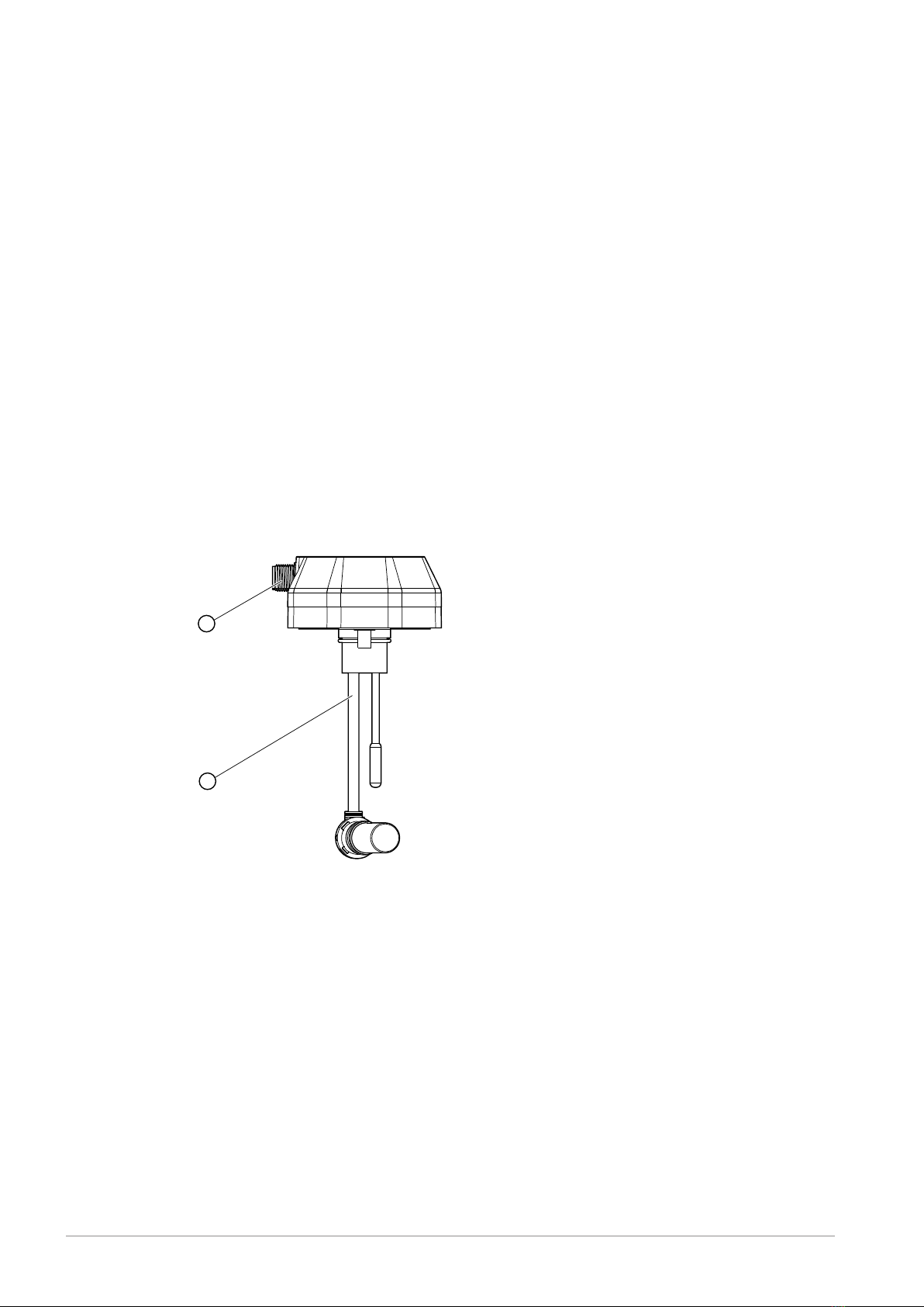
3.2 Device overview3.2 Device overview
Figure3-1:Connectors and sensors
1 Connection 2 Sensor area: Oil sump temperature sensor
and tachometer sensor
Connection
Connect the device via an M12 sensor or actuator cable connection. The connector pin as-
signment of the device can be found in the following table.

Description
3.3 Operating elements and indicators
16 Edition 09/2022 A6230-01en
Connector pin assignment No. Signal
Front view of the connector
1 Analog out 1
2 +24VDC
3 Analog out 2
4 Digital out 1
5 RPM out
6 Digital out 2
7 GND
8 Digital in 1
Table3-1: Connector description
Sensor area: Oil sump temperature sensor and tachometer sensor
The sensors that are already connected are mounted inside the gear unit.
The cable lengths are pre-determined and different versions can be ordered depending on
the gear unit size. Adjusting the length after this is not possible.
3.3 Operating elements and indicators3.3 Operating elements and indicators
Figure3-2:LED indicators
1 POWER LED 2 STATUS LED
3 LINK LED
POWER LED
1Hz flashing: Start process / Update active / Initialisation
3Hz flashing: RESET process active
Permanently lit up: Device ready for operation
STATUS LED
Permanently lit up: Error-free analyses

Description
3.3 Operating elements and indicators
A6230-01en Edition 09/2022 17
1Hz flashing: Check gear unit status, warning threshold reached
3Hz flashing: Alarm, vibration values outside the parameters
LINK LED
Permanently lit up: Active WiFi network connection
1Hz flashing: Active Bluetooth connection with smartphone
Bluetooth pairing mode
When Bluetooth pairing mode is activated, the LEDs flash one after the other in a clockwise
direction.

Description
3.3 Operating elements and indicators
18 Edition 09/2022 A6230-01en

A6230-01en Edition 09/2022 19
Application planning 4
4.1 Scope of delivery4.1 Scope of delivery
Figure4-1:Exploded drawing of the AIQ EMBEDDED
The device is pre-configured for the gear unit and prepared for assembly.
The components supplied are:
• Device with the associated mounting kit
– 2x fastening screws (M6x14)
– 1x seal for sealing the sensor housing halves
– 1x seal for sealing the sensor on the gear unit
– 3x housing screws (2.5x7mm)
– 1x sticker for sealing the screw surfaces
– 2x M6x14 cylinder-head screws DIN6912
• 2m connection cable M12x8pol
Delivered state
The device is supplied configured for a specific Flender gear unit and so cannot be used on
its own.

Application planning
4.1 Scope of delivery
20 Edition 09/2022 A6230-01en
The device is used to monitor machine-related telemetry data.
Do not use this device on a Flender gear unit other than the one configured.
Use the device only in combination with the gear-unit-specific sensor mounting material.
Table of contents
Other FLENDER Accessories manuals

Popular Accessories manuals by other brands

RAB Lighting
RAB Lighting Stealth STL200 installation manual

WOOX
WOOX R6073 quick start guide

NeuLog
NeuLog NUL-231 Guide

Leviton
Leviton DECORA ODS10-IDI installation instructions

Playcore
Playcore Colorado Time Systems Championship Start Instruction guide

MTS Systems
MTS Systems Temposonics R-Series Brief instructions


