FLENDER DX2000+ User manual

Operating instructions S6300-01en
Edition 10/2022
DX2000+

Original operating instructions
S6300-01
Edition 10/2022
Copyright (©2022 Flender GmbH)
V3
19/10/2022
15:23:18

S6300-01en Edition 10/2022 3
Table of contents
1 Introduction...............................................................................................................................................11
1.1 Legal information .....................................................................................................................11
1.2 Purpose of these instructions...................................................................................................12
1.3 Information for the operator .....................................................................................................12
1.4 Copyright..................................................................................................................................13
2 Safety information ....................................................................................................................................15
2.1 Security notes ..........................................................................................................................15
2.2 The five safety rules.................................................................................................................15
2.3 General information .................................................................................................................15
2.4 Intended use ............................................................................................................................16
2.5 Reasonably foreseeable misuse..............................................................................................16
2.6 Residual risk ............................................................................................................................17
2.7 Description of the guards .........................................................................................................17
2.8 Markings and signs ..................................................................................................................17
2.9 Safety information for the personnel ........................................................................................18
2.10 Safety instructions for maintenance personnel ........................................................................18
2.11 Additional safety information for maintenance .........................................................................19
2.12 Notes on special types of hazards ...........................................................................................19
2.12.1 Electrics ...................................................................................................................................19
2.12.2 Components that can be destroyed by electrostatic discharge (ESD).....................................20
2.12.3 Noise........................................................................................................................................20
2.12.4 Vibration...................................................................................................................................21
2.12.5 IT security ................................................................................................................................21
3 Description................................................................................................................................................23
3.1 Product description ..................................................................................................................23
3.2 CMS DX2000+ assembly units ................................................................................................23
3.3 Sensors....................................................................................................................................26
3.3.1 Overview of compatible sensors ..............................................................................................26
3.3.2 IEPE accelerometers ...............................................................................................................27
3.3.3 Temperature sensors...............................................................................................................27
3.3.4 Current and voltage sensors....................................................................................................27

Table of contents
4 Edition 10/2022 S6300-01en
3.3.5 Speed sensor...........................................................................................................................27
3.4 Interfaces .................................................................................................................................28
3.4.1 Ethernet ...................................................................................................................................28
3.4.2 Ethernet telegram ....................................................................................................................29
3.4.3 Pin assignment of system interface for temperature modules .................................................35
3.5 Electromagnetic compatibility ..................................................................................................35
4 Application planning ................................................................................................................................37
4.1 Transport..................................................................................................................................37
4.2 Storage ....................................................................................................................................37
4.3 Application planning.................................................................................................................38
4.3.1 Scope of delivery .....................................................................................................................38
4.3.2 Unpacking and checking the delivery ......................................................................................38
4.3.3 Location of use.........................................................................................................................38
5 Assembly...................................................................................................................................................41
5.1 Introduction ..............................................................................................................................41
5.2 Assembly of the DX2000+ control cabinet and DX site server ................................................ 41
5.3 Mounting the CMS DX2000+ ...................................................................................................42
5.3.1 Electrical installation ................................................................................................................42
5.3.2 Assembling the sensors...........................................................................................................43
5.3.2.1 Safety information for mounting the sensors ...........................................................................43
5.3.2.2 Fastening vibration accelerometers .........................................................................................44
5.3.2.3 Fastening speed sensors.........................................................................................................44
5.3.2.4 Installing the displacement sensor...........................................................................................44
5.3.3 Completing the mounting work ................................................................................................46
5.4 Safety guidelines......................................................................................................................46
5.5 Electrical connection ................................................................................................................46
5.5.1 Safety information for electrical connection .............................................................................46
5.5.2 Requirements for cables ..........................................................................................................47
5.5.3 Connecting the cable shield.....................................................................................................48
5.5.4 Wiring.......................................................................................................................................49
5.5.5 Connection of DX2000+ control cabinet to the DX site server.................................................51
5.6 Dismantling ..............................................................................................................................51
6 Commissioning.........................................................................................................................................53
6.1 Commissioning ........................................................................................................................53
7 Operator control .......................................................................................................................................55
7.1 Introduction ..............................................................................................................................55

Table of contents
S6300-01en Edition 10/2022 5
7.2 Safe operator control ...............................................................................................................55
7.3 Switching on and off, operation................................................................................................56
7.4 Faults .......................................................................................................................................57
8 Maintenance..............................................................................................................................................59
8.1 Introduction ..............................................................................................................................59
8.2 Care of the DX2000+ control cabinet or DX site server ...........................................................60
8.3 Preparations for repair and maintenance work ........................................................................61
8.4 Safely maintaining electrical equipment...................................................................................61
8.5 Testing safety equipment on the control cabinet .....................................................................62
8.6 Maintenance schedule .............................................................................................................62
9 Service & Support.....................................................................................................................................65
9.1 Contact.....................................................................................................................................65
9.2 Technical return address .........................................................................................................65
10 Disposal.....................................................................................................................................................67
10.1 Plastics.....................................................................................................................................67
10.2 Metals ......................................................................................................................................67
10.3 Electrical and electronic waste.................................................................................................67
10.4 Scrapping.................................................................................................................................67
A Declaration of conformity ........................................................................................................................69
A.1 EU Declaration of Conformity ..................................................................................................69
B Technical specifications ..........................................................................................................................71
B.1 Rating plate..............................................................................................................................71
B.2 Technical data for the DX site server – version: Control cabinet .............................................71
B.3 Technical data for thr DX site server – version: Rack PC 19″..................................................72
B.4 Technical data for the DX2000+ control cabinet ......................................................................72
B.5 Technical data for temperature module ...................................................................................74
B.6 Relevant assumptions..............................................................................................................75
B.7 Environmental conditions.........................................................................................................75
C Annex.........................................................................................................................................................77
C.1 Certificates and approvals .......................................................................................................77
C.2 Software...................................................................................................................................77


S6300-01en Edition 10/2022 7
List of figures
Figure3-1 Condition Monitoring System DX2000+ system design .............................................................23
Figure3-2 Example of the electrical design of the DX2000+ control cabinet ..............................................25
Figure3-3 Example of assembly of the DX2000+ control cabinet...............................................................25
Figure3-4 Example of the electrical structure of the DX site server control cabinet ...................................26
Figure3-5 Industrial Ethernet (on reader side) connection .........................................................................28
Figure3-6 System interface of the temperature model ...............................................................................35
Figure5-1 Installation situation for the displacement sensors.....................................................................45
Figure5-2 Example of assembly of the shield connector, before................................................................48
Figure5-3 Example of assembly of the shield connector, after...................................................................48
Figure5-4 Connection assignment..............................................................................................................49
Figure5-5 Double-deck terminal with example of labelling .........................................................................50
Figure5-6 Establish Ethernet connection....................................................................................................51
Figure7-1 Mains disconnection device (example model) ...........................................................................56
FigureB-1 Rating plate ................................................................................................................................71

List of figures
8 Edition 10/2022 S6300-01en

S6300-01en Edition 10/2022 9
List of tables
Table2-1 Markings.....................................................................................................................................17
Table2-2 Markings.....................................................................................................................................17
Table5-1 Screw fasteners..........................................................................................................................43
Table5-2 Requirements for parameters.....................................................................................................48
Table8-1 Maintenance table......................................................................................................................62
Table8-2 DX site server Rack PC..............................................................................................................63
Table8-3 DX site server IPC......................................................................................................................63
TableB-1 Technical data of the DX site server – version: Control cabinet.................................................71
TableB-2 DX2000+ control cabinet............................................................................................................75
TableB-3 DX site server.............................................................................................................................75
TableC-1 Certificates and approvals..........................................................................................................77
TableC-2 Software .....................................................................................................................................77

List of tables
10 Edition 10/2022 S6300-01en
S6300-01en Edition 10/2022 11
Introduction 1
1.1 Legal information1.1 Legal information
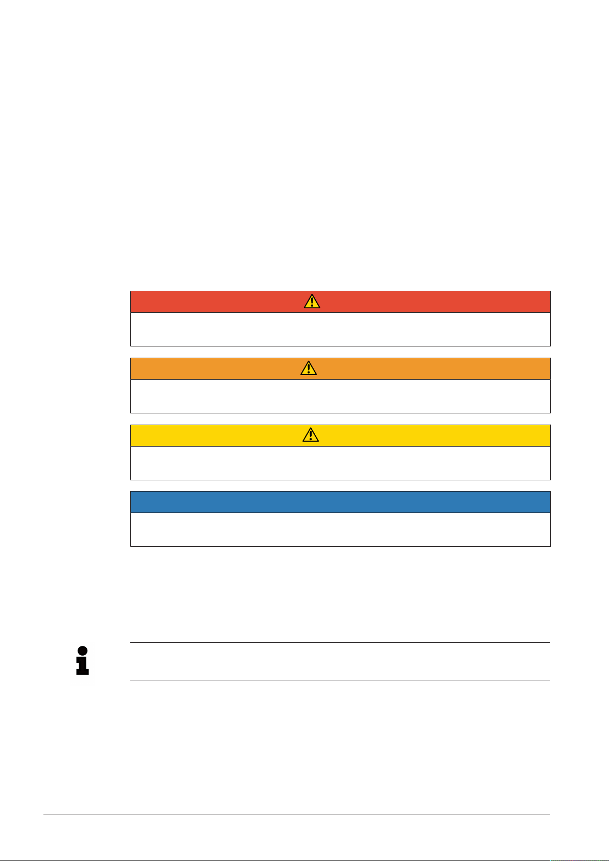
Warning system
These instructions contain information you must observe for your own personal safety as
well as to avoid damage to property and persons. The information regarding your personal
safety is highlighted with a warning triangle. Information exclusively regarding property dam-
age alone is not marked with a warning triangle. Depending on the hazard class, the warn-
ings shall be depicted as follows, in descending order.
DANGER
means that death or severe physical injury will occur if the relevant precautionary meas-
ures are not taken.
WARNING
means that death or severe physical injury may occur if the relevant precautionary meas-
ures are not taken.
CAUTION
means that mild physical injury may occur if the relevant precautionary measures are not
taken.
NOTICE
means that damage to property may occur if the relevant precautionary measures are not
taken.
If multiple hazard classes come into play, the warning for the highest level in question shall
always be used. If a warning containing the warning triangle warns of harm to individuals, the
same warning may also include a warning regarding damage to property.
Information
Information
Information offers additional notes, assistance and tips for handling the product.

Introduction
1.2 Purpose of these instructions
12 Edition 10/2022 S6300-01en
Qualified personnel
The product/system associated with this documentation may only be used by qualified per-
sonnel trained to perform the relevant tasks, taking into account the associated documenta-
tion for the relevant tasks, particularly the safety information and warnings included therein.
Due to their qualification and experience, qualified personnel are capable of detecting risks
and avoiding potential hazards when dealing with these products/systems.
Intended use of Flender products
Please note the following:
WARNING
Flender products are only suitable for the uses set out in the catalogue and associated
technical documentation. If third-party products and components are used, these must be
recommended and/or authorised by Flender. Safe and flawless operation of the products
requires proper transport, proper storage, setup, assembly, installation, commissioning,
operation and maintenance. The permissible environmental conditions must be adhered
to. Instructions in the associated documentation must be followed.
Trademarks
All designations marked with the trademark symbol ® are registered trademarks of Flender
GmbH. Other designations in this document may be trademarks whose use by third parties
for their own purposes may violate the rights of the owner.
Liability disclaimer
We have assessed the contents of these instructions for compliance with the hardware and
software described. However, deviations cannot be ruled out, so we are unable to accept li-
ability for full compliance. The details in these instructions are regularly reviewed and neces-
sary corrections are contained in subsequent editions.
1.2 Purpose of these instructions1.2 Purpose of these instructions
These instructions describe the CMS DX2000+ and provide information about its handling.
Please keep these instructions for later use. Please read these instructions prior to handling
the DX2000+. The instructions should be observed.
1.3 Information for the operator1.3 Information for the operator
These instructions form an essential component of the DX2000+.
Please ensure that all persons working with or on the DX2000+ take note of these instruc-
tions.
Replacement parts must comply with the technical requirements specified by Flender . This
is always guaranteed with original replacement parts.

Introduction
1.4 Copyright
S6300-01en Edition 10/2022 13
If you have any technical queries, please contact Service & Support (Page65).
1.4 Copyright1.4 Copyright
The copyright of these instructions is held by Flender.
Without the authorisation of Flender, these instructions may not be used wholly or in parts for
competitors’ purposes or be given to third parties.
If you have any technical queries, please contact the Customer Services address
(Page65).

Introduction
1.4 Copyright
14 Edition 10/2022 S6300-01en

S6300-01en Edition 10/2022 15
Safety information 2
2.1 Security notes2.1 Security notes
Flender offers products and solutions with industrial security functions, which support the
safe and secure operation of plants, systems, machines and networks.
In order to safeguard plants, systems, machines and networks against cyber threats it is ne-
cessary to implement (and continually maintain) a holistic industrial security concept that cor-
responds to the current state of the art. Flender products and solutions undergo continuous
development in this respect.
Customers are responsible for preventing unauthorised access to their plants, systems, ma-
chines and networks. These systems, machines and components shall be connected to the
company network or the Internet only when and to the extent that this is absolutely neces-
sary and appropriate protective measures (e.g. firewalls and/or network segmentation) shall
be taken.
You can find further information about possible protection measures as part of Industrial Se-
curity in the following international series of standards, for example: IEC62443 "Network and
system security".
Flender products and solutions undergo continuous development in order to make them
even safer. Flender strongly recommends that you regularly implement product updates as
soon as they become available and that you only use the current product versions. Use of
older or no longer supported versions can increase the risk of cyber threats.
2.2 The five safety rules2.2 The five safety rules
In order to protect yourself and prevent any damage to property, always observe the safety
relevant information and the following five safety rules (as per EN50110-1 "Working on isol-
ated equipment") when working on electrical components of the plant.
Prior to starting work on the machine, follow the safety rules listed below:
1. Disconnect
Also disconnect auxiliary circuits such as the anti-condensation heater
2. Safeguard against restart
3. Ensure that the system is de-energised
4. Earth and short circuit
5. Cover or cordon off adjacent live parts
When all the work is complete, cancel the safety measures in the reverse sequence.
2.3 General information2.3 General information
The DX2000+ has been designed and built according to the latest technological develop-
ments and recognised safety rules.
• Only trained and instructed personnel may operate theDX2000+.
• The DX2000+ should only be used for the intended purpose.

Safety information
2.4 Intended use
16 Edition 10/2022 S6300-01en
• Maintenance should be carried out properly.
2.4 Intended use2.4 Intended use
The DX2000+ is intended for industrial, commercial applications and for installation in and on
other operating equipment.
A typical area of application for the system is acquiring analogue and digital sensor signals
from certain components of a drive train and transferring these to the Flender Service
Centre.
The DX2000+ should only be operated within the operating ranges and environmental condi-
tions specified.
Prior to commissioning, you must establish the conformity of the system or machine to the
Supply of Machinery (Safety) Regulations, Electrical Equipment (Safety) Regulations and
Electromagnetic Compatibility Regulations.
Information
Carefully observe and adhere to the specifications in the technical data (Page71).
For intended use, follow the notes described in these instructions:
• Safety
• Operation and control
• Maintenance and repair
Any other use or use beyond this is considered improper. The operator alone is solely liable
for any resulting damage. This also applies to unauthorised modifications to the DX2000+.
2.5 Reasonably foreseeable misuse2.5 Reasonably foreseeable misuse
The following processing methods are considered improper, for example:
• The use and processing of explosive substances.
• Connecting sensors other than those listed in the instructions.
• Operating the DX2000+ in a potentially explosive atmosphere.
• Operating the DX2000+ without fully attached protective devices.
• Use by private users, or users without professional instruction and training.
• Storing explosive or highly flammable substances in the area around the DX2000+.
• If sensors other than those listed in the instructions are used/connected, reliable func-
tioning and protection of the gear unit/drive train cannot be guaranteed.
• Setting up the DX2000+ in unprotected room or halls subject to climatic conditions is not
prohibited.

Safety information
2.6 Residual risk
S6300-01en Edition 10/2022 17
2.6 Residual risk2.6 Residual risk
DANGER
Danger to life due to electric shock
Electric shock results in fatal injuries.
• Prior to starting work, switch off the power supply to the system via the mains discon-
nection device.
• Secure the system against being switched on accidentally.
• Close the mains disconnection device and put up warning signs.
• When working around rotating parts, also press an emergency stop button.
Even if all safety regulations are observed, a residual risk remains when operating the
DX2000+ as described below.
• As the operator you are responsible for ensuring all persons working on and with the
DX2000+ are aware of the residual risks.
• Follow the instructions that prevent residual risks from causing accidents or damage.
During the installation work, it may be necessary to dismantle on-site guards. This creates
various residual risks and potential dangers that every operator must be aware of.
2.7 Description of the guards2.7 Description of the guards
Protective measures
Protective conductor PE and centre conductor N are routed to separate connecting termin-
als.
At each mains connection point, the terminal for the external protective earth system or the
external protective conductor is designated or labelled with the letters PE.
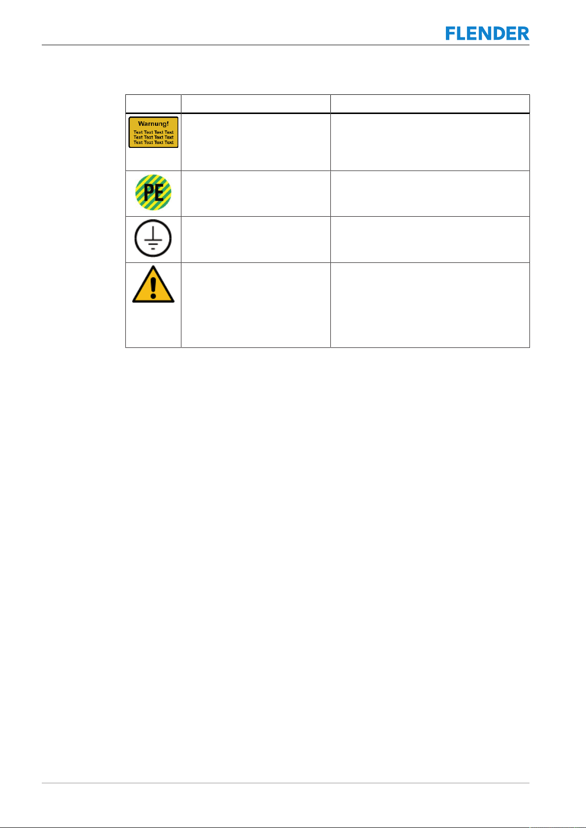
2.8 Markings and signs2.8 Markings and signs
Sign Meaning Attachment location
CMS Local marking Easily legible on the DX2000+ control cabinet
door
Table2-1: Markings
Sign Meaning Attachment location
Warning – hazardous electrical
voltage
On all terminal boxes, control boxes and control
cabinets for low voltage
Safety information
2.9 Safety information for the personnel
18 Edition 10/2022 S6300-01en
Sign Meaning Attachment location
Warning sign:
Voltage is present at the marked
points even when the mains discon-
nection device is switched off!
On the control cabinet
Marking:
Connection point for the external
protective conductor
Protective conductor connection terminal
Marking:
Protective conductor connection
Next to the earthing screws
High
leakage cur-
rent
Warning against high leakage cur-
rent
Protective conductor connection terminal:
Only for higher leakage currents greater than
AC/DC 10mA
Table2-2: Markings
2.9 Safety information for the personnel2.9 Safety information for the personnel
Every person who is assigned to work on or with the DX2000+ must have read and under-
stood these instructions in full.
• Only use the DX2000+ when it is in perfect technical condition and for its intended pur-
pose, in a safety- and hazard-conscious manner and in compliance with these instruc-
tions.
Flender accepts no liability for damage and accidents caused by non-observance of the in-
structions.
• Eliminate all faults immediately.
• Keep the instructions handy on the DX2000+ at all times.
• Only reliable, trained and qualified personnel of the legally permissible minimum age ac-
cording to youth employment protection law may work on the DX2000+.
• Personnel to be trained, instructed or undergoing general training may only work under
the constant supervision of an experienced person.
If any safety-relevant changes occur on the DX2000+:
• Shut down the DX2000+ immediately.
• Secure the DX2000+ in position.
• Report the incident to the responsible office or person.
2.10 Safety instructions for maintenance personnel2.10 Safety instructions for maintenance personnel
Observe the prescribed intervals or those specified in the instructions for recurring tests and
inspections.

Safety information
2.11 Additional safety information for maintenance
S6300-01en Edition 10/2022 19
2.11 Additional safety information for maintenance2.11 Additional safety information for maintenance
Equipment appropriate for the work is required to carry out maintenance work.
• Only carry out work and troubleshooting when the system is voltage-free. Carefully ob-
serve the The five safety rules (Page15) for this.
• As far as necessary, secure the maintenance area with a red and white safety chain and
a warning sign.
• Ensure safe and environmentally friendly disposal of components, operating materials
and auxiliary materials as described in chapter Disposal (Page67).
• In particular, clean any dirt or care products from connections and screw connections
before maintenance, repair or care work.
• Do not stand under suspended loads.
• Attach and secure individual components and larger assemblies to the hoisting gear
carefully during replacement so that the danger they pose is minimised. Only use suit-
able and technically flawless hoisting gear and load lifting attachments with sufficient
load-bearing capacity.
• During maintenance and repair work, tighten loosened screw connections with a torque
spanner according to specification.
2.12 Notes on special types of hazards2.12 Notes on special types of hazards
2.12.1 Electrics2.12 Notes on special types of hazards
Work on the DX2000+ may only be carried out by a qualified electrician or by instructed per-
sonnel under the supervision of a qualified electrician in accordance with the electrotechnical
regulations.
• Before opening the DX2000+ control cabinet, switch it off with the mains disconnection
device.
• Secure the DX2000+ control cabinet and DX site server against being switched on again
using a safety lock.
• Disconnect electrical components from the power supply.
• Only use original fuses with specified current ratings.
• Only use suitable overcurrent guards whose permissible switch-off times comply with the
expected fault or short-circuit current.
• Secure the equipment that has been disconnected against unintentional or automatic re-
connection by taking the following measures:
– Lock away fuses
– Block circuit breaker
• First check that electrical components are not live when they are disconnected. Then in-
sulate neighbouring live components.
• When carrying out repairs, make sure that design features are not changed in a way that
reduces safety. For example, do not use insulation to reduce creepage distances, clear-
ances or distances.
If work is required on live components (only in exceptional circumstances!):

Safety information
2.12 Notes on special types of hazards
20 Edition 10/2022 S6300-01en
• Call in an additional person who can press the emergency stop button or the mains dis-
connection device in an emergency.
• Only use voltage-insulated tools.
Proper earthing of the electrical system must be ensured by protective conductor systems. A
fixed installation is required for a leakage current to earth of PE>3.5mA.
• Check the cables regularly for damage.
• Replace defective cables immediately.
Further information can be found in the Safely maintaining electrical equipment (Page61)
chapter.
2.12.2 Components that can be destroyed by electrostatic discharge (ESD)2.12 Notes on special types of hazards
Electrostatic discharge (ESD) guidelines
Electronic components can be damaged or destroyed by improper handling, transport, stor-
age and shipping.
Pack the electronic components in suitable ESD packaging; e.g. ESD foam, ESD packaging
bags and ESD transport containers.
To protect your equipment from damage, follow the instructions below:
• Avoid physical contact with electronic components.
• If you must carry out essential work on electronic components, wear some of the follow-
ing protective equipment:
– A grounded ESD wrist strap.
– If there is an ESD floor, you can use ESD shoes or ESD shoe grounding strips.
• Do not place electronic components near data terminals, monitors or televisions. Main-
tain a minimum clearance to the screen (>10cm).
• Electronic components should not be brought into contact with electrically insulating ma-
terials such as plastic film, plastic parts, insulating table covers or clothing made of syn-
thetic fibres.
• Place components in contact with ESD-suitable materials, e.g. ESD tables, ESD sur-
faces, ESD packaging.
• Only carry out measurements on the components if one of the following conditions is
met:
– The measuring device is earthed with a protective conductor, for example.
Precise instructions for ESD protection measures are laid out in the applicable standards
and regulations on electrostatic sensitive components.
2.12.3 Noise2.12 Notes on special types of hazards
The A-weighted equivalent continuous sound pressure level at the operator workstations
during normal operation of the DX2000+ is below 80 dB (A).
Table of contents
Other FLENDER Accessories manuals

Popular Accessories manuals by other brands


NeuLog
NeuLog NUL-206 Guide

Aura
Aura ZEN manual

Barbarian Basketball Systems
Barbarian Basketball Systems Titanium Series Assembly instructions and owner's manual

triOS
triOS TpH operating instructions

Lennox EMEA
Lennox EMEA 3C Series installation instructions

Honeywell
Honeywell RPW113A Mounting instruction


