FLENDER N-EUPEX User manual

FLENDER COUPLINGS
N-EUPEX / N-EUPEX DS
Operating Instructions 3100en
Edition 10/2017
A, B, ADS, BDS

21.09.2017 14:39
V6.00

Legal information
Warning notice system
This manual contains notices you have to observe in order to ensure your personal safety, as well as to prevent
damage to property. The notices referring to your personal safety are highlighted in the manual by a safety alert
symbol, notices referring only to property damage have no safety alert symbol. These notices shown below are
graded according to the degree of danger.
DANGER
indicates that death or severe personal injury will result if proper precautions are not taken.
WARNING
indicates that death or severe personal injury may result if proper precautions are not taken.
CAUTION
indicates that minor personal injury can result if proper precautions are not taken.
NOTICE
indicates that property damage can result if proper precautions are not taken.
If more than one degree of danger is present, the warning notice representing the highest degree of danger will be
used. A notice warning of injury to persons with a safety alert symbol may also include a warning relating to property
damage.
Qualified Personnel
The product/system described in this documentation may be operated only by personnel qualified for the specific
task in accordance with the relevant documentation, in particular its warning notices and safety instructions. Qualified
personnel are those who, based on their training and experience, are capable of identifying risks and avoiding
potential hazards when working with these products/systems.
Proper use of Flender products
Note the following:
WARNING
Flender products may only be used for the applications described in the catalog and in the relevant technical
documentation. If products and components from other manufacturers are used, these must be recommended or
approved by Flender. Proper transport, storage, installation, assembly, commissioning, operation and maintenance
are required to ensure that the products operate safely and without any problems. The permissible ambient
conditions must be complied with. The information in the relevant documentation must be observed.
Trademarks
All names identified by ® are registered trademarks of Flender GmbH. The remaining trademarks in this publication
may be trademarks whose use by third parties for their own purposes could violate the rights of the owner.
Disclaimer of Liability
We have reviewed the contents of this publication to ensure consistency with the hardware and software described.
Since variance cannot be precluded entirely, we cannot guarantee full consistency. However, the information in
this publication is reviewed regularly and any necessary corrections are included in subsequent editions.
Flender GmbH
Alfred-Flender-Straße 77
46395 BOCHOLT
GERMANY
Document order number: 3100en
Ⓟ 09/2017 Subject to change
Copyright © Flender GmbH 2016, -,
2017.
All rights reserved

Table of contents
1 Introduction...................................................................................................................................................9
1.1 About these instructions...........................................................................................................9
1.2 Text attributes..........................................................................................................................9
1.3 Copyright..................................................................................................................................9
2Safety instructions......................................................................................................................................11
2.1 General information................................................................................................................11
2.2 Intended use..........................................................................................................................13
2.3 Safety instructions for a coupling for use in potentially explosive atmospheres....................13
2.3.1 Marking..................................................................................................................................13
2.3.2 Conditions of use...................................................................................................................15
2.4 General warning notices........................................................................................................16
3 Description..................................................................................................................................................19
4 Application planning...................................................................................................................................21
4.1 Transport of the coupling.......................................................................................................21
4.2 Storage of the coupling..........................................................................................................21
5 Assembly....................................................................................................................................................23
5.1 Preparatory work....................................................................................................................23
5.1.1 Milling the parallel keyway.....................................................................................................24
5.1.2 Milling the parallel keyway.....................................................................................................25
5.1.3 Machining an axial locking mechanism..................................................................................26
5.1.4 Balancing the coupling...........................................................................................................28
5.2 Assembling the coupling........................................................................................................30
5.3 Aligning the coupling..............................................................................................................31
5.3.1 Purpose of alignment.............................................................................................................31
5.3.2 Possible misalignment...........................................................................................................32
5.3.2.1 Axial misalignment.................................................................................................................32
5.3.2.2 Angular misalignment.............................................................................................................32
5.3.2.3 Radial misalignment...............................................................................................................33
6 Commissioning...........................................................................................................................................35
7 Operation....................................................................................................................................................37
7.1 Normal operation of the coupling...........................................................................................37
7.2 Faults - causes and rectification.............................................................................................37
7.2.1 Procedure in the event of malfunctions..................................................................................37
7.2.2 Identifying the fault cause......................................................................................................37
7.2.2.1 Possible faults........................................................................................................................38
7.2.2.2 Possible causes.....................................................................................................................39
N-EUPEX / N-EUPEX DS 3100en
Operating Instructions 10/2017 5

7.2.3 Correcting faults.....................................................................................................................40
7.2.3.1 Replacing wearing parts.........................................................................................................40
7.2.3.2 Correcting the changed alignment.........................................................................................41
8 Servicing.....................................................................................................................................................43
8.1 Maintenance intervals............................................................................................................43
8.2 Maximum permissible torsional backlash...............................................................................44
8.3 Replacing wearing parts.........................................................................................................45
8.4 Removing the coupling...........................................................................................................46
9 Service and support....................................................................................................................................49
9.1 Contact...................................................................................................................................49
10 Disposal......................................................................................................................................................51
11 Spare parts.................................................................................................................................................53
11.1 Ordering spare parts..............................................................................................................53
11.2 Spare parts drawing and spare parts list................................................................................54
11.2.1 Types A and ADS...................................................................................................................54
11.2.2 Types B and BDS...................................................................................................................55
A Technical data............................................................................................................................................57
A.1 Speeds, geometry data and weights......................................................................................57
A.1.1 Type A....................................................................................................................................57
A.1.2 Type B....................................................................................................................................59
A.1.3 Type ADS...............................................................................................................................60
A.1.4 Type BDS...............................................................................................................................61
A.2 Shaft misalignment values during operation..........................................................................62
A.3 Tightening torques and widths A/F.........................................................................................63
A.4 Tightening procedure.............................................................................................................64
A.5 Flexible elements (12)............................................................................................................64
A.5.1 Use and storage of flexible elements (12)..............................................................................64
A.5.2 N-EUPEX flexible elements (12)............................................................................................65
A.5.3 N-EUPEX DS flexible elements (12)......................................................................................66
B Quality documents......................................................................................................................................67
B.1 Declaration of Conformity.......................................................................................................67
Tables
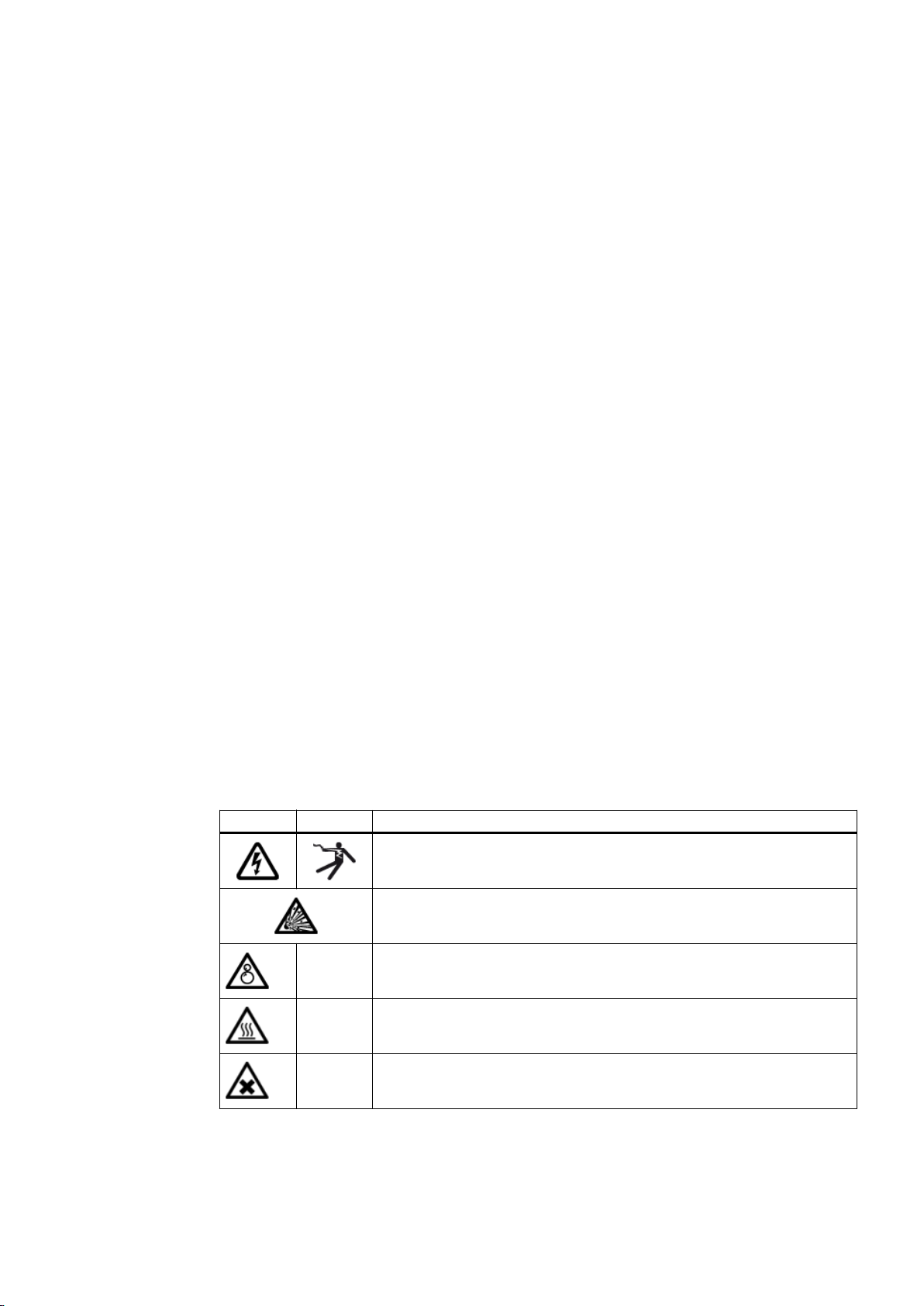
Table 2-1 General warnings........................................................................................................................11
Table 2-2 Temperature classes (TX) for explosive atmospheres as a result of gases, vapours or mists......16
Table 2-3 Maximum surface temperature (TX) for an explosive atmosphere as a result of dust/air
mixtures.......................................................................................................................................16
Table 4-1 Types of preservative agents for long-term storage....................................................................22
Table 5-1 Recommended assigned fits for bores with parallel key connection...........................................24
Table of contents
N-EUPEX / N-EUPEX DS 3100en
6Operating Instructions 10/2017

Table 5-2 Position of the parallel keyway....................................................................................................25
Table 5-3 Diameter and axial position of the tapped hole, tightening torque..............................................27
Table 5-4 Position of the tapped hole with respect to the parallel keyway..................................................28
Table 7-1 Table of faults..............................................................................................................................38
Table 8-1 Maintenance intervals.................................................................................................................43
Table 8-2 Maximum permissible torsional backlash for the types A and B (sizes 58 to 250)......................44
Table 8-3 Maximum permissible torsional backlash for the types A and B (sizes 280 to 710)....................44
Table 8-4 Maximum permissible torsional backlash for the types ADS and BDS (sizes 66 to 218)............44
Table 8-5 Maximum permissible torsional backlash for the types ADS and BDS (sizes 245 to 556)..........45
Table 11-1 Spare parts list for types A and ADS...........................................................................................54
Table 11-2 Spare parts list for types B and BDS...........................................................................................55
Table A-1 Speeds, geometry data and weights of type A............................................................................57
Table A-2 Speeds, geometry data and weights of type B............................................................................59
Table A-3 Speeds, geometry data and weights of type ADS.......................................................................60
Table A-4 Speeds, geometry data and weights of type BDS.......................................................................61
Table A-5 Maximum permissible shaft misalignment values during operation............................................62
Table A-6 Tightening torques for part 13 of types A and ADS.....................................................................63
Table A-7 Tightening procedure..................................................................................................................64
Table A-8 N‑EUPEX flexible elements.........................................................................................................65
Table A-9 N‑EUPEX DS flexible elements...................................................................................................66
Figures
Figure 3-1 Type A and ADS..........................................................................................................................19
Figure 3-2 Type B and BDS..........................................................................................................................20
Figure 4-1 Transport symbols.......................................................................................................................21
Figure 5-1 Tolerances for finished bore........................................................................................................25
Figure 5-2 Diameter and axial position of the tapped hole in the hub..........................................................26
Figure 5-3 Position of the balancing bore for single-plane balancing...........................................................29
Figure 5-4 Position of the balancing bore for two-plane balancing...............................................................29
Figure 5-5 Possible misalignment.................................................................................................................32
Figure 8-1 Markings for calculating the torsional backlash...........................................................................44
Figure 8-2 Tapped jacking hole for loosening coupling part 3 (3).................................................................45
Figure 11-1 Spare parts drawing for types A and ADS...................................................................................54
Figure 11-2 Spare parts drawing for types B and BDS...................................................................................55
Figure A-1 Type A.........................................................................................................................................57
Figure A-2 Type B.........................................................................................................................................59
Figure A-3 Type ADS....................................................................................................................................60
Figure A-4 Type BDS....................................................................................................................................61
Table of contents
N-EUPEX / N-EUPEX DS 3100en
Operating Instructions 10/2017 7

Table of contents
N-EUPEX / N-EUPEX DS 3100en
8Operating Instructions 10/2017

Introduction 1
1.1 About these instructions
These instructions describe the coupling and provide information about its handling - from
assembly to maintenance. Please keep these instructions for later use.
Please read these instructions prior to handling the coupling and follow the information in them.
1.2 Text attributes
The warning notice system is explained on the back of the inner cover. Always follow the safety
information and notices in these instructions.
In addition to the warning notices, which have to be observed without fail, you will find the
following text attributes in these instructions:
1. Procedural instructions are shown as a numbered list. Always perform the steps in the order
given.
● Lists are formatted as bulleted lists.
– The dash is used for lists at the second level.
(1) Numbers in brackets are part numbers.
Note
A note is an important item of information about the product, the handling of the product or the
relevant section of the instructions. The note provides you with help or further suggestions/
ideas.
1.3 Copyright
The copyright for these instructions is held by Flender.
These instructions must not be used wholly or in parts without our authorisation or be given to
third parties.
If you have any technical queries, please contact our factory or one of our service outlets (refer
to Service and support (Page 49)).
N-EUPEX / N-EUPEX DS 3100en
Operating Instructions 10/2017 9

Introduction
1.3 Copyright
N-EUPEX / N-EUPEX DS 3100en
10 Operating Instructions 10/2017

Safety instructions 2
2.1 General information
Instructions
These instructions are part of the delivery. Always keep these instructions close to the coupling.
Please make sure that every person who is commissioned to work on the coupling has read
and understood these instructions prior to handling the coupling and observes all of the points.
Only the knowledge of these instructions can avoid faults on the coupling and ensure fault-free
and safe operation. Non-adherence to the instructions can cause product or property damage
or personal injury. Flender does not accept any liability for damage or operating failures that
are due to non-adherence to these instructions.
State of the art
The coupling described here has been designed in consideration of the latest findings for
demanding technical requirements. This coupling is state-of-the-art at the time of printing these
instructions.
In the interest of further development, Flender reserves the right to make such changes to the
individual components and accessories that increase performance and safety whilst
maintaining the essential features.
Symbols
Table 2-1 General warnings
ISO ANSI Warning
Warning - hazardous electrical voltage
Warning - explosive substances
--- Warning - entanglement hazard
--- Warning - hot surfaces
--- Warning - substances that are harmful to health or are irritants
N-EUPEX / N-EUPEX DS 3100en
Operating Instructions 10/2017 11

ISO ANSI Warning
--- Warning - corrosive substances
--- Warning - suspended load
--- Warning - hand injuries
ATEX certification
Explanation regarding Machinery Directive 2006/42/EC
The couplings described here are “components” in accordance with the Machinery Directive
and do not require a declaration of incorporation.
ATEX Directive
The term "ATEX Directive" used in these instructions stands for the harmonisation legislation
of the European Union in compliance with the declaration of conformance for equipment and
protective systems for correct use in hazardous zones.
Protective clothing
In addition to the generally prescribed personal protective equipment (safety shoes, overalls,
helmet, etc.), also wear suitable safety gloves and safety goggles when handling the coupling.
Using the coupling
The relevant work safety and environmental protection regulations must be complied with at
all times during transport, assembly, installation, dismantling, operation and maintenance of
the coupling.
Only qualified personnel may operate, assemble, maintain and repair the coupling. Information
about qualified personnel can be found in the legal notes at the beginning of these instructions.
If lifting gear or load suspension devices are used for transporting, these have to be suitable
for the weight of the coupling.
If the coupling has visible damage, it may not be assembled or put into operation.
The coupling may only be operated in a suitable housing or with touch protection according to
applicable standards. This also applies to test runs and rotational direction checks.
Work on the coupling
Only carry out work on the coupling when it is not in operation and is not under load.
Safety instructions
2.1 General information
N-EUPEX / N-EUPEX DS 3100en
12 Operating Instructions 10/2017

Secure the drive unit against being switched on accidentally. Attach a notice to the switch
stating clearly that work is being carried out on the coupling. Ensure that the entire unit is not
under load.
2.2 Intended use
Only use the coupling according to the conditions specified in the service and delivery contract
and the technical data in the annex. Deviating operating conditions are considered improper
use. The user or owner of the machine or plant is solely liable for any resulting damage.
When using the coupling please specifically observe the following:
● Do not make any modifications to the coupling that go beyond the permissible machining
described in these instructions. This also applies to touch protection facilities.
● Only use original spare parts from Flender. Flender only accepts liability for original spare
parts from Flender.
Other spare parts are not tested and approved by Flender. Non-approved spare parts may
possibly change the design characteristics of the coupling and thus impact active and/or
passive safety.
Flender will accept no liability or warranty whatsoever for damage occurring as a result of
the use of non-approved spare parts. The same applies to any accessories that were not
supplied by Flender.
If you have any queries, please contact our customer service (see Service and support
(Page 49)).
2.3 Safety instructions for a coupling for use in potentially explosive
atmospheres
2.3.1 Marking
You can find a description of the coupling parts in chapter Description (Page 19).
A coupling designed in accordance with the ATEX Directive has a marking on the coupling
parts.
Coupling part 1 without electrically insulating flexible elements
One of the following markings is visible on the outer diameter of coupling part 1:
Version 1:
Flender GmbH II 2GD c IIC TX
46393 Bocholt - Germany I M2 c X
FLENDER couplings N‑EUPEX <Year of man‐
ufacture>
Safety instructions
2.2 Intended use
N-EUPEX / N-EUPEX DS 3100en
Operating Instructions 10/2017 13

Version 2:
Flender GmbH II 2G c IIC T4/T5/T6
-30 °C ≤ Ta ≤ +80 °C/+70 °C/+55 °C
46393 Bocholt - Germany II 2D c T 110 °C -30 °C ≤ Ta ≤ +80 °C
FLENDER couplings N‑EUPEX <Year of man‐
ufacture>
I M2 c -30 °C ≤ Ta ≤ +80 °C
Coupling part 1 with flexible elements for low-temperature use
One of the following markings is visible on the outer diameter of coupling part 1:
Version 1:
Flender GmbH II 2GD c IIC TX
46393 Bocholt - Germany I M2 c X
FLENDER couplings N‑EUPEX <Year of man‐
ufacture>
Version 2:
Flender GmbH II 2G c IIC T6 -50 °C ≤ Ta ≤ +50 °C
46393 Bocholt - Germany II 2D c T 80 °C -50 °C ≤ Ta ≤ +50 °C
FLENDER couplings N‑EUPEX <Year of man‐
ufacture>
I M2 c -50 °C ≤ Ta ≤ +50 °C
Coupling part 1 with electrically insulating flexible elements
One of the following markings is visible on the outer diameter of coupling part 1:
Version 1:
Flender GmbH II 2GD c IIB TX
46393 Bocholt - Germany I M2 c X
FLENDER couplings N‑EUPEX <Year of man‐
ufacture>
Version 2:
Flender GmbH II 2G c IIB T4/T5/T6
-30 °C ≤ Ta ≤ +80 °C/+70 °C/+55 °C
46393 Bocholt - Germany II 2D c T 110 °C -30 °C ≤ Ta ≤ +80 °C
FLENDER couplings N‑EUPEX <Year of man‐
ufacture>
I M2 c -30 °C ≤ Ta ≤ +80 °C
Safety instructions
2.3 Safety instructions for a coupling for use in potentially explosive atmospheres
N-EUPEX / N-EUPEX DS 3100en
14 Operating Instructions 10/2017

Coupling part 2 or 4
Coupling part 2 or coupling part 4 is stamped with .
Undrilled or predrilled coupling
A coupling part with Ex marking, the letter "U" and the Flender order number has been delivered
undrilled or predrilled.
Note
Undrilled or predrilled coupling with Ex marking
Flender only supplies an undrilled or predrilled coupling with Ex marking on the condition that
the customer assumes the responsibility and liability for correct finishing work in a declaration
of exemption.
2.3.2 Conditions of use
Note
Note also the material-dependent permissible ambient temperature of the flexible elements
(12) in accordance with sections N-EUPEX flexible elements (12) (Page 65) and N-EUPEX
DS flexible elements (12) (Page 66).
A coupling designed in accordance with the ATEX Directive is suitable for the following
conditions of use:
● Equipment group I
– Category M2
● Equipment group II
– Category 2 and 3
– Group of substances G, zone 1 and 2
– Group of substances D, zone 21 and 22
– Explosion group IIA, IIB and IIC
– Explosion group IIA and IIB when electrically insulating flexible elements are used
Conditions of use for products with TX marking
The maximum ambient temperature stated in the following tables applies to the temperature
in the direct vicinity of the coupling and the temperature of adjacent components.
Safety instructions
2.3 Safety instructions for a coupling for use in potentially explosive atmospheres
N-EUPEX / N-EUPEX DS 3100en
Operating Instructions 10/2017 15

1. Gases, vapours or mists
Check the ambient temperature for use of the coupling in the relevant temperature class.
Table 2-2 Temperature classes (TX) for explosive atmospheres as a result of gases, vapours or mists
Max. ambient temperature Temperature class
80 °C T4
70 °C T5
55 °C T6
2. Dust/air mixtures
Check the ambient temperature.
Table 2-3 Maximum surface temperature (TX) for an explosive atmosphere as a result of dust/air
mixtures
Max. ambient temperature Max. surface temperature
80 °C 110 °C
Notes concerning operation of the coupling in potentially explosive atmospheres
● Only use the coupling underground in mines in potentially explosive atmospheres together
with drive motors that can be switched off in the event of the formation of an explosive
atmosphere.
● Earth machines that are connected via the coupling with a leakage resistance of less than
106 Ω.
● If you want to use a coated coupling in potentially explosive atmospheres, please note the
requirements concerning the conductivity of the paint and the limitation on the paint layer
thickness applied in accordance with EN 13463-1. No build-up of electrostatic charges is
to be expected with a paint layer thickness of less than 200 μm.
2.4 General warning notices
DANGER
Danger due to bursting of the coupling
The coupling may burst if it is not used properly. There is a risk of fatal injury from flying
fragments. Bursting of the coupling can lead to an explosion in potentially explosive
atmospheres.
● Use the coupling for the purpose for which it is intended.
Safety instructions
2.4 General warning notices
N-EUPEX / N-EUPEX DS 3100en
16 Operating Instructions 10/2017

DANGER
Risk of explosion when using coupling parts without Ex marking
Coupling parts without Ex marking have not been approved for use in potentially explosive
atmospheres. These coupling parts can lead to an explosion during operation.
● Only use couplings with Ex marking in potentially explosive atmospheres.
DANGER
Danger
Risk of injury due to the use of unsuitable and/or damaged components. The use of unsuitable
and/or damaged components can lead to an explosion in potentially explosive atmospheres.
● Observe the information regarding conditions of use.
DANGER
Danger of explosion
Improper operation of the coupling can lead to an explosion in potentially explosive
atmospheres.
● Please observe the notes concerning operation of the coupling in potentially explosive
atmospheres.
DANGER
Danger from hot coupling parts
Risk of injury due to hot surfaces. Hot coupling parts can lead to an explosion in potentially
explosive atmospheres.
● Wear suitable protective equipment (gloves, safety goggles).
● Ensure that the area is not at risk of explosion.
WARNING
Risk of chemical burns due to chemical substances
There is a risk of chemical burns when handling aggressive cleaning agents.
● Please observe the manufacturer's information on how to handle cleaning agents and
solvents.
● Wear suitable protective equipment (gloves, safety goggles).
CAUTION
Physical injury
Risk of injury due to falling coupling parts.
● Secure the coupling parts to prevent them from falling.
Safety instructions
2.4 General warning notices
N-EUPEX / N-EUPEX DS 3100en
Operating Instructions 10/2017 17

Safety instructions
2.4 General warning notices
N-EUPEX / N-EUPEX DS 3100en
18 Operating Instructions 10/2017

Description 3
The N‑EUPEX or N‑EUPEX DS couplings described here are torsionally flexible, damping pin
couplings and are available in various types and sizes. The couplings can be used in
accordance with the ATEX Directive in potentially explosive atmospheres if they have a CE
marking.
Types A and B are fail-safe. Types ADS and BDS have no fail-safe device.
These instructions describe the assembly and operation of an N‑EUPEX or N‑EUPEX DS
coupling arranged horizontally with a shaft-hub connection made by a cylindrical or conical
bore with parallel key. Please consult Flender if you want to use a different type of installation.
Application
N‑EUPEX couplings are designed for use in all kinds of machines.
N‑EUPEX DS couplings are used for applications which require the input and output to be
disconnected from one another in the event of destruction of the flexible elements.
Design
The diagrams show the various types with their constituent parts and their part numbers.
1 Coupling part 1
2 Coupling part 2
3 Coupling part 3
12 Flexible element
13 Cylinder-head screw
16 Cylindrical pin
only with type A sizes 560 to 710
Figure 3-1 Type A and ADS
N-EUPEX / N-EUPEX DS 3100en
Operating Instructions 10/2017 19

1 Coupling part 1
4 Coupling part 4
12 Flexible element
Figure 3-2 Type B and BDS
Description
N-EUPEX / N-EUPEX DS 3100en
20 Operating Instructions 10/2017
Other manuals for N-EUPEX
1
This manual suits for next models
1
Table of contents
Popular Adapter manuals by other brands

TRENDnet
TRENDnet TEW-623PI Quick installation guide

Bosch
Bosch Flasher LT user manual

ZyXEL Communications
ZyXEL Communications Wireless LAN USB Adapter ZyAIR 200 user guide

cable matters
cable matters 201046 user manual

iDataLink
iDataLink maestro Rr install guide

IOGear
IOGear UpStream GUV302P quick start guide