Flex Fitness KH-706J2 User manual

1
USER’S MANUAL
Elliptical bike
KH-706J2

2
Safety Instructions
•
To ensure the best safety of the exerciser, regularly
check it on damages and worn parts.
• If you pass on this exerciser to another person or if
you allow another person to use it, make sure that
that person is familiar with the content and
instructions in these instructions.
• Only one person should use the exerciser at a time.
• Before the first use and regularly make sure that all
screws, bolts and other joints are properly tightened
and firmly seated.
• Before you start your work-out, remove all
sharp-edged objects around the exerciser.
• Only use the exercise for your work-out if it works
flawlessly.
• Any broken, worn or defective part must immediately
be replaced and/or the exerciser must no longer be
used until it has been properly maintained and
repaired.
• Parents and other supervisory persons should be
aware of their responsibility, due to situations which
may arise for which the exerciser has not been
designed and which may occur due to children’s
natural play instinct and interest in experimenting.
• If you do allow children to use this exerciser, be sure
to take into consideration and assess their mental
and physical condition and development, and above
all their temperament. Children should use the
exerciser only under adult supervision and be
instructed on the correct and proper use of the
exerciser. The exerciser is not a toy.
• Make sure there is sufficient free space around the
exerciser when you set it up.
• To avoid possible accidents, do not allow children to
approach the exerciser without supervision, since
they may use it in a way for which it is not intended
due to their natural play instinct and interest in
experimenting.
• Please note that an improper and excessive
work-out may be harmful to your health.
• Please note that levers amd other adjustment
mechanisms are not projecting into the area of
movement during the work-out.
•When setting up the exerciser, please make sure
that the exerciser is standing in a stable way and
that any possible unevenness of the floor is
evened out.
•Always wear appropriate clothing and shoes which
are suitable for your work-out on the exerciser.
The clothes must be designed in a way so that
they will not get caught in any part of the exerciser
during the work-out due to their form (for example,
length). Be sure to wear appropriate shoes which
are suitable for the work-out, firmly support the
feet and which are provided with a non-slip sole.
•Be sure to consult a physician before you start any
exercise program. He may give you proper hints
and advice with respect to the individual intensity
of stress for you as well as to your work-out and
sensible eating habits.

3
• Assemble the exerciser as per assembly instructions
and be sure to only use the strucutral parts provided
with the exerciser and designed for it. Prior to the
assembly, make sure the contents of the delivery is
complete by referring to the parts list of the
assembly and operating instructions.
• Be sure to set up the exerciser in a dry and even place and
always protect it from humidity. If you wish to protect the place
particularly against pressure points, contamination, etc.,
it is recommended to put a suitable, non-slip mat under the exercise
• The general rule is that exercisers and training devices are no
toys. Therefore, they must only be used by properly informed
or instructed persons.
•
Stop your work-out immediately in case of dizziness,
nausea, chest pain or any other physical symptoms. In
case of doubt, consult your physician immediately.
•Children, disabled and hadicapped persons should
use the exercise only under supervision and in
presence of another person who may give support and
useful instructions.
•Be sure that your body parts and those of other
persons are never close to any moving parts of the
exerciser during its use.
•When adjusting the adjustable parts, make sure they
are adjusted properly and note the marked, maximum
adjusting position, for example of the saddle support,
respectively.
•Do not work out immediately after meals!

4
Exploded drawing
E-1
P-1
M-1
J-1
N-1
Q-1
E-4
E-3
B-5
B-3
B-2
A-1
B-1
B-4
S
C-2
C-1
E-2
F-1
K-3
D-1
K-2
K-1
K-9
K-8
H-1
I-1
R
N-5
K-4
K-5
K-6
K-7
N-6
M-2
M-3
M-4
M-5 M-6
M-7
M-8 M-9
H-2
N-7
N-8
P-2
P-3
P-4
P-5
P-6
P-7
P-8
P-9
P-10
N-15
N-9
N-2
N-3
N-4
G-1
Q-2
Q-4
Q-3
D-2
D-4 D-3 D-7 D-5 D-6 D-8
L-10
L-11
I-2
I-3
I-4
J-2
J-3 J-4
D-10
T-2 T-3 T-4 T-5
T-6
F-2
F-3
F-4
C-3
G-2
O
A-2
J-5
D-9
B-6
T-7 T-8
N-3
N-4
N-5
N-3
N-4
N-11
N-12
N-3
N-13
N-10
Q-5
D-10
P-14
J-6
L-1
L-2
L-6 L-4
L-5
L-10
L-7 L-8
L-9
L-3
I-1
I-2
I-4
T-1
N-16
N-17
N-11

5
Part List
part no. description specification q'ty
A Computer set 1
A-1 Computer SM-3720-71 1
A-2 Bolt M5*0.8*10L 4
B Fixing bar set 1
B-1 Fixed handlebar 1
B-2 Foam D23x4Tx450L 2
B-3 Half ball cap D25.4*31L 2
B-4 Handle pulse cable 600L 2
B-5 Handle pulse sensor PE18 2
B-6 Screw ST4x1.41x20L 2
C Handlebar post set 1
C-1 Handlebar post 1
C-2 Bushing D19.15x(D25.6x32)xL(17+3) 2
C-3 Upper computer cable 900L 1
D Main frame set 1
D-1 Main frame 1
D-2 Inner tube D56*97 1
D-3 Motor 1
D-4 Screw ST4.2*1.4*15L 2
D-5 Sensor cable 100L 1
D-6 Bolt M5*0.8*12L 1
D-7 Lower computer cable 1300L 1
D-8 Tension cable D1.2*230L 1
D-9 Bearing #6003ZZ 2
D-10 Electric cable 450L 1
E Handlebar set 1
E-1 Right handle bar D31.8*560*1.5T 1
E-2 Left handle bar D31.8*560*1.5T 1
E-3 Mushroom cap D1 1/4"*45 L 2
E-4 Foam D30*4T*440L 2
F Front stabilizer set 1
F-1 Front stabilizer D60x500Lx1.5T 1

6
F-2 Round foot cap D60xD67x43 2
F-3 Foot cap D60x54.5L 2
F-4 Screw ST4*1.41*12L 4
G Rear stabilizer set 1
G-1 Rear stabilizer D60x1.5Tx480L 1
G-2 Foot cap(12 angle) D60xD75x50L 2
H Pedal set 395*120*70 1set
H-1 Left pedal 395*120*70 1
H-2 Right pedal 395*120*70 1
I Crank set 1
I-1 Crank 2
I-2 Anti-loosen nut M10*1.25*10T 2
I-3 Side cap D36x14 2
I-4 Round cover D346*25 2
J Chain cover set 1
J-1 Upper decorative cover 530*85 1
J-2 Round ring for chain cover D81*D62*9T 1
J-3 Left chain cover 800*75*520 1
J-4 Right chain cover 800*75*520 1
J-5 Screw ST4.2x1.4x20L 9
J-6 cross screw ST4.2*20L 2
K Fixing plate for magnet set 1
K-1 Fixing plate for magnet 1
K-2 Spring D1.0*55L 1
K-3 Nylon nut M6*1*6T 1
K-4 Flat washer D13*D6.5*1.0T 1
K-5 Nylon washer D6*D19*1.5T 1
K-6 Nut M6*1*6T 1
K-7 Bolt M6*65L 1
K-8 Nylon nut M8*1.25*8T 1
K-9 Bolt M8*52L 1
K-10 Magnet 39.5*10*25 8
K-11 Plate for magnet 40*3*3 7
L Fixing plate for idle wheel set 1

7
L-1 Fixing plate for idle wheel 1
L-2 Spring D3*D17*59L 1
L-3 Plastic flat washer D10*D24*0.4T 1
L-4 Flat washer D50*D10*3.0T 1
L-5 Bolt M8*1.25*30L 1
L-6 Flat washer D30*D8.2*3.0T 1
L-7 Nylon nut M10*1.5*10T 1
L-8 Idle wheel D42xD38x24 1
L-9 nut M8*1.25*6T 1
L-10 nylon nut M8*1.25*8T 1
M Belt wheel set 1
M-1 Waved washer D17*D22*0.3T 2
M-2 Flat washer D23*D17.2*1.5T 1
M-3 C-clip S-17(1T) 2
M-4 Belt 1118L PJ5 1
M-5 Belt wheel D280*19 1
M-6 Crank axle 1
M-7 Round magnet M02,1
M-8 Bolt M6*1.0*15L 4
M-9 Nylon nut M6x1.0x6T 4
N-1 Square neck bolt M8x1.25x75L 4
N-2 Domed nut M8x1.25x15L 4
N-3 Spring washer D15.4xD8.2x2T 18
N-4 Curved washer D22xD8.5x1.5T 14
N-5 Allen bolt M8x1.25x20L 12
N-6 Coned washer D14*D8*4 2
N-7 Club knob D40*M6*12 4
N-8 Flat washer D14xD6.5x0.8T 4
N-9 Square neck bolt M6*1*45L 4
N-10 Waved washer D26*D19.5*0.3T 2
N-11 Screw cover D29*21(M8) 2
N-12 Bolt M8x1.25x25 2
N-13 Flat washer D25xD8.5x2T 2

8
N-14 Screw cover D28*17(M10) 2
N-15 Screw cover D30*17(M12) 2
N-16 pedal axle cover D30*11L 2
N-17 round screw M8*1.25*16L 2
O Protective cover 114*76*43 1
P Pedal assemble set 1
P-1 Pedal welding tube 2
P-2 Square cap 30*60*15 4
P-3 Nylon nut M10*1.5*10T 2
P-4 Flat washer D20*D11*2.0T 2
P-5 Bushing D19.15x(D25.6x32)xL(17+3) 4
P-6 Bushing D29*D11.9*9T 4
P-7 C-clip D21.5xD17.5x1.2T 4
P-8 Joint 2
P-9 Flat washer D24*D13.5*2.5T 2
P-10 Ladder bolt M10*1.5*58L 2
P-11 pedal axle D19*128.5L 2
Q-1 Moveable supporting tube 2
Q-2 Bushing D19.15x(D25.6x32)xL(17+3) 8
Q-3 Front pedal axle D19x72L 2
Q-4 C-clip D21.5xD17.5x1.2T 4
Q-5 Waved washer D26*D19.5*0.3T 2
R Adaptor 240V 50HZ 1
S Axle D19x334.5(M8x1.25) 1
T Fly wheel set 1
T-1 Fly wheel D260x77L 1
T-2 Fly wheel axle D10x120L(3/8"-26UNF) 1
T-3 Fixing ring D13*D10*1.9T 1
T-4 Nut D9.5x4T(3/8"-26UNFx4T) 1
T-5 Anti-loosen nut 3/8"-26UNF*6.5T 2
T-6 Nut D9.5x5T(3/8"-26UNFx5T) 2
T-7 Bearing #6000ZZ 2

9
CHECK LIST (CONTENTS OF PACKAGE)
DC
E
H
F
G
A
B
R
S
O
X1
X1
X1
X1
X1
X1
X1
X1
X1
X1
X1
M8*1.25*15L 4PCS
N-2
M6x1x45L 4PCS
N-9
D40xM6x12 4PCS
N-7
D14xD6.5x0.8T 4PCS
N-8
(MM)
Step-1
M8*1.25*75L 4PCS
N-1
D15.4xD8.2x2T 4PCS
N-3
D22xD8.5x1.5T 4PCS
N-4
M8x1.25X20L 6PCS
N-5
D22xD8.5x1.5T 4PCS
N-4 D22xD8.5x1.5T 4PCS
N-4
D15. 4xD8 .2x2T 6P CS
N-3
D
1
4
*
D
8
*
4
T
2PCS
N-6
D15.4xD8.2x2T 2PCS
N-3
N-10
D
2
6
*
D
1
9
.
5
*
0
.
3
T
2PCS
D
2
5
*
D
8
.
5
*
2
T
2PCS
N-13
M8*1 .25*25L 2 PCS
N-12
D15.4xD8.2x2T 6PCS
N-3
M8x1.25X20L 4PCS
N-5
D
2
9
*
2
1
(
M
8
)
2PCS
N-11
Step-4
Step-5
Step-3
D
2
8
*
1
7
(
M
1
0
)
2PCS
N-14 D
3
0
*
1
7
(
M
1
2
)
2PCS
N-15
M8
M8
M12M12M10M10
2PCS
1PCS
X1
N
M8x1.25X20L 2PCS
N-5
D22xD8.5x1.5T 2PCS
N-4
P&Q-1
Step-2
M8*1.25*16L 2PCS
N-17
D30*11L 2PCS
N-16
X1
10
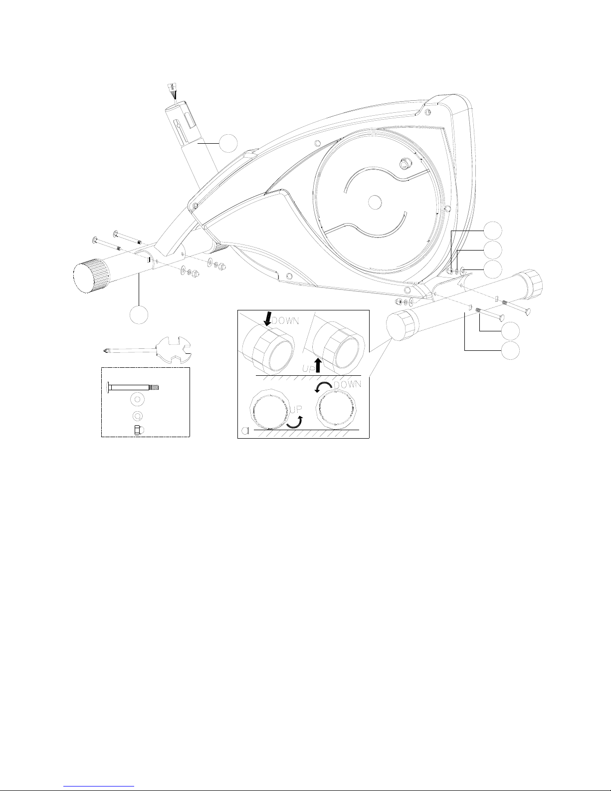
STEP 1
STEP-1
N-1x4
N-4x4
D
G
N-1
N-2
N-3
N-4
F
N-3x4
N-2x4
1) Assemble the front stabilizer (F) and rear stabilizer (G) onto the main frame (D) by
using the square neck bolt (N-1), the curved washer (N-4), the spring washer
(N-3), and the cup nut (N-2).
2) Adjust the proper height by turning the wheel of rear foot cap.
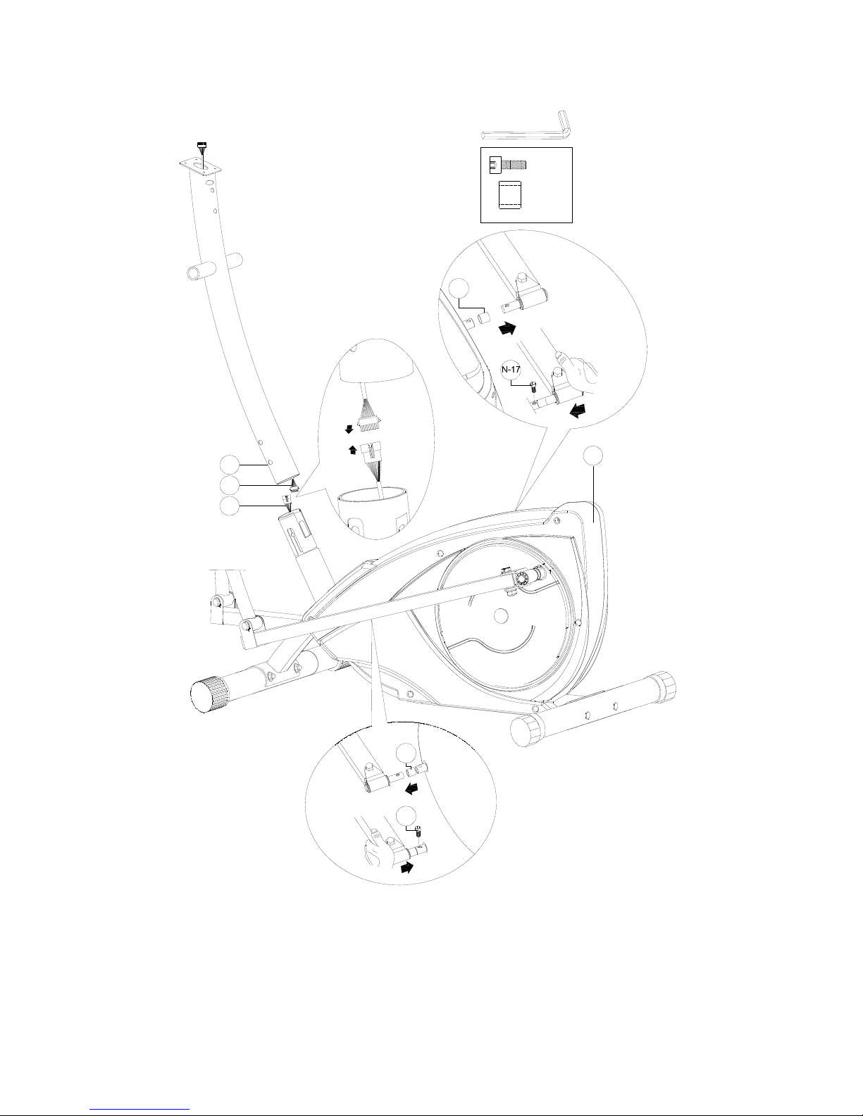
11
STEP 2
STEP-2
C
D-7
C-3
D
N-17
N-16
N-16
N-17x2
N-16x2
1) Connect the upper computer cable (C-3) to the lower computer (D-7), then insert
the handlebar post (C) on the main frame.
2) Assemble the pedal axle cover (N-16) on the pedal axle
3) Fix the pedal axle onto main frame using bolt (N-17)

12
STEP 3
STEP-3
CQ-1
S
N-11
N-12
N-3
N-13
N-10
N-10
N-12x2
E
N-4
N-3
N-5
N-3x2
N-13x2
N-10x2
N-4x4
N-5x4
N-10 C
N-10 Q-1 S
N-11
M8 N-11x2
N-3x4
N-11
1) Connect the movable handlebar support (E) to the handlebar support (Q-1) by
using the bolt (N-5), the flat washer (N-3) and the waved washer (N-4).
2) Joint the moving handlebar(E) with front post (C) through swing axle (S) by using
Waved washer (N-10),Bolt(N-3),flat washer (N-13), spring washer (N-3) and cap
the bolt cover (N-11)

13
STEP 4
STEP-4
B
N-4
N-3
N-5
O
N-5x2
N-3x2
N-4x2
1) Assemble the fixed handlebar (B) and the cover (O) on the handlebar post (C) by
using the curved washer (N-4), the spring washer (N-3) and the Allen bolt (N-5).
2) Through the upper computer cable and handpulse cable out from the handlebar
post
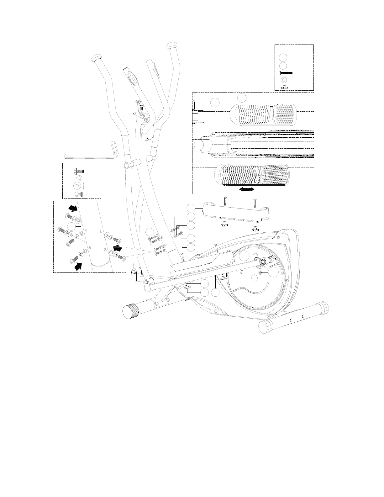
14
STEP 5
STEP-5
A
N-9X4
BN-5x6
(A)
(B)
N-6
N-3
N-4
N-7
N-8
N-9
H
P
H
P
N-5
N-15
N-14
N-8X4
N-7X4
N-3x6
N-4x4
N-6x2
M12
M10 N-14X2
N-15X2
N-6
1) Fix the pedal (H) onto the pedal support tube (P) by using bolt (N-9),
knob (N-7) and flat washer (N-8) (Fig A)
2) Cap the bolt cover (N-14) and (N-15)
3) Insert the handlebar post into the support of main frame by using bolt (N-5), spring
washer (N-3) and curved washer (N-4) and coned washer (N-6) (Fig B)

15
Step 6
A-2x4
STEP-6
A
C-3
B-4
B-4
A-2
R
A-1
C-3
1) Connect the upper computer cable (C-3) and the handle pulse cable (B-4) with the
computer (A-1), then fix the computer (A-1) on the handlebar post by using the
screws(A-2)
2) Connect the adaptor (R) to hole of frame on the rear of the bike.

16
SM3720 INSTRUCTION MANUAL
DISPLAY FUNCTIONS :
ITEM DESCRIPTION
TIME .Workout time displayed during exercise.
.Range 0:00 ~ 99:59
SPEED .Workout speed displayed during exercise.
.Range 0.0 ~ 99.9
DISTANCE .Workout distance displayed during exercise.
.Range 0.0 ~ 99.9
CALORIES .Burned calories during workout display.
.Range 0 ~ 999
PULSE .Pulse bpm displayed during exercise.
.Pulse alarm when over preset target pulse.
RPM .Rotation per minute
.Range 0 ~ 999
WATTS .Workout power consumption
.Range 0 ~ 350
MANUAL .Manual mode workout.
PROGRAM .12 PROGRAM selection.
USER .User creates resistance level profile.
H.R.C. .Target HR training mode.
WATT .Watt constant training mode.

17
KEYS :
OPERATION:
POWER ON
Plug in power supply, computer will power on and display all segments on LCD for 2 seconds. Enter into user
data setting mode (Age, Gender, Height, Weight)
After 4 minutes without pedaling or pulse input, console will enter into power saving mode.
Press any key may wake the console up.
Manual Mode
Press START in main menu may start workout in manual mode.
1. Press UP or DOWN to select workout program, choose Manual and press MODE to enter.
2. Press UP or DOWN to preset TIME.DISTANCE.CALORIES.PULSE and press MODE to confirm.
3. Press START/STOP keys to start workout. Press UP or DOWN to adjust load level.
4. Press START/STOP keys to pause workout. Press RESET to reverse to main menu.
ITEM DESCRIPTION
Up Increase resistance level
Down Decrease resistance level
Mode Confirm setting or selection.
Reset Hold on pressing for 2 seconds, computer will reboot and start from user setting.
Reverse to main menu during presetting workout value or stop mode.
Start/ Stop Start or Stop workout.
Recovery Test heart rate recovery status.
Body fat Test body fat% and BMI.

18
Program Mode
1. Press UP or DOWN to select workout program, choose Program and press MODE to enter.
2. Press UP or DOWN to preset workout TIME.
3. Press START/STOP keys to start workout. Press UP or DOWN to adjust load level.
Press START/STOP keys to pause workout. Press RESET to reverse to main menu.
User Program Mode
1. Press UP or DOWN to select workout program, choose User and press MODE to enter.
2. Press UP or DOWN to set load level of each column, and press MODE to next one. (Total column = 20)
3. Hold on pressing MODE to finish or quit setting.
4. Press UP or DOWN to preset workout TIME.
5. Press START/STOP button to start workout. Press UP or DOWN to adjust load level.
6. Press START/STOP button to pause workout. Press RESET to reverse to main menu.
H.R.C. mode
1. Press UP or DOWN to select workout program, choose H.R.C. and press MODE to enter.
2. Press UP or Down to select 55%.75%.90% or TAG (TARGET H.R.) (default: 100).
3. Press UP or DOWN to preset workout TIME.
4. Press START/STOP button to start or stop workout. Press RESET to reverse to main menu.
WATT Mode

19
1. Press UP or DOWN to select workout program, choose WATT and press MODE to enter.
2. Press UP or DOWN to preset WATT target. (default: 120)
3. Press UP or DOWN to preset TIME.
5. Press START/STOP button to start or stop workout. Press RESET to reverse to main menu.
Recovery
1. When pulse value display on the computer (hold handgrip or wear chest strap), press RECOVERY button.
2. TIME shows "0:60" (seconds) and count down.
Computer will show F1 to F6 after count down to 0 to test heart rate recovery status.
Body Fat Mode
1. When workout stop, press BODY FAT key.
2. Hold on handgrip, after 8 seconds, computer will show BMI, FAT% and fat symbol.
3. Press BODY FAT key again reverse to main menu.
<REFERENCE>
B.M.I. (Body mass index) integrated
B.M.I
SCALE
LOW LOW/MED MEDIUM MED/HIGH
RANGE <20 20-24 24.1-26.5 >26.5
BODY FAT:
SYMBOL — +▲◆
FAT%
SEX
LOW LOW/MED MEDIUM MED/HIGH
MALE <13% 13%-25.9% 26%-30% >30%
FEMALE <23% 23%-35.9% 36%-40% >40%
NOTE:
1. This computer require 6V, 500mA adaptor.
2. When user stop pedaling for 4 minutes, computer will enter into power save mode, all setting
and exercise data will stored until user start exercise again.
3. When computer act abnormal, please plug out the adaptor and plug in again.
Table of contents
Popular Elliptical Trainer manuals by other brands


Keys Fitness
Keys Fitness CardioMax CM708EL owner's manual

Precor
Precor Elliptical Fitness Crosstrainer EFX 5.25 Assembly guide

Precor
Precor Resolute RSL 714 Assembly guide

Sole Fitness
Sole Fitness E95s owner's manual

Mobiclinic
Mobiclinic ATLAS instruction manual

Spirit
Spirit XE395 Elliptical owner's manual