York International X730 User manual


SAFETY GUIDELINES:
Please read and follow the following safety guidelines:
Read this owner’s manual and follow the instructions.
YORK X730 CROSSTRAINER
The is designed for use and enjoyment in the home (NOT FOR COMMERCIAL USE). By following the
above precautions and using good judgement and common sense, you will have a safe and pleasurable exercise
regimen with the .
YORK X730
YORK X730
CAREAND MAINTENANCE
Use a warm damp cloth with mild detergent
to keep your clean.YORK X730
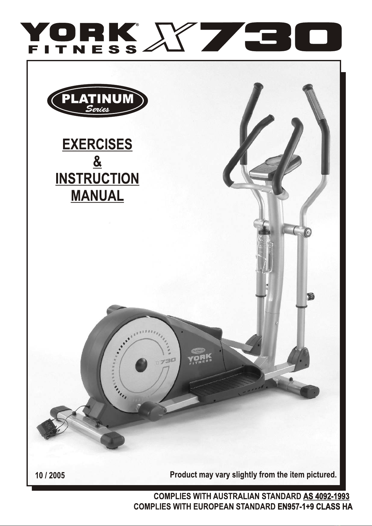
TOOLS REQUIRED
The tools enclosed in the carton are three allen keys
(one has a screwdriver function) and one multi-purpose spanner.
SHOULD YOU REQUIREANYASSISTANCE REGARDING THIS PRODUCT PLEASE CONTACT YORK DIRECTLY.
YORK X730 / 02
HELP LINE (8:30am- 16:30pm)
U.K. AUSTRALIA
YORK BARBELL (U.K.) LTD.
CHURCHILLWAY, DAVENTRY,
NORTHANTS, NN11 4YB ENGLAND
TEL: (01327) 701-824
FAX: (01327) 706-704
E-MAIL: [email protected]
HELP LINE (8:00am- 16:00pm)
YORK BARBELL (AUST.) PTY. LTD.
UNIT 1, LOT2, SWAFFHAM ROAD,
MINTO, N.S.W. 2566AUSTRALIA
TEL: (02) 9603-8444
FAX: (02) 9603-8555
E-MAIL: [email protected]
F I T N E S S
F I T N E S S
U.S.A.
YORK BARBELL USA.
3300 BOARD ROAD.
YORK, PA17402
TEL: +1-717-767-6481
FAX: +1-717-764-0416
E-MAIL: [email protected]
HELP LINE (8:00am- 17:00pm)
F I T N E S S
Keep hands away from moving parts.
The max. user weight of 136kgs ( 300lbs ) has been determined according to European Standards.
This product is not suitable for therapeutic purposes ( Class B & C ).
Wear proper workout clothing: Do not wear loose clothing.
Do not wear shoes with leather soles or high heels. Tie all long hair back.
Do not rock the unit from side to side.
Care should be taken when mounting and dismounting the unit.
Do not place any liquids on any part of the YORK X730.
Do not use any accessories that aren't specifically recommended by
the manufacturer, these might cause injuries or cause the unit to fail.
Always consult your doctor before undertaking any exercise programe.
Work within your recommended exercise level, do NOT work to exhaustion.
If you feel any pain or abnormal symptoms, STOPYOUR WORKOUT IMMEDIATELY.
Consult your physician immediately.
TAKE CARE TO PROTECT CARPETS AND FLOOR in case of leakages. This product is a machine
and contains moving parts which have been greased / lubricated and could leak.
TAKE CARE TO PROTECT CARPETS AND FLOOR
Assemble and operate the YORK X730 on a solid, level surface.
Keep the area behind the YORK X730 clear.
Always use your YORK X730 in adequate space e.g., at least 2 ft. (60cm) clearance on each side.
Never allow children on or near the YORK X730.
Always check the YORK X730 before using it, in particular make sure all parts
are assembled, and nuts and bolts are tightened.
Do not use the YORK X730 if the unit is disassembled in any way.
WARNING: Injuries could occur particularly to young children if the guards are removed and
not correctly reinstated.
WE DO NOT RECOMMEND THE REMOVAL OF THE GUARDS.
Always check the guards to ensure they are secured before use.
If guards are not secured tighten the screws of the guards.
The safety level of the equipment can be maintained only if it is regularly examined for damage and
wear e.g. ropes, pulleys & connection points.
Replace defective components immediately and/or keep the equipment out of use until repair.
Component such as pulleys, bearings and cables are always more susceptible to wear. Special
attention should be taken to inspect these component before use.
WARNING: Injuries to health may result from incorrect use of this equipment. Always correctly
follow the instructions that are set out in this manual.
That adjustment devices are not left projecting as they may interfere with people.
This machine requires a 230V 50Hz / 6V 1000mAA.C.Adaptor. Use of adaptors not specifically
recommended by YORK may damage your machine and void your warranty.
230V 50Hz / 6V 1000mA

SHOULD YOU REQUIREANYASSISTANCE REGARDING THIS PRODUCT PLEASE CONTACT YORK DIRECTLY.
**
ASSEMBLY INSTRUCTIONS
GENERAL
WE RECOMMEND YOU HAVE SOMEONE ASSIST YOU IN LIFTINGAND ASSEMBLING
YOUR YORK X730 .
REMOVEALL THE PARTS OF YOUR FROM THE CARTONAND PLACE
THEM ON THE FLOOR CAREFULLY.
FOLLOW THESE INSTRUCTIONS CAREFULLYAND IT WILL MAKE IT EASIER FOR
YOU TOASSEMBLE YOUR
CROSSTRAINER YORK X730
YORK X730 CROSSTRAINER.
YORK X730 / 03
1. ATTACH THE REAR STABILIZER
The front stabilizer has moving wheels near each end.
Fix the front stabilizer to the main frame and
secure, using two carriage bolts, washers,
spring washers and nylon locknuts.
X4
A
A
NOTE: MAKE SURE you fasten the nuts and bolts
securely for your safety and comfort when
pedalling.
NOTE: MAKE SURE
ATTACH THE FRONT STABILIZER
REAR
STABILIZER
END CAP
2.
#5575-09
#5575-10 #5575-11 #5575-12
FRONT
STABILIZER
MOVING
WHEEL
Fix the rear stabilizer to the main frame and
secure, using two carriage bolts, spring washers,
washers and nylon locknuts.
Fix the plastic caps onto the locknuts once secured.
X4
#5575-57
NOTE: This equipment has been supplied
with some Nylon
Locknuts.
It is essential that the nuts are fully
tightened onto the bolts, so that
the bolt penetrates through the
nylon insert.
Fix the plastic caps onto the locknuts once secured.
The rear stabilizer has end caps with an adjustable
knob fitted under neath that can vary in height to
enable you to level the trainer on uneven floors.

3. ATTACH THE PEDALS TO THE POSTS
Rotate both pedal post assemblies backwards
so that the pedal posts are resting on the floor
as shown.
Attach the right pedal to the right pedal post and
secure, using two carriage bolts, washers,
spring washers and fixing knobs.
Attach the left pedal to the left pedal post and
secure, using two carriage bolts, washers,
spring washers & fixing knobs.
NOTE: There are three adjustable holes on the
pedal post for you to adjust the pedal to a
suitable position.
MAKE SURE you fix both pedals into the
same positions on the pedal posts.
NOTE:
MAKE SURE
B
A
NOTE: The curved edge of each pedal must
be fixed onto the pedal post facing
outwards.
NOTE:
X2
X2
CURVED
EDGE
OF PEDAL
THIS SIDE
#5575-25
#5575-27
#5575-26
#5575-28
#5575-25
#5575-27
#5575-26
#5575-28
X2
X2
RIGHT
PEDAL
POST
RIGHT
PEDAL
LEFT
PEDAL
LEFT
PEDAL
POST
BRACKET
POINTING
DOWN
SHOULD YOU REQUIREANYASSISTANCE REGARDING THIS PRODUCT PLEASE CONTACT YORK DIRECTLY.
**
YORK / 04X730

SHOULD YOU REQUIREANYASSISTANCE REGARDING THIS PRODUCT PLEASE CONTACT YORK DIRECTLY.
**
YORKX730 / 05
4. ATTACH THE FRONT POST
Rest the front post on the front post
mounting tube carefully as shown.
Connect the sensor wire plug on the main
frame to the middle wire socket protruding
at the end of the front post.
Check the middle wire runs up the front
post and out of the top - later this will
to the computer.connect
NOTE: TAKE CARE to ensure the wire is
connected as tightly as possible.
ASENSOR
WIRE
MIDDLE
WIRE
FRONT
POST
B
C
Insert the front post into the front post
mounting tube and secure, using four allen
head bolts, spring washers and washers.
X4
Fix the central handle bar to the front post
via the fixing bracket using two allen head
bolts, spring washers and washers.
NOTE: TAKE CARE to ensure that the hand
pulse sensor cables do not get trapped
when you attach the centre bar.
NOTE: TAKE CARE
X2
#5575-19 #5575-11 #5575-10
#5575-50 #5575-11 #5575-10
CENTRAL
HANDLE BAR
FIXING
BRACKET
NOTE: TAKE CARE to ensure that the wire
does not get trapped when you attach
the front post.
NOTE: TAKE CARE
MAKE SURE you fasten the bolts
securely for your safety and comfort
when pedalling.
MAKE SURE
HAND
PULSE
SENSOR
CABLES
FRONT
POST

SHOULD YOU REQUIREANYASSISTANCE REGARDING THIS PRODUCT PLEASE CONTACT YORK DIRECTLY.
**
YORK X730 / 06
5.
A
B
C
D
E
ATTACH THE HANDLE BAR POSTS
Insert the handle bar pivot rod through the pivot rod
bushes fitted on the handle bar bracket carefully as shown.
NOTE: TAKE CARE to ensure that the middle wire does not
get trapped when you insert the pivot rod.
NOTE: TAKE CARE
Attach the right handle bar onto the handle bar pivot rod
carefully. Connect the hand pulse sensor wire socket,
which protrudes from the pivot rod bush on handle bar, to
the middle wire plug protruding from the end of the handle
bar bracket securely.
NOTE: TAKE CARE to ensure wires do not get trapped
when fitting handlebar
NOTE: TAKE CARE
X1
#5575-19 #5575-11 #5575-42
Slide the right low handle bar post into the right handle
bar post and secure in position with the adjusting knob.
#5575-43
X1
Slide the rest of the wires into the bush on the handle bar
bracket carefully.
NOTE: TAKE CARE to ensure wires do not get trapped
when fitting handlebar
NOTE: TAKE CARE
Secure the right handle bar post to the handle bar bracket
by using one allen head bolt, spring washer and washer.
F
HANDLE
BAR
BRACKET
PIVOT
ROD
MIDDLE WIRES
HAND
PULSE
SENSOR
WIRE
SOCKET
MIDDLE
WIRE
PLUG
PIVOT
ROD RIGHT
HANDLE BAR
HANDLE
BAR
BRACKET
BUSH
RIGHT
LOW
HANDLE
BAR
POST
HANDLE
BAR
BRACKET
RIGHT
HANDLE
BAR

SHOULD YOU REQUIREANYASSISTANCE REGARDING THIS PRODUCT PLEASE CONTACT YORK DIRECTLY.
**
G
H
I
J
K
Attach the left handle bar onto the handle bar pivot rod
carefully. Connect the hand pulse sensor wire plug, which
protrudes from the pivot rod bush on the handle bar, to the
middle wire socket protruding from the end of the handle
bar bracket securely.
X1
#5575-19 #5575-11 #5575-42
Slide the left low handle bar post into the left handle
bar post and secure in position with the adjusting knob.
#5575-43
X1
Slide the rest of the wires into the bush on the handle bar
bracket carefully.
Secure the left handle bar post to the handle bar bracket
by using one allen head bolt, spring washer and washer.
NOTE: MAKE SURE you fasten both bolts securely for
your safety and comfort when pedalling.
MAKE SURE you fix both low handle bars in the
same position.
NOTE: MAKE SURE
MAKE SURE
HAND
PULSE
SENSOR
WIRE
SOCKET
MIDDLE
WIRE
PLUG
PIVOT
ROD
LEFT
HANDLE
BAR
HANDLE BAR
BRACKET BUSH
RIGHT
LOW
HANDLE
BAR
POST
HANDLE
BAR
BRACKET
LEFT
HANDLE
BAR
YORK X730 / 07
NOTE: Hold the right side allen head bolt in place using
an allen key, whilst you are tightening the left side
allen head bolt, to ensure both bolts are fully
tightened.
NOTE:
NOTE: Ask somebody to hold the right handlebar in
position until Steps H and I have been completed.
NOTE: Steps H I

SHOULD YOU REQUIREANYASSISTANCE REGARDING THIS PRODUCT PLEASE CONTACT YORK DIRECTLY.
**
YORK / 08X730
6.
A
B
ATTACH THE COMPUTER
C
MIDDLE
WIRE
SOCKET
COMPUTER
BRACKET
FRONT
POST
HAND PULSE
SENSOR SOCKET
COMPUTER
Connect the hand pulse sensor wire socket to
the computer wire plug securely as shown.
Connect the middle wire, that comes out of the
front post, to the computer plug on the back
of the computer console.
Attach the computer to the computer bracket
by using four machine screws.
( The machine screws are located in the back
of the computer console. )
NOTE: TAKE CARE to ensure that the wire does
not get trapped when you attach the
computer.
( The machine screws are located in the back
of the computer console. )
NOTE: TAKE CARE
X4
#5575-45
COMPUTER
WIRE PLUG

A
7.
SHOULD YOU REQUIREANYASSISTANCE REGARDING THIS PRODUCT PLEASE CONTACT YORK DIRECTLY.
**
B
C
D
E
ATTACH THE PEDAL POST COVERS
Attach the rear pedal post cover onto the left pedal post
securely as shown.
Fix the rear pedal post cover to the left pedal post by using
a machine screw.
Attach the left pedal post pivot cover onto the left pedal
post and secure, using one machine screw as shown.
Attach the right pedal post pivot cover onto the inside of
the left pedal post and secure, using one machine screw.
Secure the right pivot cover to the left pivot cover by using
one fixing screw as shown.
Repeat the same process for the Right Pedal Post
assembly.
LEFT PEDAL
POST
REAR PEDAL
POST COVER
LEFT
PEDAL
POST
LEFT
PEDAL
POST
PIVOT
COVER
RIGHT
PEDAL
POST
PIVOT
COVER
RIGHT
PEDAL
POST
PIVOT
COVER
X1
#5575-61
X1
#5575-52
X1
#5575-52
YORK X730 / 09

RECHECK THATALL THE BOLTSAND NUTSARE TIGHTENED
SECURELY FOR YOUR SAFETY & COMFORT.
ATTACH THE WATER BOTTLE HOLDER
8.
A
B
Fix the water bottle holder to the front post
and secure, using two machine screws.
Slide the water bottle into the water bottle
holder in position directly as shown.
X2
#5575-52
SHOULD YOU REQUIREANYASSISTANCE REGARDING THIS PRODUCT PLEASE CONTACT YORK DIRECTLY.
**
9. Plug theAC adaptor lead into the socket at the rear end
of your YORK X730 CROSSTRAINER as shown.
Plug the 230V 50H / 6V 1000mAA.C. Adaptor into a
suitable mains supply ( 220V ~ 240V 50Hz ).
230V 50H / 6V 1000mA
( 220V ~ 240V 50Hz )
ACADAPTOR
LEAD
YORKX730 / 10

DESCRIPTION
YORK / 11X730

DESCRIPTION
YORK X730 / 12

PARTS LIST
YORK X730 / 13
KEY NO. PART NO. Q'TY(PCS) DESCRIPTION
1 5575-01 1 MAIN FRAME
2 5575-02 1 LEFT CHAIN COVER
3 5575-03 1 RIGHT CHAIN COVER
4 5575-04 2 METAL DISC CAP
5 5575-05 1 FRONT STABILIZER
6 5575-06 2 HEIGHT ADJUSTABLE KNOB
7 5575-07 2 M8 X 25mm ALLEN HEAD BOLT
8 5575-08 2 FRONT STABILIZER END CAP ASSEMBLY
9 5575-09 4 M8 X 52mm CARRIAGE BOLT
10 5575-10 12 M8 FLAT WASHER
11 5575-11 16 M8 SPRING WASHER
12 5575-12 5 M8 NYLON LOCKNUT
13 5575-13 1 REAR STABILIZER
14 5575-14 PAIR REAR STABILIZER END CAP ( L & R )
15 5575-15 1 SENSOR WIRE
16 5575-16 1 MIDDLE WIRE
17 5575-17 1 FRONT POST
18 5575-18 2 PIVOT ROD BUSH ( Ø 48.4mm )
19 5575-19 6 M8 X 15mm ALLEN HEAD BOLT
20 5575-20 8 BEARING <6002ZZ>
21 5575-21 1 RIGHT PEDAL POST
22 5575-22 2 M8 X 18mm X 2mm FLAT WASHER
23 5575-23 2 M8 X 20mm ALLEN HEAD BOLT
24 5575-24 1 RIGHT FOOT PEDAL
25 5575-25 4 M6 X 45mm CARRIAGE BOLT
26 5575-26 4 M6 ( t = 1.2mm) FLAT WASHER
27 5575-27 4 M6 SPRING WASHER
28 5575-28 4 FIXING FEMALE KNOB
29 5575-29 2 LOW HANDLE BAR POST
30 5575-30 2 ( ID 15.3 / t= 2.5mm ) WAVE WASHER
31 5575-31 2 PEDAL POST PIVOT BOLT
32 5575-32 2 PEDAL POST END CAP
33 5575-33 1 LEFT PEDAL POST
34 5575-34 1 LEFT FOOT PEDAL
35 5575-35 2 PIVOT ROD BUSH ( Ø 46mm ) - INSIDE
36 5575-36 1 RIGHT HANDLE BAR
37 5575-37 2 HANDLE BAR POST PLASTIC INSERT
38 5575-38 1 LEFT HANDLE BAR
39 5575-39 2 HANDLE BAR FOAM GRIP
40 5575-40 2 HANDLE BAR END CAP
41 5575-41 1 PIVOT ROD
42 5575-42 2 M8 X 28mm FLAT WASHER
43 5575-43 2 QUICK RELEASED FIXING KNOB
44 5575-44 1 COMPUTER
45 5575-45 4 M5 X 10mm MACHINE SCREW
46 5575-46 1 CENTRE BAR
47 5575-47 2 RIGHT PEDAL POST PIVOT COVER
48 5575-48 2 CENTRE BAR FOAM GRIP
49 5575-49 2 LEFT PEDAL POST PIVOT COVER
50 5575-50 2 M8 X 45mm ALLEN HEAD BOLT
51 5575-51 1 WATER BOTTLE HOLDER

YORK X730 / 14
KEY NO. PART NO. Q'TY(PCS) DESCRIPTION
52 5575-52 2 M5 X 12mm MACHINE SCREW
53 5575-53 1 WATER BOTTLE
54 5575-54 2 CENTRE BAR END CAP
55 5575-55 1 A.C. ADAPTOR / 6V 1000mA
56 5575-56 2 REAR PEDAL POST COVER
57 5575-57 4 PLASTIC NUT CAP
58 5575-58 2 HAND PULSE SENSOR ASSEMBLY
59 5575-59 1 HAND PULSE CONNECT WIRE
60 5575-60 2 HAND PULSE SENSOR WIRE
61 5575-61 2 M4 X 16mm MACHINE SCREW
62 5575-62 1 MAGNET HOLDER BRACKET
63 5575-63 2 M8 X 12mm HEX HEAD BOLT
64 5575-64 1 FIXING BRACKET
65 5575-65 1 SPRING BRACKET
66 5575-66 1 M6 X 15mm MACHINE SCREW
67 5575-67 1 MAGNET HOLDER
68 5575-68 1 M8 X 52mm HEX HEAD BOLT
69 5575-69 1 SERVO MOTOR
70 5575-70 1 PULLING CABLE WIRE
71 5575-71 1 BACKWARD SPRING
72 5575-72 4 BEARING <6203ZZ>
73 5575-73 3 CLIP - C17 ( ID 15.7mm )
74 5575-74 1 DISC WHEEL PULLEY AXLE
75 5575-75 1 DISC WHEEL PULLEY
76 5575-76 1 DISC WHEEL PULLEY WASHER
77 5575-77 4 M6 X 18mm HEX HEAD BOLT
78 5575-78 4 M6 NYLON LOCKNUT
79 5575-79 1 JOCKEY PULLEY BRACKET
80 5575-80 1 JOCKEY PULLEY BRACKET SPRING
81 5575-81 3 SPACER SLEEVE
82 5575-82 3 M6 X 14mm HEX HEAD BOLT
83 5575-83 1 FLYWHEEL ASSEMBLY
84 5575-84 2 BEARING <6001ZZ>
85 5575-85 1 FLYWHEEL AXLE
86 5575-86 2 CLIP - C12 ( ID Ø 11.1mm )
87 5575-87 2 M10 ( t = 2mm ) FLAT WASHER
88 5575-88 1 DRIVE BELT - RIBBED
89 5575-89 2 3/8" WHEEL NUT
90 5575-90 1 MAGNET
91 5575-91 1 RIGHT METAL DISC
92 5575-92 1 LEFT METAL DISC
93 5575-93 2 M8 X 25mm HEX HEAD BOLT
94 5575-94 1 SENSOR BRACKET
95 5575-95 1 M6 X 12mm MACHINE SCREW
96 5575-96 1 SENSOR WIRE
97 5575-97 3 M6 ( t = 1.5mm ) WASHER
98 5575-98 1 DRIVE WIRE ROD WHEEL
99 5575-99 1 CLIP - C5 ( ID 4.7mm )
100 5575-100 2 M6 X 10mm MACHINE SCREW
101 5575-101 1 AL ADAPTOR SOCKET WIRE
102 5575-102 2 PIVOTROD BUSH ( Ø 46mm ) - OUTSIDE

SHOULD YOU REQUIREANYASSISTANCE REGARDING THIS PRODUCT PLEASE CONTACT YORK DIRECTLY.
**
YORK X730 / 15
YORK X730 CROSSTRAINER
COMPUTER INSTRUCTION
The computer console is designed for programmable, magnetic resistance workouts and is ideal
for monitoring your performance and setting yourself targets. By measuring your pulse rate you
can ensure that you exercise safely while at the same time you can monitor closely your
improving cardiovascular condition and fitness level.
The following categories will take you through its functions.
Button functions
The display screen
Operating ranges
Things you should know before exercising
Operating instructions
TO START/ To activate the computer console, plug the AC adapter into a suitable
power outlet and then start pedalling or press the START / STOP / RESET
button once.
UPUP DOWNDOWN ENTERENTER START
/ STOP
START
/ STOP RECOVERYRECOVERYMODEMODE
PLATINUM
Series
F I T N E S S
730730

SHOULD YOU REQUIREANYASSISTANCE REGARDING THIS PRODUCT PLEASE CONTACT YORK DIRECTLY.
**
YORK X730 / 16
MODE: Changes the display values between RPM and SPEED
as well as CAL and WATT. The values of RPM and WATT
can be viewed together or the values of SPEED and CAL
can be viewed together by pressing the mode button.
ENTER / SELECT: Selects and enters the chosen data for PROGRAMMES,
GENDER, TIME, HEIGHT, WEIGHT, DISTANCE, WATTS,
TARGET HEART RATE, AGE and the 10 COLUMNS.
DECREASE BUTTON: Selects or decreases the values of PROGRAMMES,
GENDER, TIME, HEIGHT, WEIGHT, DISTANCE, WATT,
TARGET HEART RATE, AGE and the 10 COLUMNS.
BUTTON FUNCTIONS
There are 6 operational buttons on the computer console.
From left to right along the console they are:-
INCREASE BUTTON: Selects or increases the values of PROGRAMMES,
GENDER, TIME, HEIGHT, WEIGHT, DISTANCE, WATT,
TARGET HEART RATE, AGE and the 10 COLUMNS.
RECOVERY: Starts the function of the pulse recovery fitness test.
START / STOP / RESET: Starts and stops the chosen programme. Also resets
the display by pressing and holding for 2 seconds.
THE DISPLAY SCREEN
There are different sections of the display screen you will need to familiarise yourself with.
1. Programme started: The programme selected has started when START is
indicated in the top left corner of the screen.
START
2. Programme stopped: The programme selected has stopped when STOP is
indicated in the top left corner of the screen.
NOTE: Programmes can be stopped at any time by pressing
key once.
STOP
NOTE:
3. Programme selected:The word PROGRAM appears at the top of the screen in the
centre with a number from 1-12 indicating the programme
number selected.
PROGRAM
4. Programme Level: The word LEVEL appears next to the word PROGRAM with
a number from 1-16 indicating the level of loading.
LEVEL
There is a blue backlight function on this computer. The blue backlight can be switched ON
once you power up the computer.
There is a blue backlight function on this computer. The blue backlight can be switched ON
once you power up the computer.

SHOULD YOU REQUIREANYASSISTANCE REGARDING THIS PRODUCT PLEASE CONTACT YORK DIRECTLY.
**
YORK X730 / 17
5. Gender: In the top right corner is the gender indicator which will only
be shown on programmes requiring such input.
6. Time, Height and Weight:
In the bottom left corner of the screen is Box 1, where TIME,
HEIGHT and WEIGHT will be displayed. Box 1 will indicate
one value at a time, either elapsed time, height or weight
depending on the programme selected.
7. RPM and Speed ( in KPH ):
Box 2 to the right will display RPM and Speed
( in KPH ) and will indicate only one value at a time,
either RPM or Speed in KPH depending on the programme
selected.
8. Distance and Fat %: Box 3 will display Distance and Fat % and will indicate only
one value at a time, either Distance or Fat % depending
on the programme selected.
9. Cal, Watt and BMR: Box 4 will display Cal, Watt and BMR and will indicate only
one value at a time, either Calories, Wattage output or BMR
( Basal Metabolic Rate ), depending on the programme
selected.
10. Target HR, BMI and Age:
Box 5 will display Target HR, BMI andAge and will indicate
only one value at a time, either Target Heart Rate, BMI
( Body Mass Index ) orAge, depending on the programme
selected.
11. Heart Rate and Body Type:
Box 6 will display Heart Rate and Body Type and will indicate
only one value at a time, either Heart Rate or Body Type,
depending on the programme selected.
12. Loading Profiles:
The centre of the screen displays the loading bars.
There are 10 columns of loading bars, with 8 bars in each
column. Each column represents 3 minutes of your workout
( without the change of TIME value ), and each bar represents
2 levels of loading.

SHOULD YOU REQUIREANYASSISTANCE REGARDING THIS PRODUCT PLEASE CONTACT YORK DIRECTLY.
**
YORK X730 / 18
OPERATING RANGES
VALUES
PROGRAM
LEVEL
GENDER
TIME
HEIGHT (cm)
WEIGHT (kg)
DISTANCE
TARGET H.R.
AGE
RANGE (Count up)
1 ~15
1 ~ 16
Male, Female
0:00 ~ 99:00
110.0 ~ 199.5
10.0 ~ 199.8
0.0 ~ 999.0
60 ~ 220
10 ~ 99
Count down
15 ~ 1
16 ~ 1
N /A
99:00 ~ 1:00
199.5 ~ 110.0
199.8 ~ 10.0
999.0 ~ 1.0
220 ~ 60
99 ~ 10
PRESET
1
N /A
Male
0:00
175.0
70.0
0.0
90
30
Increment (Decrement)
1
1
N /A
1:00
0.5
0.2
1.0
1
1
THINGS YOU SHOULD KNOW BEFORE EXERCISING
Values: The values calculated or measured by the computer are for exercise
purposes only and NOT FOR MEDICAL PURPOSE.
Variables: The variables will almost certainly need to be changed in the PROGRAM
selection to customise to the individual user.
You can select Time or Distance as the target for your chosen program.
You can not set both targets at once.
Programme selection: There are 13 programmes including 1 x manual programme,
6 x preset programmes, 1 x wattage programme, 4 x heart rate control
programmes and 1 x body fat programme (which will calculate body fat %, BMR
(basal metabolic rate) and BMI (body mass index). In addition to this, there are
2 individual user programmes, designed by the computer as a result of the body
fat test.
Each loading profile graph on the screen is shown in individual intervals (columns).
With the value of time COUNTING UP, each interval is 3 minutes in duration, such
that all of the 10 columns across the screen will total a 30 minute workout. With
the value of time COUNTING DOWN, each interval is the value of the preset
workout time entered divided by 10. For example, if the workout time set is 40
minutes, each interval will be 40 minutes divided by 10. Therefore each interval
will be 4 minutes in duration.
NOT FOR MEDICAL PURPOSE.
COUNTING UP
COUNTING DOWN
PROGRAMS
P1 ~ P7
P8
P9 ~ P12
P13
VARIABLES
TIME, DISTANCE, AGE
TIME, DISTANCE, WATTAGE
TIME, DISTANCE, AGE, TARGET H.R.
GENDER, HEIGHT, WEIGHT, AGE

SHOULD YOU REQUIREANYASSISTANCE REGARDING THIS PRODUCT PLEASE CONTACT YORK DIRECTLY.
**
YORK X730 / 19
THE FOLLOWING GRAPHSAREALL THE PROFILES IN THE MONITOR
Program 1 ( Manual ) Program 2 ( Rolling ) Program 3 ( Valley )
Program 4 ( Fat Burn ) Program 5 ( Ramp ) Program 6 ( Mountain )
Program 7 ( Random ) Program 8 ( Wattage ) Program 9 ( Target H.R.C )
Program 10 ( 60% H.R.C. ) Program 11 ( 75% H.R.C. ) Program 12 ( 85% H.R.C. )
Program 13 ( Body Fat ) Program 14 ( User 1 ) Program 15 ( User 2 )
Table of contents