Flex innovations RV-8 User manual

DAY & NIGHT VERSIONSDAY & NIGHT VERSIONS
DESIGNED BY:


1
BEFORE CONTINUING WITH THIS INSTRUCTION MANUAL OR ASSEMBLY
OF YOUR AIRCRAFT, PLEASE VISIT OUR WIKI SUPPORT SITE FOR THE
LATEST PRODUCT UPDATES, FEATURE CHANGES, MANUAL ADDENDUMS
AND FIRMWARE CHANGES FOR BOTH YOUR AIRCRAFT AND THE
INSTALLED AURA 8 ADVANCED FLIGHT CONTROL SYSTEM.
wiki.flexinnovations.com/wiki/RV8
wiki.flexinnovations.com/wiki/Aura

TABLE OF CONTENTS
INTRODUCTION
Unparalleled Flight Performance
The Flex Innovations RV-8 is a massive, yet lightweight airframe that
offers an incredibly wide flight envelope. From beginners to experts,
the RV-8 has something to offer everyone. Beautiful scale lines, clear
canopy with pilot figure and a beautiful color scheme deliver a
true-to-scale presence in the air and on the ground.
With over hundreds of designs, World F3A and Free Style Champion
Quique Somenzini has maximiized the simplicity and practicality of the
RV-8 design and matched it with the incredible Aura 8 Flight Control
System (AFCS) for the ultimate stability with out interfering with the
pilot's control. It takes less than one-hour to assemble out of the box
and remains quick to assemble at the field, yet transportable in size.
For the latest updates, features, addendums and more, before
assembly, please visit:
wiki.flexinnovations.com/wiki/RV8
wiki.flexinnovations.com/wiki/Aura
Pre-installed and custom-tuned Aura 8 Advanced
Flight Control System with bounceback control
70-size, 500kV motor and 100A ESC for big power
(6) New, High-Precision Potenza DS-34 servos.
Light wing loading for easy handling
5-9 minute flight times depending on battery choice
and throttle management
Designed around the popular 6S 5200mAh battery.
Light Weight EPO foam that is durable and easy to
repair
CA Hinges for free movement and large throws
Introduction
Box Contents
Specifications
Completion Items
Battery Charging Guidelines
Special Language Definitions
Important Information Regarding Warranty
Safety Warnings and Precautions
Low Voltage Cutoff
Main Landing Gear Installation
Tailwheel Installation
Vertical Fin Installation
Aura 8 AFCS
Transmitter Setup
Connecting a Battery/Arming the ESC
LED Controller Connections (Night Version Only)
Receiver Installation/Servo Connections
Horizontal Stabilizer Installation
Rudder and Elevator Linkage Installation
Main Wing Installation
Transmitter Control Direction Test
Flight Control Sensing Direction Test
Motor And Propeller Installation
Propeller and Spinner Installation
Center of Gravity Verification
Pre-Flight Checks
Flying your RV-8
Airframe Repairs
Replacing Servos
Aircraft Troubleshooting Guide
Limited Warranty
AMA Safety Code
2
2
3
3
3
4
4
4
4
5, 6, 7
8
9
10
11
12
12
13, 14, 15
..........................................................................
.......................................................................
......................................................................
................................................................
...............................................
..............................................
.........................
.......................................
...............................................................
............................................
............................................................
.........................................................
........................................................................
................................................................
................................
...............
.............................
................................................
..................................
...............................................................
.............................................
........................................
................................................
..............................................
.....................................................
......................................................................
........................................................................
........................................................................
.......................................................................
..................................................
........................................................................
......................................................................
16
17, 18
19
20
21
22
23
24
24
25
26
26
27
28
29
BOX CONTENTS
2

COMPLETION ITEMS
Potenza 70 500Kv Brushless
Outrunner Motor (FPZM1070)
ZTW 100A ESC with 5V/10A
BEC (ZTW100AEBEC)
Potenza DS34 Digital Servos
(FPZDS34)
Aura 8 Advanced Flight Control
System (FPZAURA08ZZRV8)
17.5 x 7 Electric SR Propeller
(FPMP17570E)
4200-6200mAh 6S 22.2V 35C+ Li-Po
(FPZB52006S40)
6+ Channel Computer Transmitter
(7+ Channels Required for Switchable Night LEDs)
NEEDED TO
COMPLETE
INSTALLED!
INSTALLED!
SPECIFICATIONS
75.8 in. (1925mm)
66.3 in. (1685mm)
Day Version: 10.3lb (4660g)
Night Version: 10.6lb (4770g)
RTF with 6S 5200mAh ba�ery installed
1120 sq. in.
(72.3 sq. dm.)
BATTERY CHARGING GUIDELINES
The assembly of the RV-8 can be accomplished in less than
one hour. Prior to assembling the airplane, it is advisable to
charge your battery so that you are ready to begin setup upon
completion of the assembly of your model.
We recommend the use of an advanced Li-Po balancing
charger for your batteries to get the maximum performance
and lifespan.
Our airplanes are designed around our Potenza Li-Po
batteries, and we recommend the Potenza 6S 5200mAh 40C
Li-Po based on our extensive testing and development. These
batteries feature an EC5 connector, so no soldering is required
for use in your RV-8.
All are available at www.flexinnovations.com
WARNING
FOLLOW ALL INSTRUCTIONS PROVIDED BY YOUR
BATTERY AND CHARGER MANUFACTURER.
FAILURE TO COMPLY CAN RESULT IN FIRE.
OPTIONAL ACCESSORIES
Receiver
INSTALLED!
INSTALLED!
INCLUDED!
NEEDED TO
COMPLETE
NEEDED TO
COMPLETE
Spektrum DSMX Remote Receiver(s)
Spektrum SRXL Receiver
Futaba S.Bus Receiver
Hitec S.Bus Receiver
Graupner SumD Receiver
JR XBus Mode B Receiver
Jeti UDI 12 Receiver
6+ Channel Receiver (any brand)
REPLACEMENT PARTS
3
FPM357001
FPM358001
FPM357002R
FPM357002L
FPM358002R
FPM358002L
FPM357003
FPM357004
FPM357005
FPM357006
FPM357007
FPM357008
FPM357009
FPM357010
FPM357011
FPM357012
FPM357013
FPM357014
FPM357015
FPZM1070
FPZM10701
FPZM10702
FPZM10703
FPMP17570E
FPZDS34
ZTW100AEBEC
FPZA1016
FPZA1017
FPZAURA08ZZRV8
Fuselage (Day)
Fuselage (Night)
Right Wing (Day)
Left Wing (Day)
Right Wing (Night)
Left Wing (Night)
Horizontal Stabilizer Set
Canopy Hatch
Aluminum Landing Gear
Wheel Pant, Wheel and Tail Gear Set
Wing and Stab Tube Joiner Set
Pushrod Set
Decal Set
Spinner
Stabilizer LED Set
Hardware Package
Pilot
Cowling with Screws
Vertical Stabilizer
Potenza 70 500Kv BL Motor
Potenza 70 Bolt-On Prop Adapter
Potenza 70 Aluminum X-Mount
Potenza 70 Motor Shaft
SR 17.5 x 7E Propeller
Potenza DS34 Digital Metal Gear Mini Servo
ZTW 100A ESC with 10A External BEC
Potenza Advanced R/C LED Controller (6s)
Potenza 1.5 in. Plastic Servo Arm (2)
Potenza Aura 8 AFCS for the RV-8
FPM357016
FPZAU01
FPZB52006S40
FPZB62006S40
FPZA1010
ZTWCARD
SPMAR8010T
SPM9645
FUTR2001SB
FUTR7003SB
FPM357017
RV-8 Float Set
Potenza 3pc. Male-Male Servo Connectors
Potenza 6S 5200mAh 45C Li-Po
Potenza 6S 6200mAh 40C Li-Po
Potenza Digital Battery Analyzer
ZTW ESC Programming Card
Spektrum AR8010T DSMX Receiver
Spektrum DSMX Remote Receiver
R2001SB S.BUS S-FHSS Receiver
R7003SB S.BUS FASSTest Receiver
RV-8 Keychain Camera Mount
(Recomended
SPM Receiver)
(Recomended
FUT Receiver)

The following terms are used throughout the product literature to indicate various levels of potential harm when operating this product:
SPECIAL LANGUAGE DEFINITIONS
ATTENTION
WARNING
AGES 14+
NOTICE:
CAUTION:
WARNING:
Procedures, which if not properly followed, create a possibility of physical
property damage AND a little or no possibility of injury.
Procedures, which if not properly followed, create the probability of physical
property damage AND a possibility of serious injury.
Procedures, which if not properly followed, create the probability of property
damage, collateral damage, and serious injury OR create a high probability of
serious injury.
Read the ENTIRE instruction manual to become familiar with the features of the
product before operating. Failure to assemble or operate the product correctly can
result in damage to the product, personal property, and cause serious or fatal injury.
All instructions, warranties and other collateral documents are subject to change at
the sole discretion of Flex Innovations, Inc. For up-to-date product literature, please
visit our website at www.flexinnovations.com, click on your aircraft and the Aura 8
AFCS product pages.
This product is not intended for
use by children under 14 years
without direct adult supervision.
IMPORTANT INFORMATION REGARDING WARRANTY
SAFETY WARNINGS AND PRECAUTIONS
Please read our Warranty and Liability Limitations section before building this product. If you as the Purchaser or user are not
prepared to accept the liability associated with the use of this Product, you are advised to return this product immediately in
new and unused condition to the place of purchase.
LOW VOLTAGE CUTOFF
Protect yourself and others by following these basic safety guidelines.
1. This manual contains instructions for safety, operation and maintenance. It is essential to read and follow all the
instructions and warnings in the manual, prior to assembly, setup or use, in order to operate correctly and avoid damage or
serious injury.
2. This model is not a toy, rather it is a sophisticated hobby product and must be operated with caution and common sense.
This product requires some basic mechanical ability. Failure to operate this product in a safe and responsible manner could
result in injury or damage to the product or other property.
3. This model must be assembled according to these instructions. Do not alter or modify the model outside of these
instructions provided by Flex Innovations, Inc. as doing so may render it unsafe and/or unflyable. It is your responsibility to
ensure the airworthiness of the model.
4. Inspect and check operation of the model and all its components before every flight.
5. If you are not an experienced pilot or have not flown a high-performance model before, it is recommended that you seek
assistance from an experienced pilot in your R/C club for your first flights. If you're not a member of a club, the Academy of
Model Aeronautics (AMA) has information about clubs in your area whose membership includes experienced pilots.
6. Keep the propeller area clear from such items as loose clothing, jewelry, long hair, or tools as they can become entangled.
Keep your hands and body parts away from the propeller as injury can occur.
7. Never fly in visible moisture, or submerge the airplane or any of its electronic components in water. Permanent damage to
electronic components may occur, or corrosion of components may lead to intermittent failures.
Li-Po batteries have a nominal (rated) voltage of 3.7V per cell, and fully charged, reach 4.2V per cell. Batteries are designed to be
discharged below the nominal voltage, however, if they are discharged below 3.0V per cell, damage will occur and the pack will lose
capacity. For best long term battery life, set a timer and land after a time that leaves approximately 15% of the battery's capacity
remaining.
Low voltage cutoff is a feature that is built into the included ESC that is designed to protect the connected battery from being
discharged too far and causing permanent damage to the cells. Circuitry within the ESC will automatically detect when the input
voltage from the battery pack reaches below 3.15V per cell (average) and will remove power to the motor, but still deliver power to
the servos so that a safe landing may be made. If the motor begins to lose power rapidly during flight, the LVC has sensed that the
total voltage of the pack has dropped below 3.15V per cell average, and the airplane should be landed immediately.
Note: The ESC is set to low timing for efficiency.
4
MAIN LANDING GEAR INSTALLATION
Required Tools and Fasteners: #1 Phillips Screwdriver
1.5mm Hex Driver
8mm Open End Wrench
12mm Open End Wrench
Adjustable Wrench (optional)
1.
2.
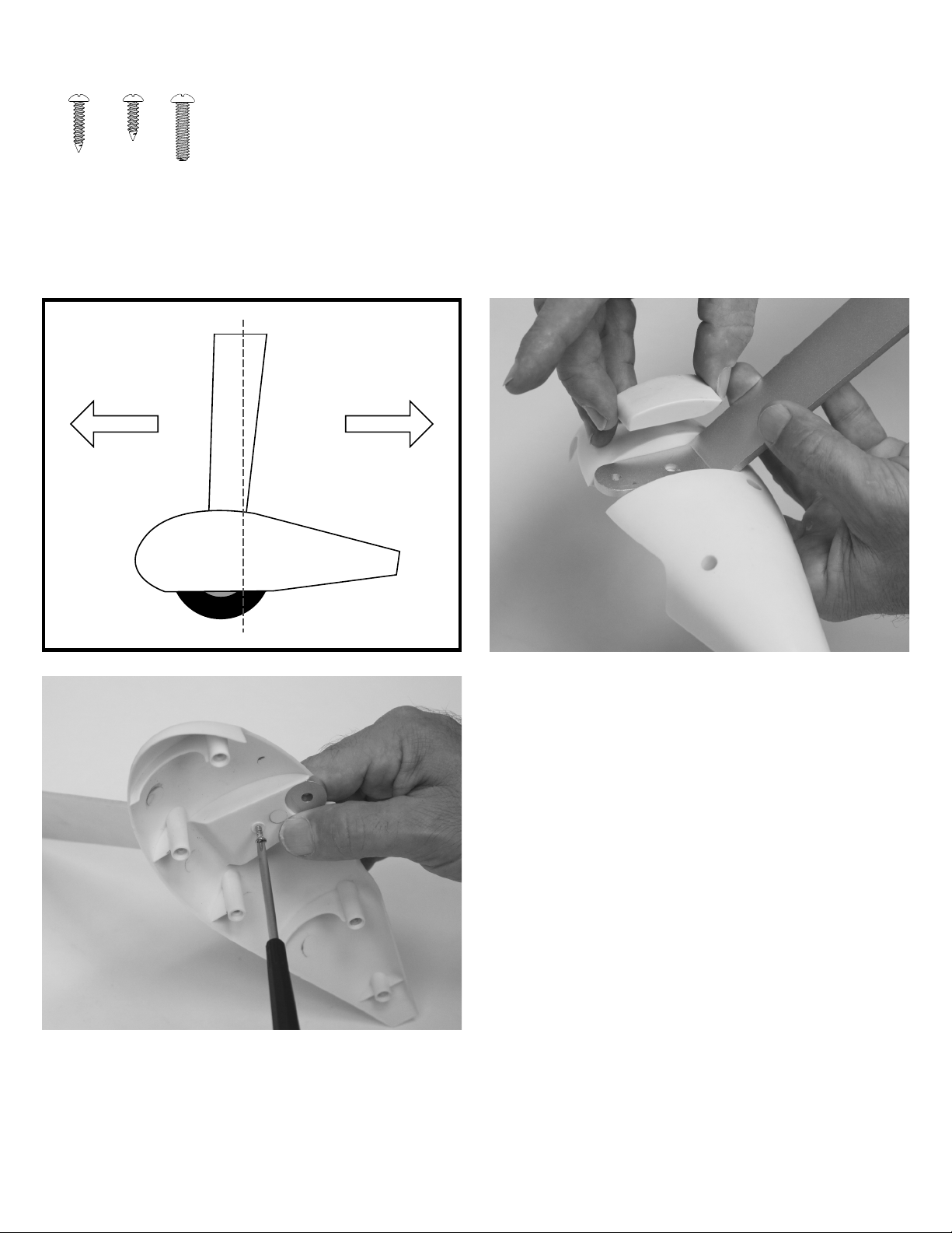
Locate the wheel pants, Use a #1 Phillips screwdriver to remove the screws from the wheel pants and separate the wheel pant halves
from each other.
Locate the landing gear. Place the inside half of the wheel pant against the outside of landing gear leg, and the wheel pant retaining
plate against the inside. Note that the retaining plates are identical. Use a #1 Phillips screwdriver and a M3x12 screw to secure the
wheel pant half in place. Be sure the landing gear and wheel pant are oriented in the proper direction.
5
(2) M3x12 Phillips Head Self-Tapping Screw
(10) M3x8 Phillips Head Self-Tapping Screw
(4) M3x20 Phillips Head Machine Screw
Blue Thread Lock
(QTY 2) (QTY 10)
Nose Tail
(QTY 4)
MAIN LANDING GEAR INSTALLATION (CONTINUED)
3.
4.
.
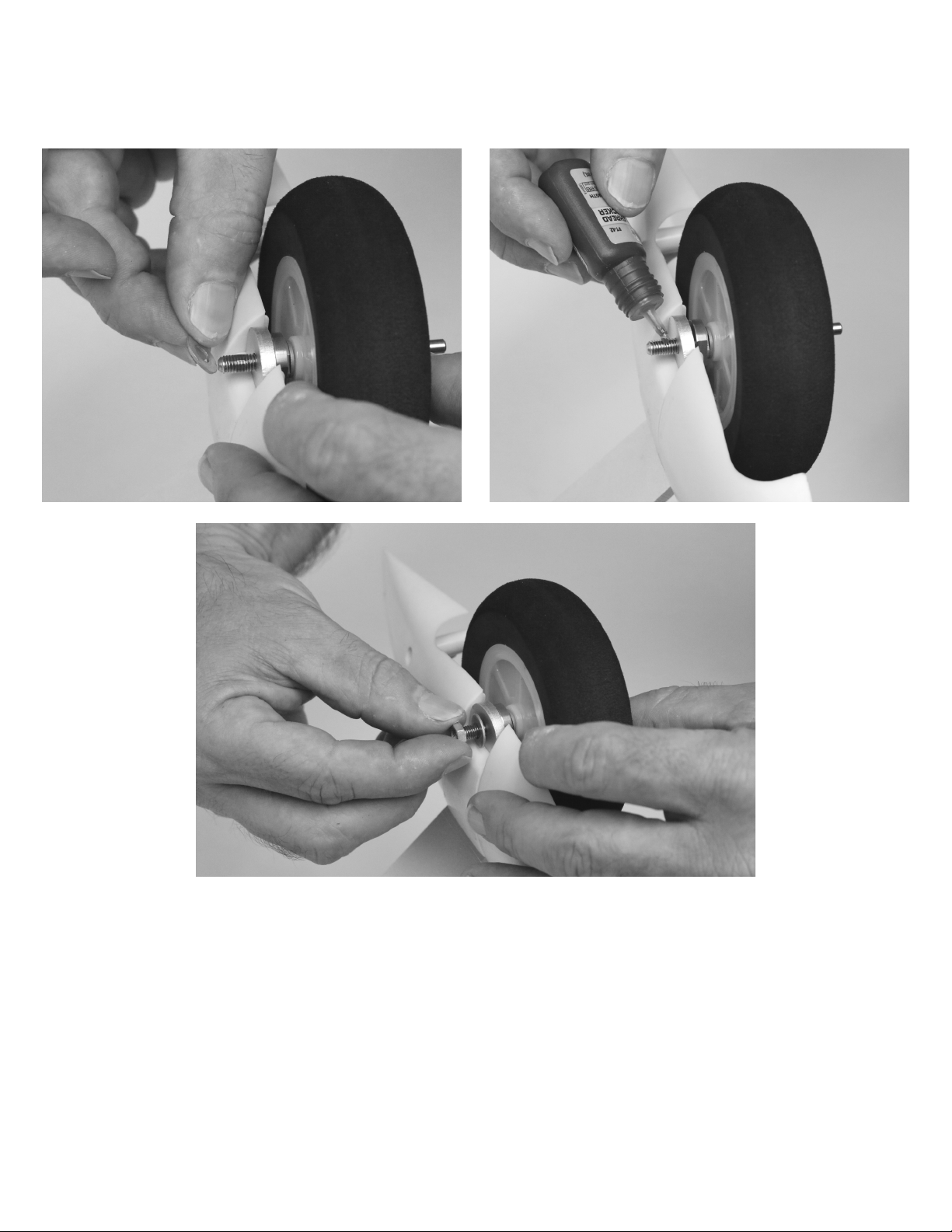
Locate the wheel and axle assembly. Use a 1.5mm hex driver to remove the set screws in the wheel collars. Apply blue thread lock to
the set screws and re-assemble.
Slide the threaded end of the axle through the landing gear from the outside of the landing gear. Place a washer over the axle and apply
blue thread lock to the axle threads. Secure the axle to the landing gear using an M5 nut and an 8mm and 12mm open end wrench.
6

MAIN LANDING GEAR INSTALLATION (CONTINUED)
6.
7.
Use a #1 Phillips screwdriver and five M3x8 self-tapping screws to secure the outside half of the wheel pant to the landing gear
assembly.
Apply blue thread lock to the four M3x20 machine screws. Use a #1 Phillips screwdriver and the four M3x20 screws to secure the
landing gear to the fuselage.
7

TAIL WHEEL INSTALLATION
Required Tools and Fasteners: #1 Phillips Screwdriver
(3) M3x7 Phillips Head Self-Tapping Screw
1.
2.
Locate the vertical fin assembly, tail wheel and tail wheel retaining plate. Insert the tail wheel into the bottom of the rudder, being sure to
orient it so that the tail wheel wire angles towards the tail as the wire moves away from the fuselage.
Insert the retaininig plate into the cavity on the bottom of the rudder. Use a #1 Phillips screwdriver and the three M3x7 self-tapping
screws to secure it in place.
8
(QTY 3)

VERTICAL FIN INSTALLATION
Required Tools and Fasteners: 30-Minute Epoxy
Craft Sticks (for mixing epoxy)
Mixing Cup
1.
2.
3.
Locate the vertical fin assembly and vertical fin tube. The vertical fin tube is the shortest tube included with your aircraft. Test fit the
vertical fin to the fuselage by inserting the tube into the vertical fin, and then into the fuselage. Confirm everything fits, and aligns
appropriately. Make any adjustments and test fit again until you are happy with the fit of the parts.
Use 220 grit sandpaper to scuff the vertical fin tube to prepare the surface for gluing. Use a paper towel and isopropyl alcohol to clean
the tube after scuffing. It is important to only scuff the tube. DO NOT remove a significant amount of material from the tube as it
can weaken the structure.
Use the craft sticks and mixing cups to mix an adequate amount of 30-minute epoxy. Apply epoxy to the vertical fin tube hole as well as
the fuselage parts that meet the vertical fin. Assemble the parts, being sure to wipe up any excess epoxy with a paper towel. Confirm
alignment, and wait for the epoxy to cure before proceeding to the next step. DO NOT use tape to secure the fin in place as it will
remove paint when it is removed.
9
220 Grit Sandpaper
Paper Towels
Isopropyl Alcohol

10
Description of Pre-Loaded Aura Flight Modes (FM)
Each of the modes has been tuned by our team to offer a solid start. Because tastes in control feel are unique, if changes in rates and
expo are needed, adjustments should be made through the Aura.
Changes in gain value can only be made through the Aura.
AURA 8 AFCS
Works conveniently with all major radio systems
Accepts signals from DSM Remote Receiver(s), Spektrum
SRXL, Futaba S.Bus, Graupner Hott (Sum D of 8), JR
XBus (Mode B), Jeti UDI12 (standard), Hitec S.Bus, PPM
Stream, or any brand of receiver via male to male servo
connectors
Expertly tuned and ready to use
USB port allows loading model configurations, user
programming, and firmware updates (cable included)
Flexible and extensive programming through Windows-
based PC or tablet
3+ flight modes allow precise or aggressive settings to be
selected in flight
3-axis gyro utilized in RV-8 programming
The Aura 8 Advanced Flight Control System (AFCS) installed in
your RV-8 is a giant leap forward in aircraft flight control system
technology. Compatible with virtually every receiver on the market
today, the Aura features special configuration for DSM systems via
remote receiver connection(s), and serial data connection for
Futaba or Hitec S.Bus, Spektrum SRXL, Graupner HOTT (Sum D
of 8), JR XBus (Mode B), and Jeti UDI12 (standard) systems, as
well as being compatible with traditional receivers via PWM servo
connections.
The Aura 8 advanced flight control system installed in your aircraft
has been pre-tuned for ease of use, eliminating many hours of
tedious setup. For the latest Aura features, programs, transmitter
downloads, and instructions, please visit wiki.flexinnovations.com/
wiki/Aura
The Aura is programmable through any Windows based PC or
tablet. All dual rate, expo, travel and assignable mode programs are
adjusted inside the Aura through the PC application. An assignable
master gain that is OFF by default can be enabled by the Aura
application. If desired, assign CH 8/AUX 3 on a proportional dial or
slider.
By default, CH5/Gear is used to select the 3 flight modes by 3
position transmitter switch. CH6/Aux 1 is used to manipulate the
flaps by 3 position transmitter switch. If you wish to control the
LED's in your RV-8 (Night Version only), you'll need to use a
standard receiver and plug the LED controller into an open channel
in your receiver.
Visit wiki.flexinnovations.com/wiki/Aura for the
latest Aura-related product information and
tips for your particular radio brand.
Mode 1 (Gyro Off):
Gyro gain is set to 0 (off). All rates are set to low for general flight (same as Sport Mode). Exponential is tuned for comfortable flight.
Mode 2 (Sport):
Gyro gains are moderate and tuned for comfortable feel/best performance for general flight. All rates are set to low for general flight.
Exponential is tuned for comfortable flight.
Mode 3 (High Rate/Live Wing Mode):
Gyro gains are moderate and tuned for general flight. Flaps work with aileron in roll. All rates are set to highest. Exponential is tuned for
comfortable flight.
REFERENCE ONLY: Aura Settings

TRANSMITTER SETUP
WARNING
The Aura 8 AFCS is designed to work seamlessly with all major transmitter and receiver brands. When programming your transmitter, start
with a freshly reset new model memory in your transmitter. Make ONLY the changes shown in the Transmitter Configuration Guide
unless otherwise noted.
The Aura 8 in your aircraft defaults to 3 flight modes that are switched via CH5/Gear in your transmitter. You may need to reassign CH5/
Gear to a 3-position switch.
The Night LEDs are switchable on/off via the transmitter. You will need to use a standard receiver, and plug the LED controller into an open
channel port in your receiver. You may need to reassign that channel in your transmitter to a 2-position switch.
Consult your transmitter manual if you have questions on how to change the switch or channel assignments.
The Aura comes pre-programmed with dual rates and expos specifically designed for your aircraft. For large (greater than 5%) changes in
expo or dual rates, it is highly recommended to reset all expos and rates to default in the transmitter, and tune through the Aura Config Tool.
The Aura Config Tool is free to download, and can be used on any Windows-based PC or tablet. Download at:
www.flexinnovations.com/AuraConfigTool
DO NOT ATTEMPT RADIO SETUP WITH PROPELLER INSTALLED. INADVERTENT POWER UP COULD CAUSE
DEATH OR SERIOUS INJURY.
11
TRANSMITTER CONFIGURATION GUIDE
End Points
(Travel Adjust
or ATV)
Ail/Ele/Rud
Thro/Gear/Flap
125%
100%
Sub Trim Verify at zero, NOT ALLOWED
Trim Levers Verify at zero
CH. 5 (Gear) Assigned to a 3-position switch
Reversing None Required2
Timer4
Wing/Tail Type 1 Aileron, 1 Flap, 1 Elevator, 1 Rudder
CH. 6 (Flap)
Spektrum, Futaba & Graupner JR DMSS1
Ail/Ele/Rud
Thro/Gear/Flap
Verify at zero, NOT ALLOWED
Verify at zero
Assigned to a 3-position switch
None Required
Set to 5:30 for initial flights
1 Aileron, 1 Flap, 1 Elevator, 1 Rudder
88%
88%
JR transmitter users that use Spektrum DSM2/DSMX receivers should follow the Spektrum information in the chart
above.
If you are using a Futaba transmitter, please note that some Futaba transmitters have the throttle set to reversed by
default. Leave reversing set to defaults to start, and reverse as needed.
This is only required to switch the LEDs on/off via the transmitter. If the LED controller is unplugged from the receiver
or Aura 8, the lights default in the ON position when powered.
This aircraft can fly anywhere between 5 and 9 minutes (w/6S 5200mAh Li-Po), depending on flying style.
1.
2.
3.
4.
NOTICE
FOR CUSTOMERS USING TRANSMITTERS OTHER THAN WHAT IS LISTED IN THE CHART ABOVE, PLEASE VISIT
OUR WIKI PAGE FOR INSTRUCTIONS SPECIFIC TO YOUR TRANSMITTER AND RECEIVER BRAND
JETI
HITEC
FRSKY
wiki.flexinnovations.com/wiki/Aura/JetiUse
wiki.flexinnovations.com/wiki/Aura/HitecSbusUse
wiki.flexinnovations.com/wiki/Aura/FrSkyUse
Use flap system, assign CH. 6 (Flap) to a 3-position switch
Set switch position values to 0% (neutral), -50% (takeoff), -100% (full flap)
Flap > Ele Mix Neutral - 0% | Takeoff - 17% Down Elevator | Landing - 17% Down Elevator
CONNECTING A BATTERY/ARMING THE ESC
12
1.
2.
3.
4.
Observe the following procedures to safely power up your model
after it has been bound. Ensure propeller is removed unless
sequence is followed to power up before flight.
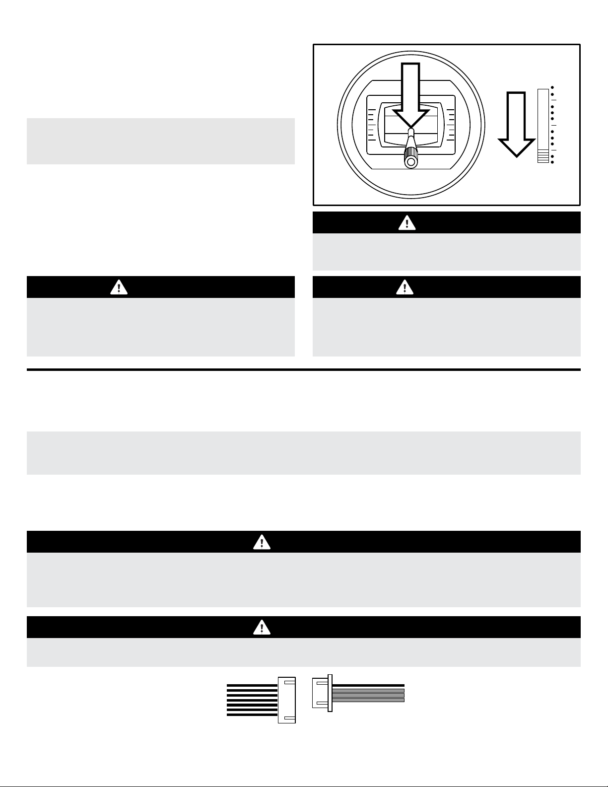
Lower the throttle stick and trim to their lowest setting and turn
on the transmitter. Wait for your transmitter to indicate the radio
signal is being broadcast before proceeding.
Ensure the aileron, elevator and rudder gimbals are centered.
With the airplane on a solid surface, connect the battery to the
ESC and wait. The ESC will make the motor emit a series of
audible tones during its intialization process.
The ESC will make the motor emit a short, final tone sequence
idicating that the ESC is now armed, and that the motor will spin
in response to throttle stick movement.
If a battery is connected to the ESC with the throttle fully
open on the active transmitter, the ESC will enter
programming mode. If this occurs, simply disconnect the
battery, lower the throttle, and reconnect the battery.
WARNING
When making adjustments to linkages,
transmitter settings or the Aura 8 flight control
system, remove the propeller to guard against
accidental spool up.
Hold the aircraft securely when connecting the
battery before flight. Always ensure the propeller
is clear of any and all objects as they may
become entangled.
WARNING
Always connect the battery when the throttle stick
and throttle trim is in the idle/cut-off position.
CAUTION
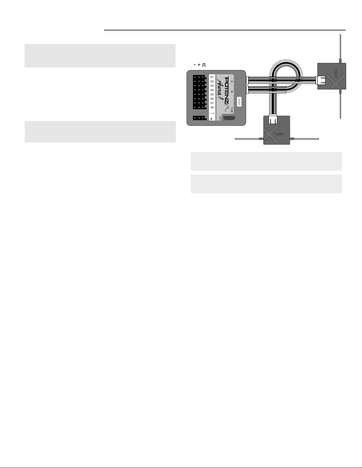
CONNECTING A BATTERY TO THE LED CONTROLLER (NIGHT VERSION ONLY)
The LEDs on your aircraft are switchable via the transmitter, and are designed to be powered by 12 volts (3S Li-Po) through the 6S JST-XH
balance tab on the LED controller. By default, the LED controller is left unplugged.
If the servo lead of the LED controller is not plugged into the Aura or a receiver, the LEDs will default in the ON position, allowing
the Night Version to be flown at night with a basic 6-channel transmitter or receiver.
The LEDs should be powered from a separate 3S Li-Po battery per the diagram below.
LED
CONTROLLER 3-6S Li-Po
WARNING
The LEDs draw approximately 2.5A from ONLY 3 cells of the battery powering it. If using a higher cell count battery for
power, 3 of the cells will have a lower voltage than the others at the end of each flight. Leave excess voltage in the battery
at the end of each flight to prevent the over-discharging of the cells that power the LEDs. You MUST balance charge your
batteries after each flight the LED controller is powered by anything other than a 3 cell battery.
WARNING
Do not leave the battery plugged into the LED controller for extended periods of time. Doing so can
damage the battery.
IN ORDER TO CONTROL THE LEDS FROM THE TRANSMITTER, YOU MUST USE A STANDARD RECEIVER THAT IS
CAPABLE OF 7+ CHANNELS, AND KEEPS THE SERVO PORTS ACTIVE WHEN USING A DIGITAL DATA STREAM
(like S.Bus, SRXL etc.).
RECEIVER INSTALLATION/SERVO CONNECTIONS
DEFAULT AURA CONNECTIONS
S1
S2
S3
S4
S5
S6
S7
S8
Throttle (ESC/BEC)
Left Aileron
Right Aileron
Elevator
Rudder
Left Flap
Right Flap
Float Water Rudder
Aura will auto-detect modern digital receiver connection(s). Using a
modern digital receiver connection gives the Aura access to precise
data of each channel for additional gyro-enabled outputs, simplifies
wiring, and allows for more advanced features. To connect a
modern digital receiver connection, follow the steps on this page,
then skip ahead to page 16.
For traditional PWM receivers without digital connection(s), male to
male servo leads must be used for each channel. Please refer to
the connection diagram on page 15.
Supported Modern Data-Linked Receivers
Connecting Your Receiver to Aura
Aura will auto-detect these modern digital receiver connections:
Spektrum Remote Receiver(s)
Futaba or Hitec S.Bus
Graupner HOTT (Sum D of 8)
Spektrum SRXL
JR XBus (Mode B)
Jeti UDI12 (standard)*
A PPM (8CH, negative shift, approximately 22ms/frame) receiver may also be
connected into Port 'B', however Aura will not auto-detect and setup must be
performed through the Aura Config Tool (Windows Application).
13
For specific information on receiver types and our
recommended receivers for this aircraft, please visit the RV-8
Wiki page at the below URL:
wiki.flexinnovations.com/wiki/RV8
Digital Receiver Connections
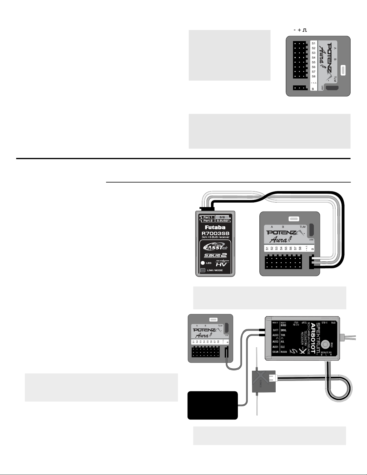
Note: If you are using Futaba S.Bus, be sure to use the proper
S.Bus port in your receiver. DO NOT use the S.Bus 2 port, as it
is not supported for use with the Aura 8. Refer to your
manufacturer's instructions for proper S.Bus use.
Note: When using Spektrum SRXL to connect to the Aura,
always connect the remote receivers to the Spektrum receiver,
NOT to the Aura.
While Spektrum and Futaba usually output their digital data
stream, it may be necessary for JR DMSS, Graupner HOTT,
and Jeti users to program the transmitter/receiver to output the
correct digital format listed on the previous page. Consult your
transmitter and receiver manuals for further details.
Bind your transmitter and receiver per your manufacturer's
instructions.
Connect the included male to male servo extension to the
receiver's data port (ex: S.Bus, SRXL etc.) and connect to servo
port 'B' on the face of the Aura. Refer to your radio
manufacturer's instructions for specific information on
appropriate serial port connections and system settings.
With the transmitter powered, power up the aircraft. Aura will
search (sweeping LEDs) and lock onto the signal. You will then
see solid orange (power and calibrated sensor) plus solid green
(valid radio source), and have control of the model.
1.
2.
3.
4.
If your receiver has a working throttle port while using it's
digital connection, USE IT. Move the ESC (throttle) lead from
Aura Port S1 to your receiver's throttle port. Consult your
receiver and/or transmitter instruction manual for specific
details on your system.
Examples of Recommended Receivers:
Spektrum SRXL
AR7700
AR8010T
AR9030T
JR XBus
RG612BX
RG712BX
Jeti UDI
EX R6i
EX R11
FrSky S.Bus
RX6R
RX8R
Futaba S.Bus
S-FHSS - R2001SB
FASST - R6303SB
FASSTest - R7008SB
Graupner SUMD
GR-12L
GR-16L
Hitec S.Bus
Optima SL-8
ESC
-+
-+
14
RECEIVER INSTALLATION/SERVO CONNECTIONS (CONTINUED)
If you are unsure which type of DSM remote receiver you
have, start by attempting the bind process with a bind plug
in S8. If you continue to have trouble binding, then insert
one bind plug in S1, and one bind plug in S8.
Note: It may be necessary to move the ESC lead to another open
port (such as 'Port B') during the binding precedure. Be sure to
return the ESC lead back to S1 after binding is complete.
Note: There are many JR-branded remote receivers that use
Spektrum DSM2 and DSMX RF protocol. For these, follow the
instructions as Spektrum remote receivers.
Connect (2) matching Spektrum remote receivers to Mini Port
'A' and Mini Port 'B' at the top of the Aura case.
To bind a DSMX Spektrum remote receiver connection, insert a
bind plug into Aura Port S8.
To bind a DSM2 Spektrum remote receiver connection, insert a
bind plug into Aura Port S1 AND S8.
Connect the flight battery to the ESC and the remote receivers
will begin to flash, indicating that they are ready to bind. Follow
the instructions provided with your transmitter to complete the
bind process.
Once bound (indicated by both remote receivers showing a
solid orange LED), Aura will begin the Auto-Detect process,
indicated by sweeping LEDs on the Aura. Once complete, you
will see a solid orange (power and calibrated sensor) and solid
green (Aura receiving valid receiver data) LED, indicating that
the Aura is in its flight ready state.
Mount your receivers using double sided foam tape or hook and
loop tape. Consult your receiver manual for proper mounting
orientations and procedures.
1.
2A.
2B.
3.
4.
5.
Please note, for optimum connection reliability and performance
using Spektrum, the Flex Team HIGHLY recommends the use of
a traditional receiver with SRXL (like the AR8010T or AR9030T).
Remote receivers may still be used, however.
Spektrum Remote Receivers

RECEIVER INSTALLATION/SERVO CONNECTIONS (CONTINUED)
1.
2.
3.
Bind your receiver to your transmitter by following the instructions provided by your transmitter and receiver manufacturer. Verify that it is
bound by connecting a spare servo to the receiver and verify that it responds to the appropriate input.
With the transmitter and receiver powerd OFF, connect your receiver to Aura using the diagram below. Note that the throttle is plugged
directly into the receiver, and other connections will need to removed per the diagram below. Depending on your particular transmitter,
you may need to reverse the throttle in the transmitter when the ESCs throttle lead is plugged directly into your receiver.
With the propeller removed and ALL connections made (observing correct polarity), power on your transmitter and the airplane with the
flight battery, ensuring that the airplane is kept stationary. After a few seconds, the LEDs on Aura will sweep back and forth as Aura
searches for a valid control signal. Once found, a solid orange (aura Running), and solid green (Aura receiving valid signal from the
receiver) LED is illuminated. After the source is found, apply transmitter right rudder to assist Aura to determine your radio type, after
which point control of the model is established. This is only required during initial setup
Connecting a Traditional Receiver to Aura with PWM Servo Connections
15
PWM is an acronym which stands for Pulse Width Modulation. A servo will move to a specific angle in a specific direction based on the
width of the signal pulse it receives. Most transmitters output a total pulse width of 1.1-1.9ms, with the midpoint being 1.5ms. Lower pulse
widths will move the servo to one side of neutral and higher pulse widths to the other side of neutral. Different from serial data connections
(S.Bus, SRXL etc.) this is how traditional receivers work. In order to utilize this type of receiver connection with your aircraft, male to male
servo leads to connect the corresponding receiver ports to Aura are required. A minimum 6-channel receiver is required to set up Aura with
PWM servo connections. Please purchase FPZAU01 Aura 3-piece male to male servo cable/S.Bus to complete the PWM connection
setup.
NOTICE
VERIFY PROPER POLARITY OF ALL CABLE CONNECTIONS PRIOR TO ADDING POWER TO THE SYSTEM
All four (4) PWM male to male connections must be connected AND connected in the proper polarity from receiver outputs
to Aura inputs for Aura to activate servo outputs. (Aileron - S1, Elevator - S2, Rudder - S3, Gear/CH5 - S4)
RX
Thro
Ail
Ele
Rud
Gear (CH5)
Aux 1 (CH6)
Aux 2 (CH7)
S1
S2
S3
S4
S5
S6
S7
S8
Receiver
PWM Inputs
Servo PWM
Outputs
LED
CONTROLLER
Servo Lead
Plug Into Open
RX Channel
To LED
Battery
Rudder Servo
Float Water Rudder Servo
Elevator Servo
Right Aileron Servo
Left Aileron Servo
Right Flap Servo
Left Flap Servo
ESC
Throttle
Lead
To Motor
Note: The LEDs on the RV-8 Night Version are able to be turned on and off via a channel from your transmitter. Simply plug the servo
lead from the LED controller following the diagram above and assign that channel to a 2-position switch on your transmitter accordingly.
If you do not have an available channel on your transmitter and/or receiver for the LED controller, you can simply leave the
servo lead unplugged, and the lights will be on by default (once powered). Be sure to secure the wiring to the fuselage.
If you are using a traditional Spektrum receiver, with remote receivers, DO NOT plug any remote receivers into the
Aura 8. They should instead be plugged directly into your traditional receiver.
Y-Harness
(FPZA1012)
*Y-Harness
(FPZA1012) *Servo Reverser
(FPZA1025)
* Y-Harness and Servo Reverser is not required if using a 7+ channel transmitter and receiver (or 8+ if you want switchable LEDs) with dual flap servo and independent servo reversing capability.
** Arrows indicate signal (data) flow. They do not necessarily indicate voltage (+) flow.

HORIZONTAL STABILIZER INSTALLATION
Required Tools and Fasteners: #1 Phillips Screwdriver
Blue Thread Lock
1.
2.
3.
Insert the horizontal stabilizer tube into the fuselage and roughly center.
Slide the left and right sides of the horizontal stabilizer onto the tube. Ensure the control horn orients to the bottom of the fuselage and
that the elevator joiner tabs are indexed properly. Do not force the stabilizer into place.
Use a #1 Phillips screwdriver and two M3x8 Phillips head self-tapping screw to secure each stabilizer in place.
16
(4) M3x8 Phillips Head Self-Tapping Screw
(QTY 4)
1
2

RUDDER AND ELEVATOR LINKAGE INSTALLATION
17
Required Tools and Fasteners:
Locate the rudder and elevator pushrod assemblies, as well as the servo arms and hardware. Note that both pushrods and servo arms
are the same length.
Power on your transmitter, and move your Flight Mode switch (assigned on page 11 of this manual) to Mode 1 (Gyro Off). Power on the
airplane, and confirm the Aura is in Mode 1 by rotating the airplane quickly, and verifying that you get no gyro controlled servo
movement.
With the aircraft still powered on, install the rudder and elevator servo arms perpendicular to the servo case, being sure to orient the
servo arm torwards the bottom of the fuselage. Apply blue thread lock to the M3x6 phillips head machine screw, and secure the servo
arm in place with a #1 Phillips screwdriver.
1.
2.
3.
Elevator and Rudder Pushrod Assemblies
M2x10 Phillips Head Machine Screw (4)
M2 Flat Washer (4)
M2 Lock Nut (4)
M3x6 Phillips Head Machine Screw (4)
#1 Phillips Screwdriver
#0 Phillips Screwdriver
Needle-Nosed Pliers (or Hemostats)
Blue Thread Lock
WARNING
DUE TO VARIANCES IN PRODUCTION AND THE LARGE CONTROL SURFACE THROWS ON THIS AIRCRAFT,
PROPER SERVO CENTERING AND TRAVEL ADJUSTMENT IS CRITICAL TO PREVENT SERVO OVER TRAVEL
AND FAILURE. IF THE SERVO ARMS ON YOUR AIRCRAFT DO NOT SIT PERPINDICULAR TO THE SERVO
CASE, YOU MUST USE THE AURA CONFIG TOOL TO ADJUST THE SUB-TRIM AND OUTPUT SCALE VALUES
TO PREVENT OVER TRAVEL OF THE SERVOS.
To download the Aura Config Tool, please visit:
https://www.flexinnovations.com/articles.asp?ID=257
(QTY 4) (QTY 4) (QTY 4) (QTY 4)

RUDDER AND ELEVATOR LINKAGE INSTALLATION (CONTINUED)
18
Use a #0 Phillips screwdriver, M2x10 machine screw, M2 washer and M2 lock nut to secure the linkage to the control horn and servo
arm. Use the chart below for proper control horn and servo arm linkage locations. The order of components is as follows:
M2x10 Machine Screw
M2 Washer
Servo Arm or Control Horn
M2 Lock Nut
Repeat the process for the other control linkage.
4.
5.
Servo Arms
Elevator Rudder
Control Horns
Elevator Rudder
Prototype shown. Control horn location is
not correct. Reference the chart above.
Table of contents


