Flexit C2 User manual

ART. NO.:
700030
700031
700032
700033
C2
114529EN-05
2016-11
Assembly Instructions
Ceiling mounted air handling unit
and automatic control system
INSTALLATION
INSTRUCTIONS

2
This appliance may be used by children of 8 years or
above or by persons with reduced sensory capacity
or reduced physical or mental capacity, or by persons
with lacking experience or knowledge, provided they
have received instructions in the safe use of the
appliance or are supervised to ensure safe use and
providing they are aware of the risks. The product is
not suitable for use by children.
Children must not be allowed to play with the
appliance. Children must not carry out cleaning or
maintenance without supervision.
Our products are subject to continuous development
and we therefore reserve the right to make changes.
We disclaim all liability for printing errors.
See the following documents for more
information on the product:
114531 Spare parts list
114537 Wiring diagram without electric battery
114536 Wiring diagram with electric battery
110827 CI60
110828 CI600
SAFETY INSTRUCTIONS
• It is the installer's responsibility to
carry out a full safety and function
assessment of the appliance.
• To reduce the risk of fire, electric
shock or injury, read all the safety
instructions and warning texts before
using the unit.
• This unit is only designed for
ventilation air in homes and
commercial buildings.
• It must not be used to extract
combustible or flammable gases.
• Remove the power plug before
commencing any service and
maintenance work.
• Before opening the door: switch off
the heat, let the fans continue for
3 minutes to remove hot air, unplug
the unit and wait 2 minutes before
opening the doors.
• If the power cable is damaged, it must
be replaced by the manufacturer,
the manufacturer's service agent or
a similarly qualified person.
• The unit contains heating elements
that must not be touched when they
are hot.
• The unit must not be operated
without the filters being in place.
• Do not heat any combustible
substances under the cooker hood if
one is installed.
• Do not leave a saucepan or frying
pan containing oil or fat unsupervised
when using a cooker hood.
• Warranty claims will only be valid if
the instructions in the manuals have
been followed.
• To maintain a good indoor climate,
comply with regulations and avoid
condensation damage, the unit
must never be stopped except
during service/maintenance or in
connection with an accident.
• All electrical connections must be
carried out by qualified electricians.
• All plumbing work must be carried out
by an authorised plumber.
• The water battery must be located in
a room with a drain.
When servicing ceiling-mounted units, be aware of the
danger of components falling down.

3
Innhold
1 How to read the document....................................................................................................................................... 4
2 Planning and preparation work....................................................................................................................5
2.1 Joiner / fitter ...........................................................................................................................................................................................5
2.2 Plumber (if the unit has a water battery)................................................................................................5
2.3 Electrician...................................................................................................................................................................................................5
3 Installation........................................................................................................................................................................................................ 6
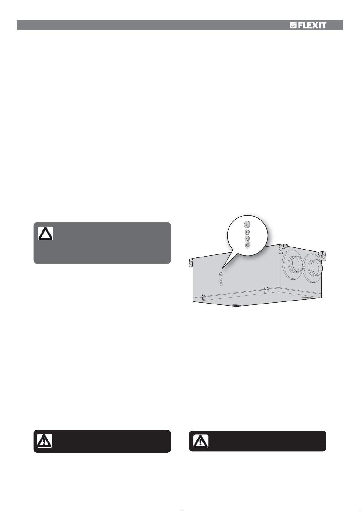
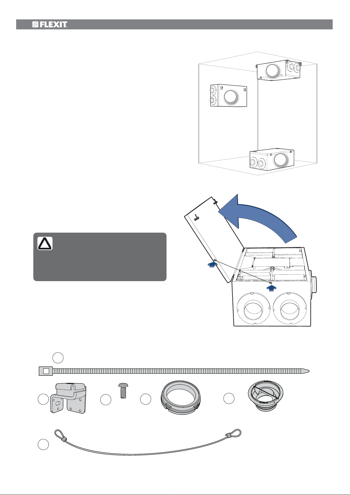
3.1 Mounting the safety strap................................................................................................................................................ 6
3.2 What is supplied?........................................................................................................................................................................... 6
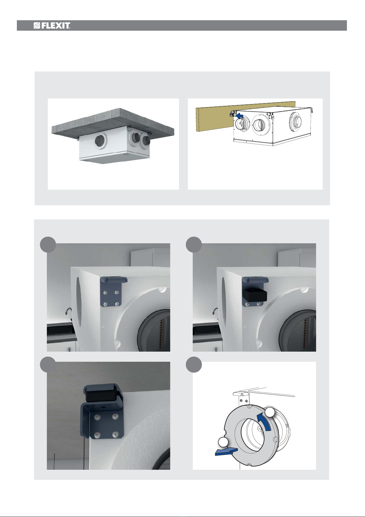
3.3 Ceiling mounting..............................................................................................................................................................................7
3.4 Wall mounting...................................................................................................................................................................................13
3.5 Floor (attic) mounting.........................................................................................................................................................15
4 Duct connection.............................................................................................................................................................................. 16
4.1 Connection to the unit ...................................................................................................................................................... 16
5 Installation of the CI60/600 control panel.................................................................17
5.1 Contents......................................................................................................................................................................................................17
5.2 Installation of the CI60/600...................................................................................................................................17
5.3 Installation with a flush-mounted wall box.......................................................................................18
5.4 Surface mounting..................................................................................................................................................................... 18
5.5 Finishing off – C160................................................................................................................................................................ 18
5.6 Finishing off – C1600.......................................................................................................................................................... 18
6 Electrical work...................................................................................................................................................................................... 19
6.1 Supply air sensor for heating (B1) .................................................................................................................. 19
6.2 Frost sensor for water battery (B5) (if the unit has a water battery).... 19
6.3 Outdoor air damper (if the unit has a water battery)...................................................... 19
7 Plumbing work*.................................................................................................................................................................................. 19
8 Adjustment................................................................................................................................................................................................. 20
8.1 Adjustment with CI60......................................................................................................................................................... 20
8.2 Adjustment......................................................................................................................................................................................... 20
8.3 Adjusting the temperature....................................................................................................................................... 20
8.4 Adjustment with CI600 ................................................................................................................................................... 21
9 Installing the cooker hood...................................................................................................................................22
9.1 Installation of external cooker hood..........................................................................................................23
9.2 Adjusting the cooker hood.......................................................................................................................................23
10 General and system drawings.................................................................................................................24
10.1 System drawing (electric battery)................................................................................................................24
10.2 System drawing (electric battery)..............................................................................................................25
10.3 Nipple location...........................................................................................................................................................................26
11 Technical data...................................................................................................................................................................................27
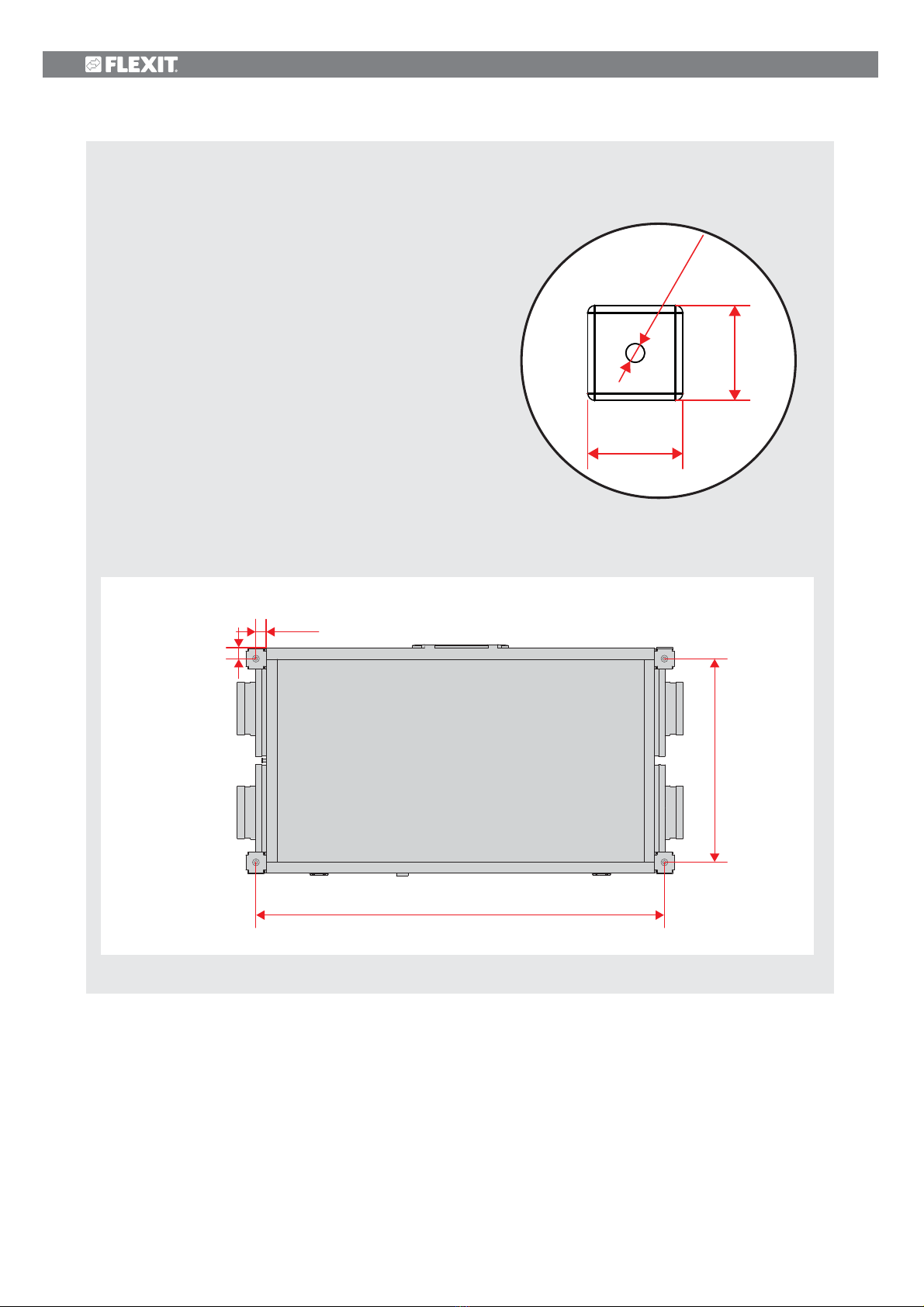
11.1 Dimensioned drawing......................................................................................................................................................... 28
11.2 Capacity and sound data...........................................................................................................................................29
12 Final checks / Startup..................................................................................................................................................32
12.1 Final checks....................................................................................................................................................................................... 32
12.2 Startup....................................................................................................................................................................................................32
13 CE Declaration of Conformity................................................................................................................... 33

4
1 How to read the document
DANGER! DO NOT TOUCH
Symbols used
These products have a number of symbols that are used
to label the product itself and in the installation and user
documentation.
Extract air Extract
air from
kitchen
Outdoor air
Supply air
Exhaust air
CAUTION! When a text bears this
symbol, it means that personal
injury or serious damage to the equip-
ment may result if the instructions are
not followed.
NB! When a text bears this sym-
bol, damage to equipment or
poor efficiency may be the consequen-
ce of not following the instructions.
DANGER!
ELECTRICITY

5
2 Planning and preparation work
2.1 Joiner / fitter
Airflow
Check that the air moves from rooms with supply air
valves to rooms with extract air valves.
Kitchen
If a kitchen fan with a motor is included, sufficient
supply air must be ensured. See Chap. 9.1 Installation
of external cooker hood and Chap. 9.2 Adjusting
the cooker hood for more information.
Fireplace
When using a fireplace, sufficient air supply from
a separate supply air point must be ensured.
Location in the building
Location of the unit on an internal wall requires
insulation of the wall, interrupted studs and boards,
and double plasterboard or a wall structure of similar
quality (see Chap. 3.4.1 Positioning requirements).
Suspension of unit
See kap. 3 Installation på side 6.
Access
The unit must have good access for service/
maintenance. See kap. 3 Installation på side 6
for details.
Fire requirements
Any fire safety requirements must be clarified.
Location of heat sources must be coordinated with
extraction valves, so that heat is not sucked straight
out through the valves or door gaps.
2.2 Plumber (if the unit has a water battery)
Water pipe layout and location of the water battery
(duct battery) must be planned. These must be kept
warm to avoid frost damage. A closing damper with
spring must be used. See separate instructions that
accompany the water battery.
2.3 Electrician
Power supply
The units have an approx. 2 m cable with plug and
require a single-phase earthed socket nearby. Plug
requirements: 10 A. We recommend a separate circuit
for the unit. It is important that the plug is accessible
for servicing when the unit is fully installed.
If a cooker hood is to be connected to the ventilation
unit, a minimum Ø16 conduit must be installed for the
two-core signal cable.
NB!
The PG nipple for the power cable must be tightened
with a torque of 2.0 Nm if the cable is replaced.
For exact positioning of the electrical bushings,
see 11.1 Dimensioned drawing.
The assembly instructions for the
product must be followed.
Wiring for control switches.
Ø20 conduit for running the trailing cable for
controlling the unit should be laid between the
unit and an easily accessible place in the home
(e.g. outside the bathroom) and terminated with
a flush-mounted single wall box. The control switch
is located here. The control cable must be located
min. 30 cm away from any power cables. The control
cable must be max. 24 m to ensure a signal.
Control panel
The control panel is designed for flush mounting over
a single wall box or surface mounting on the wall.
figure 1
Positioning of bushings for
electrical conductors.
The water battery must be
located in a room with a drain.
Positioning must accord with
individual countries' electrical
safety legislation. Check which
rules apply in your country.

6
3 Installation
The unit can be installed in the following ways:
• On the ceiling.
• Horizontally on a wall.
Mounting devices for this can be purchased as
an accessory.
• On the floor (lying on its back).
In this case absorption feet are recommended
(available as an accessory).
The unit comes in both a left-hand and a right-hand
version, depending on what is best with regard to duct
positioning.
figure 2
Location options
1
2
3
3.1 Mounting the safety strap
Mount the safety strap as shown on figure 3.
figure 3
Fixed safety strap
When the unit is located on the
floor, this strap must always be
mounted.
We also recommend its use for
ceiling mounting.
5x
4x 1x 1x16x
1x
A
BCDE
Ffigure 4
What is supplied?
3.2 What is supplied?

7
3.3 Ceiling mounting
3.3.1
Positioning requirements
The unit is designed to be installed in boiler rooms,
laundry rooms, stores, lofts or other suitable areas.
The unit should be positioned in such a way that there
is no danger of noise nuisance in nearby rooms.
If the unit is located in a warm room where a lot of
moisture is generated, condensation may form on the
outside of the unit during periods when the outside
temperature is low.
The base should be stable and level.
3.3.2
Space requirements
The unit must be installed with suitable space for
servicing and maintenance such as filter replacement
and cleaning of fans and recovery system.
See figure 5. The control cable with plug for
automatic control must be easily accessible when the
unit is fully installed.
These are minimum requirements and only take
service needs into account.
figure 5
Space requirements for ceiling mounting
figure 6
Opening the door in case of ceiling mounting
530mm
400mm
400mm
200mm
*
In the case of mounting in an
enclosure or a suspended ceiling,
remember that the door must be
able to open by 120°.
Ensure there is servicing access
to electrical bushings. See the
dimensioned drawing for exact
location.
Positioning must accord with
individual countries' electrical
safety legislation. Check which
rules apply in your country.
* required
for access to
electrical bushings

8
Fixing brackets to be mounted in the same way regardless of top or side mounting
1 2
43
The air handling unit can be mounted in the ceiling in several different ways.
Alternative 1 - Top mounting Alternative 2 - Side mounting
To facilitate access to the fixing bracket,
the polystyrene rings round the bosses
may be removed.
3.3.3
Mounting of fixing bracket
1
2

9
Alternative 1 - Top mounting
3mm
The unit must always
be mounted at
min. 3mm distance
from the mounting
substrate, as shown in
figure 12. This is to
prevent structural
sound.

10
Alternative 1 - Top mounting
If it is necessary to pre-drill your mounting substrate,
the drilling pattern is given here:
Select a suitable fixing device which matches your mounting
substrate.
Remember that the unit weighs 46 kg and the fixing device
must be able to support this.
40 mm
40 mm
Ø8 mm
472mm
947mm
26mm
24mm
figure 7
Hullbilde topp

11
Alternative 2 - Side mounting

12
Alternative 2 - Side mounting
Select a suitable fixing device which matches your mounting substrate.
Remember that the unit weighs 46 kg and the fixing device must be
able to support this.
If it is necessary to pre-drill your mounting substrate, the drilling
pattern for the two mounting alternatives is given here:
figure 8
Hole pattern at side
46 mm
947 mm
524-550 mm
49 mm
8 mm
14 mm
18,5 mm
Ø5 mm
figure 9
Make sure the mounting
substrate only touches
the fixing brackets and
not the unit.
This is to prevent
structural sound.
The fixing bracket can
therefore be adjusted
sideways in both
directions to avoid this.

13
3.4 Wall mounting
3.4.1
Positioning requirements
The unit is designed to be installed in boiler rooms,
laundry rooms, stores, lofts or other suitable areas.
The unit should be positioned against a wall that
has no room on the other side that is sensitive to
noise. The wall should be soundproofed, e.g. with
mineral wool, to reduce the transfer of sound.
Double plasterboard on the wall, interrupted studs
and interrupted plasterboard are recommended.
See figure 10.
If the unit is located in a warm room where a lot of
moisture is generated, condensation may form on the
outside of the unit during periods when the outside
temperature is low.
The base should be stable and level.
BOILER ROOM
BOILER ROOM
LIVING ROOMS
LIVING ROOMS
suitable
insulation
figure 10
Recommended wall construction
figure 11
Recommended direction
See separate instructions
for mounting the wall fixing.
Positioning must accord with
individual countries' electrical
safety legislation. Check which
rules apply in your country.
Mounting devices for this can be
purchased as an accessory.

14
figure 12
Space requirements for wall
mounting
figure 13
Space requirements for wall mounting
400mm
400mm
Ensure there is servicing access
to electrical bushings. See the
dimensioned drawing for exact
location.
* required
for access to
electrical bushings
200 mm*
min 90°
3.4.2
Space requirements
The unit must be installed with space for servicing and
maintenance such as filter replacement and cleaning
of fans and rotary heat exchangers. The control
cable with plug for automatic control must be easily
accessible when the unit is fully installed.
These are minimum requirements and only
take service needs into account.

15
3.5 Floor (attic) mounting
3.5.1
Positioning requirements
The unit is designed to be installed in boiler rooms,
laundry rooms, stores, lofts or other suitable areas.
When installing on the ceiling, absorption feet should
be used, for the sake of noise and vibrations. Flexit
offers suitable absorption feet as accessories, see
figure 15. The unit should be positioned in such a way
that there is no danger of noise nuisance in nearby
rooms. It is especially important not to position the
unit directly above bedrooms.
If the unit is located in a warm room where a lot of
moisture is generated, condensation may form on the
outside of the unit during periods when the outside
temperature is low.
3.5.2
Space requirements
The unit must be installed with space for servicing and
maintenance such as filter replacement and cleaning
of fans and rotary heat exchangers. The control
cable with plug for automatic control must be easily
accessible when the unit is fully installed.
The base should be stable and level.
These are minimum requirements and only
take service needs into account.
figure 14
Space requirements for ceiling (floor) mounting
figure 15
Absorption feet
530mm
200mm*
400mm
400mm
Floor-mounted units must always
be fitted with a safety strap.
Ensure there is servicing access
to electrical bushings. See the
dimensioned drawing for exact
location.
Positioning must accord with
individual countries' electrical
safety legislation. Check which
rules apply in your country.
* required
for access to
electrical bushings

16
4 Duct connection
4.1 Connection to the unit
See figure 16.
Ensure that the ducts are fitted to the correct nipple -
see the markings on top of the unit and kap. 10
General and system drawings på side 24
Pull the duct insulation well up to the unit.
To avoid the formation of condensation, it is
particularly important for the outdoor and exhaust air
ducts to have insulation and a plastic sleeve pulled
right down to the unit. Seal the plastic sleeve against
the unit with ties.
All ducts that pass through a cold zone must be
insulated.
The ducts normally require min. 50 mm insulation, with
an efficiency corresponding to Ȝ 0.035 W/m.°C or
The duct insulation with plastic jacket is
pulled right down to the polystyrene around
the nipple. It is very important that there are
no gap between the duct insulation and the
polystyrene, as this could lead to condensation
and/or the formation of ice.
Pull the spiral pipe well down over the seal on
the nipple.
The plastic sleeve is pulled right down to the unit.
Fix the sleeve with ties.
figure 16
Duct connection
3
4
2
1
better.
The project engineer is responsible for use of the
required insulation and vapour-proof sleeves in
accordance with location/temperature.
Lay the outdoor air duct with a slight fall towards the
outdoor air cap so that any water that enters drains
out again.
Ducts should have good sound insulation, particularly
above the unit.

17
The control units must be
connected to the unit before
power is connected to the unit in
order to ensure communication.
The low-voltage cable must be at
least 30 cm from power cables
and not exceed 24 m in length.
In the case of flush mounting the
cable is run in a 20 mm wiring
conduit.
Configuration Setting
CI 600 (MASTER)
CI60 1 (SLAVE)
CI60 2 (SLAVE)
Automatic
OFF
ON
CI60 1 (MASTER)
CI60 2 (SLAVE)
OFF
ON
CI 600 (MASTER)
CI60 (SLAVE)
Automatic
Any
5.2 Installation of the CI60/600
Run the cable for the control panel between the
ventilation unit and the control panel. The control
panel is designed for flush mounting over a single wall
box (use low backpiece (2)) or for surface mounting
on the wall (use high backpiecee (3)).
The cable clicks into the contact on the control panel
from the back and into the contact on the top of the
ventilation unit.
It is possible to connect two CI60 panels and one CI600
panel to each unit. If several CI60 panels are used,
each panel must have a separate identity. This can be
selected by means of a switch on the panel's circuit
board, see figure 18. Use relevant settings from the
table. The panels can be connected in series in any way.
OFF = MASTER
ON = SLAVE
1
2
3
4
5
5 Installation of the CI60/600 control panel
5.1 Contents
ON OFF
Control panel
Backplate for flush mounting
Backplate for surface mounting
Installation instructions
Cable for control panel
figure 17
Contents control panel
figure 18
Switch circuit board

18
5.3 Installation with a flush-mounted wall box
Run the cable between the wall box and the ventilation
unit in the pre-installed wiring conduit. Fit the backplate
(2) over the wall box and click the cable in straight
from the back as shown in the illustration,
see figure 19.
5.4 Surface mounting
Run the cable between the backplate (3) and the
ventilation unit. Cut out the most suitable perforation
in the corner of the backplate. Secure the backplate
to the wall with suitable screws. Click the cable into the
control panel from below where there is a socket in
the circuit board, see figure 22.
5.5 Finishing off – C160
Slide the panel off in the direction of arrow no. 1, see
figure 20, and guide the control panel straight into
the backplate, in the direction of arrow no. 2 see
figure 21, until it clicks into place. Slide the panel back
on.
5.6 Finishing off – C1600
Guide the control panel over the hooks in the backplate,
in the direction of arrow no. 1 and click the panel into
place at its lower edge in the direction of arrow no. 2
see figure 23.
figure 19
Installation of flush-mounted wall box
1
1
1
1
2
2
2
2
figure 20
figure 21
figure 22
Surface mounting
figure 23
Finishing off

19
The plug for the unit must not be
boxed in.
Temperature sensor B1 must be
positioned after the water
battery
The control cable must be max.
24 m long. It must be at least
30 cm from power cables and
should be laid in a 20 mm wiring
conduit at installation.
The unit must be installed with
a separate earth fault breaker.
All electrical connections must
be carried out by qualified
electricians.
6 Electrical work
The unit is supplied with a 2 m cable with plug.
The cable exits the long side of the unit and is
connected to a 230 V 50 Hz single-phase earthed
power point that is placed in an easily accessible
position close by. The power plug should be used as
the service switch. See kap. 11 Technical data på
side 27 for fuse sizes.
The control panel is designed for flush mounting over
a single wall box or for surface mounting on the wall.
The unit has a control cable (with joint) that is
intended for the control panel. It is important that
this plug is easily accessible afterwards for possible
faults, or when changing the unit. The control cable is
enclosed in the packaging for the control panel.
The control panel is in a box in the unit's packaging.
The low-voltage cable must be run between the unit
and the switch unit. See kap. 5 Installation of the
CI60/600 control panel på side 17.
6.1 Supply air sensor for heating (B1)
This must be located in the supply air duct.
• Where electric heating is retrofitted,
the supply air sensor must be
mounted in the supply air nipple.
• When mounting a water battery,
the supply air sensor must be
positioned approx. 1 m from the water battery.
Roll out the marked coil of cable on the unit near
the supply air nipple. Drill a Ø 7 mm hole in the
duct where the sensor can be inserted. Seal the
hole with sealant and tape the cable in place on
the outside of the duct so that it stays in place.
See the wiring diagram enclosed with the unit
and the instructions that come with the water
battery.
6.2 Frost sensor for water battery (B5)
(if the unit has a water battery)
To avoid frost in the battery, a water battery sensor
(B5) must be installed in the water battery pipe where
the cold water leaves the battery.
For more information, see instructions for water
battery.
6.3 Outdoor air damper (if the unit has
a water battery)
To avoid frost damage to the water battery during
outages/power cuts, a closing damper must be
installed on the outdoor air duct. The damper motor
must have a spring so that it closes when power is
disconnected.
7 Plumbing work*
*If the unit is designed for heating with a water battery.
All plumbing work must be carried out by an
authorised plumber. See instructions for water battery.

20
The unit's air supply MUST be
adjusted before the unit is used
for the first time. This should be
done in accordance with the
project engineering documents.
Adjust the values according to
the projected values.
figure 24
Adjustment
8 Adjustment
8.1 Adjustment with CI60
8.2 Adjustment
Only stage 2 (NORMAL) needs to be adjusted. Stages
1 and 3 have fixed settings, while stage 2 must be
adjusted as required in the individual home.
The function of the different stages:
MIN Must not be used when the home is in
use. Must not be used in the first year of
operation.
NORMAL Used under normal conditions. With this
setting, the air supply must be adjusted
according to current regulations.
MAX Used if there is a need for increased air
supply on account of higher occupancy
or a raised humidity level, for example
during showering or when clothes are
being dried. This setting is normally used
for limited periods.
The ventilation unit's air supply is adjusted at speed
level NORMAL, using the knobs on the back of the
cover. Knob 9 is used for supply air level and knob 8
for extract air level, see figure 24. The adjustment
range is 20-100% of the maximum level according to
the scale on the knob.
Factory settings for supply air/extract air:
MIN 50% (fixed)
NORMAL 75% (variable)
MAX 100% (fixed)
8.3 Adjusting the temperature
The temperature required for the supply air can be
set with knob 11. The adjustment range is 10-30°C.
It should normally be set to around 18°C. Use of the
factory setting is recommended.
8
9
10 11
If necessary, the ventilation unit's additional heating
can also be switched ON/OFF with switch 10. In this
case only the rotary heat exchanger is used as a
source of heat. It is best to leave it in ON position,
as the unit will then respond automatically when there
is a need for additional heating.
Other manuals for C2
1
This manual suits for next models
4
Table of contents
Popular Air Cleaner manuals by other brands

Figure Machine
Figure Machine XLFLOW-STACK installation manual

Baileigh Industrial
Baileigh Industrial AFS-1000 Operator's manual

Honeywell
Honeywell HFD-010 - Room Air Purifier owner's manual

EnviroPureFX
EnviroPureFX EPFX HEPA550-3 owner's manual

Aerus
Aerus LUX GUARDIAN ANGEL manual

Zass
Zass ZAP 01 user manual