Flexiva PM3K350 User manual

User Manual
PM3K350
Bidirectional 3.5 kW DC/DC Converter Module
Article No.: BNH-PM3K350
Date of edition/rev.: 17.04.2012

User Manual DC/DC Module PM3K350
Preface
Flexiva automation & Robotik GmbH
Weißbacher Straße 3
D – 09439 Amtsberg
2
Preface
The present Technical Documentation is to inform of the correct operation of the
DC/DC converter modules PM3K350. The modules serve to convert direct voltages in
a bidirectional way.
The operating manual is to be preserved.
It is prohibited to copy or duplicate texts, plans, and tables or to make them
accessible to any third parties without our express consent.
We draw your attention to the fact that the Technical Documentation shall not be part
of an existing earlier agreement or promise or part of a legal relationship.
All and any obligations result from the purchase contract that also solely contains the
warranty determination. The contractual provisions shall not be affected by the
Technical Documentation.
The documentations of the suppliers used shall apply along with the present
documentation of the manufacturer.
In addition to the operating manual, all universally valid legal and other obligatory
regulations concerning the prevention of accidents and the environmental protection
are to be complied with and to be instructed.

User Manual DC/DC Module PM3K350
Introduction
Flexiva automation & Robotik GmbH
Weißbacher Straße 3
D – 09439 Amtsberg
3
Table of Contents
1Introduction............................................................................................................... 6
2Identification ............................................................................................................. 7
2.1 Product Trademark and Type Designation ........................................................ 7
2.2 Product Version / Version of Software / Editing State........................................ 7
2.3 Declaration of Conformity with the Product Standards ...................................... 8
3Product Description ................................................................................................. 9
3.1 General Information / Utilization as Directed...................................................... 9
3.2 Technical Information and Data....................................................................... 10
3.3 Power Terminals.............................................................................................. 12
3.4 Signal Connections.......................................................................................... 13
3.5 Safety Information............................................................................................ 15
3.5.1 Safety Measures for the Installation....................................................... 15
3.5.2 Remaining Dangers and Risks .............................................................. 15
3.5.3 Qualification of the Operating Staff........................................................ 16
4Preparation of the Product for the Use................................................................. 17
4.1 Transport ......................................................................................................... 17
4.2 Packaging........................................................................................................ 17
4.3 Storing ............................................................................................................. 17
4.4 Commissioning................................................................................................ 17
4.4.1 Connection of the DC Link..................................................................... 17
4.4.2 Connection of the Output....................................................................... 17
4.4.3 Putting into Operation of the Module ..................................................... 18
5Operation................................................................................................................. 19
5.1 Method of Functioning..................................................................................... 19
5.1.1 Modes of Operation............................................................................... 19
5.1.2 Parallel Connection of Modules at the Variable Voltage Side................ 20
5.1.3 Virtual Capacitor.................................................................................... 21
5.1.4 Safety Shutdown ................................................................................... 21
5.1.5 Other Errors........................................................................................... 22
5.1.6 Empty DC Link....................................................................................... 22
5.2 Basic Parameterization.................................................................................... 22
5.2.1 Currents of Variable Voltage Side ......................................................... 23
5.2.2 Voltages of Variable Voltage Side ......................................................... 24
5.2.3 Voltages of the DC Link Side................................................................. 25
5.2.4 Information............................................................................................. 26
5.2.5 Commands............................................................................................ 27
5.2.6 Oscilloscope.......................................................................................... 27
5.3 Regulator Setting............................................................................................. 30
5.3.1 Regulator Parameters of the Variable Voltage Regulator...................... 30
5.3.2 Regulator Parameters of the DC Link Regulator ................................... 32
5.4 Typical Cases of Application / Parameterization Examples............................. 33
5.5 Error Treatment ............................................................................................... 38
6Programming / Parameterization........................................................................... 39
6.1 Preliminary Remarks ....................................................................................... 39

User Manual DC/DC Module PM3K350
Introduction
Flexiva automation & Robotik GmbH
Weißbacher Straße 3
D – 09439 Amtsberg
4
6.2 The ASCII Protocol Used................................................................................. 40
6.2.1 Reading / Writing................................................................................... 40
6.2.2 ASCII-long / ASCII-short........................................................................ 42
6.2.3 Concrete Example................................................................................. 43
6.2.4 Error Messages ..................................................................................... 44
6.3 Communication by Means of Terminal Software ............................................. 45
6.4 Communication by Means of ModulConfigSuite.............................................. 45
7The Parameterizing Software "ModuleConfigSuite"............................................ 46
7.1 Preliminary Remarks ....................................................................................... 46
7.2 Installation........................................................................................................ 46
7.3 Deinstallation................................................................................................... 46
7.4 Constructional Design of the Software............................................................. 47
7.4.1 Overview................................................................................................ 47
7.4.2 Single-Mode / Multi-Mode...................................................................... 47
7.4.3 Groupings by Means of Colors / Backgrounds ...................................... 48
7.4.4 Meaning of the Error Codes................................................................... 49
7.4.5 Selection and Assignment of the Interfaces........................................... 49
7.4.6 Connecting / Disconnecting................................................................... 50
7.4.7 Storing / Loading of Parameter Sets...................................................... 51
7.4.8 Reading-Out / Parameterizing............................................................... 51
7.4.9 Data Visualization / Recording............................................................... 52
8Maintenance Service and Repair by the After-Sales Service Division............... 54
9Appendix ................................................................................................................. 55

User Manual DC/DC Module PM3K350
Introduction
Flexiva automation & Robotik GmbH
Weißbacher Straße 3
D – 09439 Amtsberg
5
Table of Figures
Fig. 1: Principle.......................................................................................................................... 9
Fig. 2: Power terminals............................................................................................................ 12
Fig. 3: Signal connections....................................................................................................... 13
Fig. 4: Block diagram of the voltage controls .......................................................................... 30
Fig. 5: Module parameterization by means of terminal software............................................. 45
Fig. 6: Constructional design of the software.......................................................................... 47
Fig. 7: Single-Mode / Module 4 ...............................................................................................47
Fig. 8: Multi-Mode....................................................................................................................48
Fig. 9: Example for groupings .................................................................................................48
Fig. 10: Colour legend............................................................................................................... 48
Fig. 11: Example error codes.................................................................................................... 49
Fig. 12: Meaning error codes .................................................................................................... 49
Fig. 13: Assignment of the interfaces........................................................................................ 50
Fig. 14: Information in case of the cutting-off of the connection................................................ 50
Fig. 15: Dialogue for the loading of parameter set files............................................................. 51
Fig. 16: Buttons for the reading-out / parameterizing in the single-mode.................................. 52
Fig. 17: Dialogue field storing / visualizing................................................................................ 52
Fig. 18: Recorded ASCII data ...................................................................................................52
Table of Tables
Tab. 1: Pin assignment SV3..................................................................................................... 14
Tab. 2: Behavior in the modes of operation..............................................................................20
Tab. 3: Modes of operation....................................................................................................... 20
Tab. 4: Error codes................................................................................................................... 22
Tab. 5: Modes of operation of oscilloscope.............................................................................. 29
Tab. 6: Status values of oscilloscope....................................................................................... 29
Tab. 7: Settings RS232 ........................................................................................................... 39
Tab. 8: Instruction sequences in general.................................................................................. 40
Tab. 9: Complete table of the instruction codes....................................................................... 41
Tab. 10: Module answer for the reading of a parameter / value................................................. 42
Tab. 11: Module answer for the writing of a parameter / value ..................................................42
Tab. 12: Protocol changeover .................................................................................................... 42
Tab. 13: Reading ASCII-long...................................................................................................... 43
Tab. 14: Reading ASCII-short .................................................................................................... 43
Tab. 15: Writing ASCII-long........................................................................................................ 43
Tab. 16: Writing ASCII-short....................................................................................................... 43
Tab. 17: Error messages............................................................................................................ 44
User Manual DC/DC Module PM3K350
Introduction
Flexiva automation & Robotik GmbH
Weißbacher Straße 3
D – 09439 Amtsberg
6
1 Introduction
In order to guarantee the safety of the operator and to avoid possible damages at the
module, you have to ensure by all means that the present user's manual has been
read completely before starting to use the module and/or the plant connected with it.
The present user manual is to help you to get to know the DC/DC module better and
to enable you to use it according to the intended working possibilities.
Prior to the commissioning, the operating staff has to familiarize itself with all sub-
units and their functions. Particular attention is to be paid to the paragraph safety.
The present user manual contains important information on the correct and
economical application of the DC/DC module. The compliance with these instructions
contributes to the fact that dangers are avoided, costs owing to repairs and
breakdown times are reduced, and the service life of the module is prolonged.
A symbol is provided at the text margin in the chapters if required that refers to the
function of the respective text section and is of importance with regard to the
operation or the maintenance and/or indicates important descriptions or notes:
Danger
All sections in the manual containing information on possible dangers are marked
with the marginal symbol.
The non-observance can lead to serious injuries! The instructions are to be strictly
complied with.
Attention
All sections with this symbol provide instructions how to avoid damages at the unit.
Advice
Sections with this symbol give important details for an efficient work.
The work steps that are described in logical order at the side of this symbol inform
the operator of the most ergonomic proceeding of the operation.

User Manual DC/DC Module PM3K350
Identification
Flexiva automation & Robotik GmbH
Weißbacher Straße 3
D – 09439 Amtsberg
7
2 Identification
2.1 Product Trademark and Type Designation
ZEMIS®PM3K350
2.2 Product Version / Version of Software / Editing State
Product Version: PM3K350-00
Firmware: 01.05
State: 2012
User Manual DC/DC Module PM3K350
Identification
Flexiva automation & Robotik GmbH
Weißbacher Straße 3
D – 09439 Amtsberg
8
2.3 Declaration of Conformity with the Product Standards

User Manual DC/DC Module PM3K350
Product Description
Flexiva automation & Robotik GmbH
Weißbacher Straße 3
D – 09439 Amtsberg
9
3 Product Description
3.1 General Information / Utilization as Directed
The DC/DC converter module serves to couple various sources, acceptors, and
storing elements of electric energy with each other by means of a DC link that have
absolutely different ranges of operating voltages between 0V and 350V. If offers a
high efficiency, a flexible control as well as a digital interface. Because of the DC link
voltage of 375V, a simple coupling of a 230V AC system is possible.
Attention
The PM3K350 module does not offer any galvanic isolation of DC link and output! In
case of the interconnection with other modules without galvanic isolation, this can
lead to the damaging of the PM3K350 module.
Terms and abbreviations
DC
DC
VSZK
vs_uistzk_uist
vs_isoll
+ +
- -
Fig. 1: Principle
DC link: DC link – this is the designation for the side of the module by
means of which the coupling with other DC/DC modules or the link
of any other 380V DC component (e.g. inverter) can be carried
out.
Variable voltage: Variable voltage – this is the designation for the side of the module
to which the components are connected. The designation output is
also used but it is not quite correct because of the bidirectional
mode of functioning.
Step-up
operation: Designates the power flow from the variable voltage side to the
DC link side. The sign of the current (vs_isoll) is positive.
Step-down
operation: Designates the power flow from the DC link side to the variable
voltage side. The sign of the current (vs_isoll) is negative.

User Manual DC/DC Module PM3K350
Product Description
Flexiva automation & Robotik GmbH
Weißbacher Straße 3
D – 09439 Amtsberg
10
3.2 Technical Information and Data
Performance data:
Maximum power 3.5 kW
Ranges of voltage and current of the variable voltage side
PM3K350 0...350V DC -10...0...10A
DC link voltage: 365-385 V
Own requirements: stand by: approx. 5 W
Interfaces: RS232 (CMOS level), galvanically isolated
Cooling air cooling (temperature-guided fan)
Power supply: by means of the DC link side ( > 100V DC)
by means of the component side ( > 100V DC)
Interconnection of outputs: can be connected in parallel
Galvanic isolation: none
Environmental conditions:
Ambient temperature range -20...50°C (during the operation)
Degree of protection IP 00
Max. air humidity up to 90% (not condensing)
Contaminants The environment must not contain larger quantities
of dust, in particular no metal or graphite dust.
Housing
Design open frame
Dimensions 230 mm x 80 mm x 100 mm
Own weight approx. 1.3 kg

User Manual DC/DC Module PM3K350
Product Description
Flexiva automation & Robotik GmbH
Weißbacher Straße 3
D – 09439 Amtsberg
11
Scope of Supply
•DC/DC converter module PM3K350 (preparameterized according to the type of
module)
•Data carrier (CD)
•Parameter sets for current applications (on CD)
•Software for the visualization and parameterization (on CD)
•User's manual (on CD)
Optional
•Device system for max. 4 modules (variants on request)
•Preparameterization according to the planned utilization
•Initial commissioning on the customer's premises
User Manual DC/DC Module PM3K350
Product Description
Flexiva automation & Robotik GmbH
Weißbacher Straße 3
D – 09439 Amtsberg
12
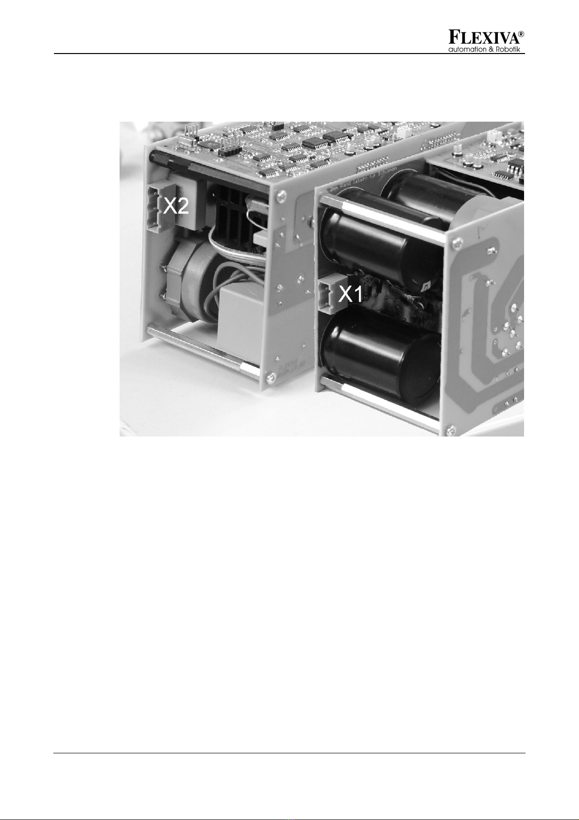
3.3 Power Terminals
Fig. 2: Power terminals
X1: DC link
•Plug with clamp max. 2.5mm²
X2: Output
•Plug with clamp max. 2.5mm²
•+pole, -pole, PE

User Manual DC/DC Module PM3K350
Product Description
Flexiva automation & Robotik GmbH
Weißbacher Straße 3
D – 09439 Amtsberg
13
3.4 Signal Connections
Fig. 3: Signal connections
SV3: Communication interface
The communication with the module is executed by means of an optically isolated
serial interface: To trigger the optocouplers, a supply voltage of 5V (approx. 30mA) is
to be provided. To permit to address several modules in a simple way, the signal RXD
and TXD can be switched-in by means of the SELECT signal. When SELECT is low,
TXD becomes a high-resistance value and RXD does not receive any signals. When
several modules are used, the RXD and TXD lines can be connected in parallel this
way and the currently addressed module can be selected by means of SELECT. All
signals at this interface are on 5V CMOS level that means for the connection with a
PC, a level converter is required such as, for example, represented in the appendix.
Data rate: 115,200bps,
Format: 8bit+1 stop bit
The signals OC_OK and OC_EN are provided for an additional safety feature:
OC_OK gets low, when the DC link voltage has exceeded the upper limit value.
Consequently, a module can inform all the others when this case has occurred by
AND-combining all OC - OK signals and supplying them to OC - EN. This way, it is
possible to prevent major damages when the voltage-measuring amplifier of the DC
link of a module breaks down.

User Manual DC/DC Module PM3K350
Product Description
Flexiva automation & Robotik GmbH
Weißbacher Straße 3
D – 09439 Amtsberg
14
pin abbrevi
ation explanation
1 GND ground
2 VCC +5 V
3 OC_OK H: no overvoltage of the DC link
4 NC not used
5 NC not used
6 SELECT
H: serial interface activated
L: serial interface deactivated
7 OC_EN H: module enabled
8 RXD input of data
9 NC not used
10 TXD output of data
Tab. 1: Pin assignment SV3
SV1 / SV2: Service interfaces
SV1 and SV2 are programming controllers for the microcontrollers of the module.
They are not needed for the operation and are not to be used.

User Manual DC/DC Module PM3K350
Product Description
Flexiva automation & Robotik GmbH
Weißbacher Straße 3
D – 09439 Amtsberg
15
3.5 Safety Information
The DC/DC converter module was developed according to recognized rules of
technology and submitted to a safety test before the delivery.
In case of wrong operations or unauthorized use, there are still dangers for persons
and the DC/DC converter modules.
All persons who erect, operate, or maintain the system must:
1. read and exactly follow the present operating manual,
2. be trained and instructed for their job.
Test voltage between DC link side and communication interface 6kVp
3.5.1 Safety Measures for the Installation
In order to guarantee a troublefree operation and to maintain the service life of the
electronic components, any accumulation of heat, especially at the fronts of the
module is to be avoided. The place of installation is to be selected so that the module
is sufficiently ventilated during the operation.
Attention
The heat sinks are connected with potentials i.e. it is prohibited to touch them!
3.5.2 Remaining Dangers and Risks
The described product is in keeping with the latest technological development and
meets the recognized safety provisions. Nevertheless, dangers and risks may arise.
The remaining dangers and risks occurring in connection with the operation of the
system result from:
•the utilization of electric / electronic components (sources, acceptors, memories) of
third-party suppliers,
•the electricity itself.
For all components built-in, the provisions and safety instructions with regard to the
operation and the place of erection and/or installation applying to each of them are to
be observed and complied with.

User Manual DC/DC Module PM3K350
Product Description
Flexiva automation & Robotik GmbH
Weißbacher Straße 3
D – 09439 Amtsberg
16
3.5.3 Qualification of the Operating Staff
Only such persons are authorized to commission and connect the module who have
an electro-technical special training and who are able to execute the required line
connections expertly.
Basic knowledge of the work on PCs and with the current WINDOWS operating
system is required to use the software supplied along with the modules. Details about
this are contained in the enclosed extensive program description.

User Manual DC/DC Module PM3K350
Preparation of the Product for the Use
Flexiva automation & Robotik GmbH
Weißbacher Straße 3
D – 09439 Amtsberg
17
4 Preparation of the Product for the Use
4.1 Transport
For the transport of the module, attention has to be to the fact that it is not exposed to
any vibrations, heavy shocks as well as jolts and impacts since sensitive components
might be damaged by that.
4.2 Packaging
Basically, packaging is to be used for the transport and/or shipment of the module
that meets the requirements of the destination and the system and is environmentally
acceptable.
Since the module itself has a degree of protection IP00, a transport packing is to be
selected that prevents the penetrating of water, dirt, and dust. The inserting of
conventional desiccating means in the packaging is recommended.
4.3 Storing
Durable storing: closed rooms, dry, room temperature
4.4 Commissioning
Prior to the commissioning, the following conditions are to be assured and to be
checked:
•The expert installation and rating of all necessary electrical connection lines as
well as the correct connection of all components to the module.
•The knowledge of the information and instructions given in the present user's
manual.
4.4.1 Connection of the DC Link
•The cross section of the wires has to be selected according to the current
expected Æ1.5mm² are recommended.
•Take into account the polarity.
4.4.2 Connection of the Output
•The cross section of the wires has to be selected according to the current
expected Æ1.5mm² are recommended.
•Take into account the polarity.

User Manual DC/DC Module PM3K350
Preparation of the Product for the Use
Flexiva automation & Robotik GmbH
Weißbacher Straße 3
D – 09439 Amtsberg
18
4.4.3 Putting into Operation of the Module
1. Read the present documentation!
2. Apply the DC link voltage.
From a voltage of approx. 100V onwards, it is possible to communicate with
the module via RS232.
3. Parameterize it.
4. Switch it on.

User Manual DC/DC Module PM3K350
Operation
Flexiva automation & Robotik GmbH
Weißbacher Straße 3
D – 09439 Amtsberg
19
5 Operation
5.1 Method of Functioning
The DC/DC converter module can transfer power between a DC link with a voltage of
365V...385V and a side with variable voltage in a bidirectional way. Since several
degrees of freedom result from that a more extensive parameterization is required for
that purpose. To reach a maximum flexibility in doing this, the control for the DC link
voltage and the output voltage is digitally realized.
A PIDT1 controller each exists for the DC link and the output. Depending on the mode
of operation, these are linked in a different way. The output value of this linkage is
limited to the corresponding maximum values and is output to the hardware by means
of DAC (vs_isoll). In addition to that, the I-Components of the controllers are also
limited during the limitation so that they do not run up to the maximum values. They
are kept at the limiting value so that are contiguous change from one to the other
controller can be executed.
5.1.1 Modes of Operation
In order to link the output values of the output and DC link voltage regulator, two
possibilities are available.
In the mode of operation 0, the maximum value of the two regulators is used. It is
suited for the operation as an output converter i.e. only load flows out of the module
into a load or for the application of a buffer store, for example of a double-film
capacitor or accumulator. The linkage of the regulators works as follows: If the DC
link voltage is bigger than its set desired value, the output voltage regulator is active
and keeps UVS at a constant level. If the voltage at the DC link drops, the DC link
voltage regulator gains the upper hand and tries to keep the DC link voltage at a
constant level. The following characteristics result from that for this mode of
operation:
•the output voltage is limited upwards and this prevents, for example, an
overcharging of the buffer store,
•the DC link voltage is limited downwards and this prevents a collapse of the DC
link in case of a too big load.
User Manual DC/DC Module PM3K350
Operation
Flexiva automation & Robotik GmbH
Weißbacher Straße 3
D – 09439 Amtsberg
20
Voltages Tendencie
s Input (1) Output (0)
UZK<UZKsoll
UVS<UVSsoll
IsollZ ↑
IsollV ↓
Isoll ↓Isoll ↑
(discharging of the
buffer store)
UZK>UZKsoll
UVS<UVSsoll
IsollZ ↓
IsollV ↓
Isoll ↓Isoll ↓
(
charging of the output
/buffer store)
UZK<UZKsoll
UVS>UVSsoll
IsollZ ↑
IsollV ↑
Isoll ↑
(input e.g. BZ)
Isoll ↑
(energy recovery)
UZK>UZKsoll
UVS>UVSsoll
IsollZ ↓
IsollV ↑
Isoll ↓Isoll ↑
(energy recovery)
Tab. 2: Behavior in the modes of operation
In the mode of operation 1, the minimum value of the two regulators is used as a
current default value. This is favorable for the linking of sources, e.g. of a fuel cell. In
this mode of operation, it is prevented that the output voltage falls below the desired
value and can thus, for example, damage a fuel-cell stack. Consequently, the voltage
regulator of the DC link is usually in operation and keeps the DC link voltage at a
constant level. Only when the output voltage falls below the desired value, the output
voltage regulator gets active and reduces the current so that it is not possible to fall
below the desired value.
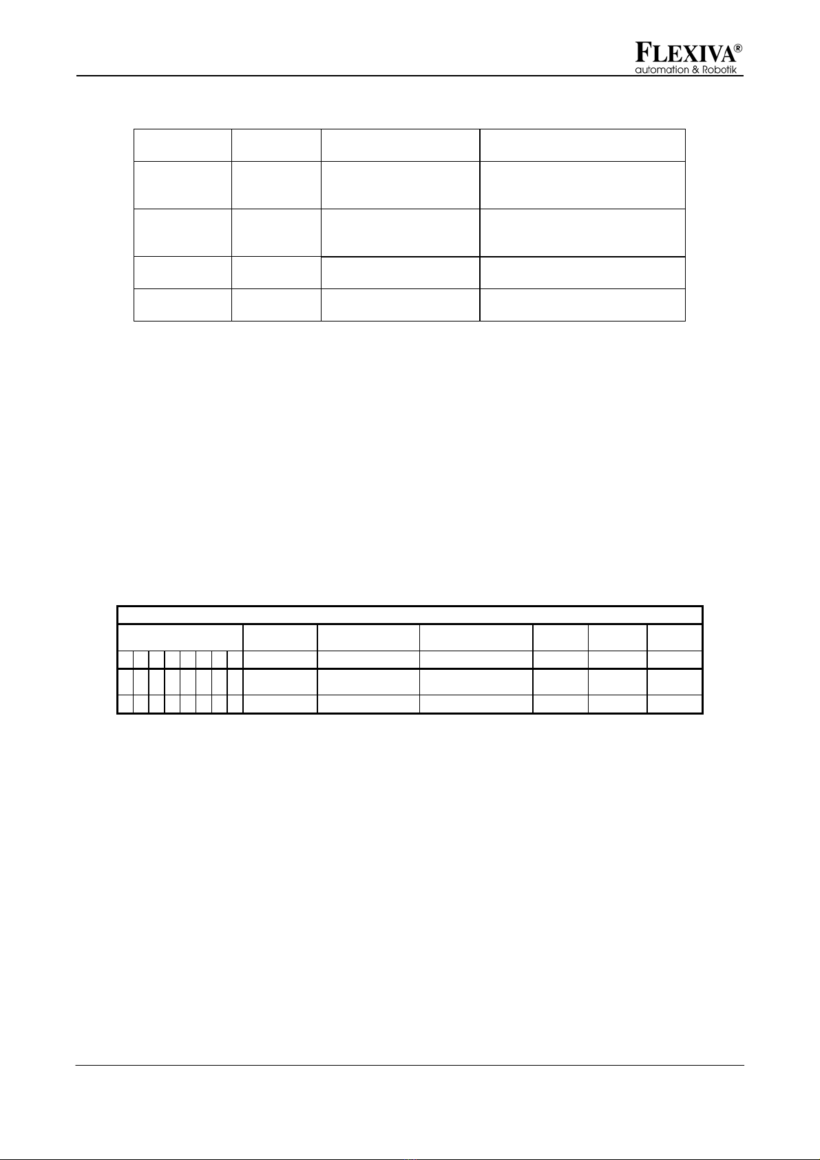
Parameter: mod_opmode
Bit Dec Hex
Mode of
operation Imax Imin UsollVS
7 6 5 4 3 2 1 0
0 0 0 0 0 0 0 0 0 (0x10) 0x00 Output/buffer
store comm comm comm
0 0 0 0 0 0 0 1 1 (0x11) 0x01 Input comm comm comm
Tab. 3: Modes of operation
5.1.2 Parallel Connection of Modules at the Variable Voltage Side
To increase the power, it is to be possible to interconnect several DC/DC converter
modules at the variable voltage side. But this has the following disadvantage: Since
PI controllers are used the output voltage is exactly regulated to meet the desired
value. In case of two DC/DC converters connected in parallel, there are, however,
always little differences in the voltage references so that one DC/DC converter always
accepts the full load until it reaches its current limit. This is unfavorable since the
efficiency of the DC/DC converter is just the highest one in the medium power range.
This problem can be solved by a falling current-voltage characteristic. On principle,
this one already exists through the resistances of the connecting leads, but too low.
Table of contents


