Amperes TD6400 User manual

INSTRUCTION MANUAL
TD6400
2 x 4 Ch Decoder / Zone Selector
VER 2 / 2020
Thank you for choosing another quality product from Amperes Electronics.
TD6400 works similarly to TD6080, but the output zones are divided further to work with 2 x 4 outputs. It provides more
flexibility when it is to work with Matrix Controller ( MxP2288 ) as matrix output zone extender. This shall reduce the number
of unused zones in matrix groupings.
DUAL 4 CH DECODER / ZONE SELECTOR
ZONE 1 ZONE 2 ZONE 3 ZONE 4 ZONE 5 ZONE 6 ZONE 7 ZONE 8
ALL CALL
POWER
amperes
TD 6400

Parts Identification
1
1. LED INDICATORS
POWER LED indicator.
2. ALL CALL SWITCH
3. FRONT PANEL ZONE SWITCH - ZONE 1 - 8
4. DC SUPPLY INPUT
5. MIC INPUT
MIC IN : The connectors are to link to paging mics via EX2800 using 2 pair screen cable or from paging Mic using RJ45
connector.
RS485 : Communication port link to paging mic or external devices.
MIC LINK : Link a paging mic audio signal to the microphone input ( MIC IN ) of the TD6400.
2
4 5 6 8 10
All zones will be activated by pressing this switch, regardless of any inactive zone.
Switching for zone 1 to 8. For grouping of zones using matrix, please refer to page 7.
6. MIXER INPUT ( GROUP A & GROUP B )
PAGE 2 TD6400 | 2 x 4 CH DECODER / ZONE SELECTOR
24V DC supply is required to operate this unit. Ensure polarity is correctly terminated to the port. It is recommended
that supply with 1A rating of regulated source is used. Amperes PS9400 is recommended as a DC supply source to your
installation.
BGM source from mixer output. This shall be used when there is audio (BGM) grouping in the system.
Front View:
Rear View:
DUAL 4 CH DECODER / ZONE SELECTOR
ZONE 1 ZONE 2 ZONE 3 ZONE 4 ZONE 5 ZONE 6 ZONE 7 ZONE 8
ALL CALL
POWER
amperes
TD 6400
-
+
DC 24V
TD 6400
DECODER / SELECTOR
GROUP A
1 2 3 4 5 7 8
ON
6
ON
GROUP B
1 2 3 4 5 7 8
ON
6
ON
MASTER / SLAVE
TIME OUT 5 MIN
S
-
M
0
-
5
1 2
ON
100V
COM
COM
IN 2OUT 1
COM
COM
100V
100V
COM
100V
OUT 2
100V
IN 1
100V
COM
OUT 5
COM
IN 6
100V
100V
IN 5
100V
COM
100V
OUT 4
COM
COM
OUT 6
COM
OUT 3
100V
IN 3
COM
100V
COM
IN 4
100V
COM
100V
OUT 8
COM
OUT 7
100V
IN 7
COM
100V
COM
IN 8
100V
GROUP A GROUP B
+-G
MIC IN
MIC INPUT
G+-
MIC LINK
MIXER INPUT BALANCED OUTPUT
+-G + -
GROUP B
GROUP A
AB
RS485
+-G+-
GROUP B
GROUP A
UNIT START ADDRESS
LINE LEVEL INPUTS / OUTPUTS
RELAY
CONT.
3A NO
MAX
COM
NO
NC
RELAY
TRIG
Another Quality Product From
AMPERES ELECTRONICS
4
8
1
2
64
128
16
32
4
8
1
2
64
128
16
32
3
711
9

Parts Identification ( Con’t )
8. UNIT ADDRESS DIP SWITCHES
Example 1: 1000 0000 - Zone 1 to 4
0110 0000 - Zone 6 to 9
MASTER & SLAVE SETTING
ON = MASTER
OFF = SLAVE
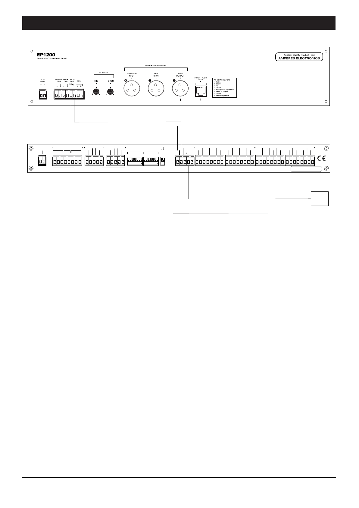
10. EMERGENCY OVERRIDE TERMINAL
11. AMPLIFIER ZONE OUTPUT CONNECTOR ( ZONE 1 - 8 )
TIME OUT SETTING
ON = TIMER 5 MIN
OFF = TIMER INFINITY
TD6400 | 2 x 4 CH DECODER / ZONE SELECTOR PAGE 3
Each TD6400 caters for 2 sets of 4 consecutive zone outputs. Zone assignment is achieved by configure the DIP switch
setting to the binary number of the starting zone. TD6400 allows flexible starting number of each group of zones. Maximum
zone number allowed is 138 ( starting zone must be set to 135 ).
External switch ( eg. from emergency paging mic with dry contact ) can be connected here, which shall trigger the built in
relay when pressed. This shall then provide a dry contact in which would enable the installer to apply several functions
such as providing 24V DC output for volume controller overriding purpose, trigger external device or link to BAS system,
etc. Refer to page 10 for connection diagram.
Outputs from amplifiers are connected to these terminals and speaker zoning is configured to the respective
unit of amplifier. The user has the flexibility to configure the zoning system as each zone comes with single amplifier
output connection. Please observe polarity when terminating the amplifier / speaker zones and ensure that each zone
is not overloaded ( max load 500W l00V line ).
GROUP A
7. BALANCED OUTPUT ( GROUP A & GROUP B )
Balanced audio signal from paging mic and BGM are connected to amplifier audio inputs via these terminals.
When user activate Group A zones via TD6400 front panel switches, the GROUP A - BALANCED OUTPUT will play
BGM, and activation from a paging mic will broadcast paging announcement.
While BGM is playing, activation of paging mic will override the BGM to the group zones and broadcast paging
announcement. Paging signal shall have priority over BGM.
9. DIP SWITCH
DIP setting for Time out, Master and Slave setting
1010 0000 - Zone 5 to 8
1000 0111 - Zone 135 to 138
GROUP B
Note: On DIP switch, ON corresponding to binary 1; OFF corresponding to binary 0.
PIN 1 PIN 2
Example 2:

General Schematic Diagram
PD2400 / 2800
PAGING MIC 1
PD2400 / 2800
PAGING MIC 2
PD2400 / 2800
PAGING MIC 3
EX1103
Cat 5e
2pr screen
POWER AMPLIFIER
QP2000S
SPEAKERS
audio output
(mic / line level)
TD6400
DECODER
POWER
OFF SELECT
TUNER
CD
CASS
OFF
MASTER
MUSIC SOURCE
SIG IN
BASS
MAXMIN
EXT INPUT
MAX MAXMIN
SOURCE
MIN
SIG IN
CHIME MIXER TREBLE
MAXMIN
TONE CTRL
CH5 CH6CH4
SIG INSIGIN SIGIN
MAXMIN MAXMIN MIN
CH3CH1 CH2
SIG INSIG IN
MAXMIN MAXMIN MAXMIN MAX
AUX
SIG IN
amp e re s
M X 2 2 2 2 O
I
MENU
am p e r e s
O
I
POWER
QP2500
UP
DOWN
500W 100V LINE POWER AMPLIFIER
Zone Output
MX2222
PREAMPLIFIER MIXER
audio
output
Amp (100V Line)
O/P
audio & data
------------------
Zone 1 Zone 8
The illustration using multiple paging mic
with TD6400 as zone decoder and zone
selector
Note:
All PD Series of Amperes paging microphones can be used with TD6400.
PAGE 4 TD6400 | 2 x 4 CH DECODER / ZONE SELECTOR
DUAL 4 CH DECODER / ZONE SELECTOR
ZONE 1 ZONE2 ZONE 3 ZONE 4 ZONE 5 ZONE 6 ZONE 7 ZONE 8ALL CALL
POWER
amperes
TD 6400

:
AC 220 - 240V 50/60Hz
Connecting The Unit - Single Unit Installation
For Single unit paging mic, set priority level
to 0 (PD2800) or 00 (PD2400). Priority 1 is
highest.
Rear view of PD2800 Remote location
SPEAKERS
TD6400
MX2222
QP2500
EP1200
- - - - - - - -
Zone 1
100V
- - - - - - - -
TD6400 | 2 x 4 CH DECODER / ZONE SELECTOR PAGE 5
Zone 8
Cat5e
Note:
Also refer to page 10, in using EP1200 to trigger emergency overriding at volume controllers.
100V Output
-
+
DC 24V
TD 6400
DECODER / SELECTOR
GROUP A
1 2 3 4 5 7 8
ON
6
ON
GROUP B
1 2 3 4 5 7 8
ON
6
ON
MASTER / SLAVE
TIME OUT 5 MIN
S
-
M
0
-
5
1 2
ON
100V
COM
COM
IN 2OUT 1
COM
COM
100V
100V
COM
100V
OUT 2
100V
IN 1
100V
COM
OUT 5
COM
IN 6
100V
100V
IN 5
100V
COM
100V
OUT 4
COM
COM
OUT 6
COM
OUT 3
100V
IN 3
COM
100V
COM
IN 4
100V
COM
100V
OUT 8
COM
OUT 7
100V
IN 7
COM
100V
COM
IN 8
100V
GROUP A GROUP B
+-G
MIC IN
MIC INPUT
G+-
MIC LINK
MIXER INPUT BALANCED OUTPUT
+-G + -
GROUP B
GROUP A
AB
RS485
+-G+-
GROUP B
GROUP A
UNIT START ADDRESS
LINE LEVEL INPUTS / OUTPUTS
RELAY
CONT.
3A NO
MAX
COM
NO
NC
RELAY
TRIG
Another Quality Product From
AMPERES ELECTRONICS
4
8
1
2
64
128
16
32
4
8
1
2
64
128
16
32
INPUT
OUTPUT
EX2800
Audio +
Data
IN -
GND
LINKINPUT
IN +
OUT +
OUT -
This illustarated application is used when
a single mic is to be connected to 8 zones
of TD6400.
Link
Audio
Data
24V
2 pair
2 core screen

Connecting The Unit - Multipoint Paging Installations
MIN MAX
AMPERES ELECTRONICS
Quality Product From
MIN MAX
PD2800
Paging Microphone
MIN MAX
AMPERES ELECTRONICS
Quality Product From
MIN MAX
PD2800
Paging Microphone
MIN MAX
AMPERES ELECTRONICS
Quality Product From
MIN MAX
PD2800
Paging Microphone
Cat5e
EX2800
PD2400 / 2800
PD2400 / 2800
PD2400 / 2800
Note :
1) Use EX2800 if more than one PD2400 / 2800 are available in the system. The single from last EX2800 shall
be directly connected to TD6400 mic input port.
2) A higher priority mic shall override any lower priority unit in active.
PD2400 :
3 levels of priority available for PD2400.
PD2800 :
9 levels of priority available for PD2800.
TD6400
INPUT
OUTPUT
For long distance only
Cat5e
24V
2 pair screen cable
18 AWG cable size is recommended
PAGE 6 TD6400 | 2 x 4 CH DECODER / ZONE SELECTOR
-
+
DC 24V
TD 6400
DECODER / SELECTOR
GROUP A
1 2 3 4 5 7 8
ON
6
ON
GROUP B
1 2 3 4 5 7 8
ON
6
ON
MASTER / SLAVE
TIME OUT 5 MIN
S
-
M
0
-
5
1 2
ON
100V
COM
COM
IN 2OUT 1
COM
COM
100V
100V
COM
100V
OUT 2
100V
IN 1
100V
COM
OUT 5
COM
IN 6
100V
100V
IN 5
100V
COM
100V
OUT 4
COM
COM
OUT 6
COM
OUT 3
100V
IN 3
COM
100V
COM
IN 4
100V
COM
100V
OUT 8
COM
OUT 7
100V
IN 7
COM
100V
COM
IN 8
100V
GROUP A GROUP B
+-G
MIC IN
MIC INPUT
G + -
MIC LINK
MIXER INPUT BALANCED OUTPUT
+-G + -
GROUP B
GROUP A
AB
RS485
+-G + -
GROUP B
GROUP A
UNIT START ADDRESS
LINE LEVEL INPUTS / OUTPUTS
RELAY
CONT.
3A NO
MAX
COM
NO
NC
RELAY
TRIG
Another Quality Product From
AMPERES ELECTRONICS
4
8
1
2
64
128
16
32
4
8
1
2
64
128
16
32
Output
INPUT
OUTPUT
EX2800
EX2800
Input Output
24V
24V
INPUT
OUTPUT

Connecting The Unit - BGM Grouping (Matrix)
Music
Music
Matrix
Group 1
Group 8
Paging data & audio
Master
Slave
1
8
57
64
Audio &
Data Link
To power amp. input (Group 1)
From amplifier output
Unit 1 (master)
to zone speaker
(zone 1 & 8)
Output from matrix
(Group 1)
(Group 2)
Unit 2 (slave)
to zone speaker
(zone 9 & 16)
Link
Application Note:
1) This configuration shall be used when grouping of zones is required.
e.g: zone 1 to zone 8 to have same BGM input, Group 1 and so forth.
2) Paging made to a zone in the same group shall mute other zone within the group but would not interrupt zones in
other groups.
3) This setup would normally be used together with matrix controller.
4) Use of DA2208 at paging mic audio output is required if more than 6 amplifiers are installed in the system.
Detailed BGM Grouping
TD6400 | 2 x 4 CH DECODER / ZONE SELECTOR PAGE 7
To power amp. input (Group 2)
-
+
DC 24V
TD 6400
DECODER / SELECTOR
GROUP A
1 2 3 4 5 7 8
ON
6
ON
GROUP B
1 2 3 4 5 7 8
ON
6
ON
MASTER / SLAVE
TIME OUT 5 MIN
S
-
M
0
-
5
1 2
ON
100V
COM
COM
IN 2OUT 1
COM
COM
100V
100V
COM
100V
OUT 2
100V
IN 1
100V
COM
OUT 5
COM
IN 6
100V
100V
IN 5
100V
COM
100V
OUT 4
COM
COM
OUT 6
COM
OUT 3
100V
IN 3
COM
100V
COM
IN 4
100V
COM
100V
OUT 8
COM
OUT 7
100V
IN 7
COM
100V
COM
IN 8
100V
GROUP A GROUP B
+-G
MIC IN
MIC INPUT
G+-
MIC LINK
MIXER INPUT BALANCED OUTPUT
+-G + -
GROUP B
GROUP A
AB
RS485
+-G+-
GROUP B
GROUP A
UNIT START ADDRESS
LINE LEVEL INPUTS / OUTPUTS
RELAY
CONT.
3A NO
MAX
COM
NO
NC
RELAY
TRIG
Another Quality Product From
AMPERES ELECTRONICS
4
8
1
2
64
128
16
32
4
8
1
2
64
128
16
32
-
+
DC 24V
TD 6400
DECODER / SELECTOR
GROUP A
1 2 3 4 5 7 8
ON
6
ON
GROUP B
1 2 3 4 5 7 8
ON
6
ON
MASTER / SLAVE
TIME OUT 5 MIN
S
-
M
0
-
5
1 2
ON
100V
COM
COM
IN 2OUT 1
COM
COM
100V
100V
COM
100V
OUT 2
100V
IN 1
100V
COM
OUT 5
COM
IN 6
100V
100V
IN 5
100V
COM
100V
OUT 4
COM
COM
OUT 6
COM
OUT 3
100V
IN 3
COM
100V
COM
IN 4
100V
COM
100V
OUT 8
COM
OUT 7
100V
IN 7
COM
100V
COM
IN 8
100V
GROUP A GROUP B
+-G
MIC IN
MIC INPUT
G+-
MIC LINK
MIXER INPUT BALANCED OUTPUT
+-G + -
GROUP B
GROUP A
AB
RS485
+-G+-
GROUP B
GROUP A
UNIT START ADDRESS
LINE LEVEL INPUTS / OUPUTS
RELAY
CONT.
3A NO
MAX
COM
NO
NC
RELAY
TRIG
Another Quality Product From
AMPERES ELECTRONICS
4
8
1
2
64
128
16
32
4
8
1
2
64
128
16
32
REMOTE
PAGINGMIC
M P 2288
12 x 8 ETHERNET MATRIX CONTROLLER
x
BALANCED CHANNEL OUTPUTS
BALANCED INPUTS ( XLR - MIC LEVEL / PHONE JACK - LINE LEVEL )
CH 6CH 5CH 4CH 3CH 2CH 1 CH 8CH 7
CH 8CH 7CH 6CH 5CH 4CH 3CH 2CH 1
CASCADEOUT
EP1200
CONNECTION
24VDC IN ; 1 A
+ -
REMOTE
PANEL1
REMOTE
PANEL2
CH4CH1 CH2 CH3
COM
NO
COM
NO
COM
NO
COM
NO
CONFIGURABLEREMOTE TRIGGER
EM/ AC
CONT(NO)
RS485
A B
MATRIXCASCADING TERMINALS
(MAX STACKS : 12 UNITS )
CASCADEIN
ETHERNET
PORT
MESSAGEPLAYER
IN( LINE BAL )
-
+
DC 24V
TD 6400
DECODER / SELECTOR
GROUP A
1 2 3 4 5 7 8
ON
6
ON
GROUP B
1 2 3 4 5 7 8
ON
6
ON
MASTER / SLAVE
TIME OUT 5 MIN
S
-
M
0
-
5
1 2
ON
100V
COM
COM
IN 2OUT 1
COM
COM
100V
100V
COM
100V
OUT 2
100V
IN 1
100V
COM
OUT 5
COM
IN 6
100V
100V
IN 5
100V
COM
100V
OUT 4
COM
COM
OUT 6
COM
OUT 3
100V
IN 3
COM
100V
COM
IN 4
100V
COM
100V
OUT 8
COM
OUT 7
100V
IN 7
COM
100V
COM
IN 8
100V
GROUP A GROUP B
+-G
MIC IN
MIC INPUT
G + -
MIC LINK
MIXER INPUT BALANCED OUTPUT
+-G + -
GROUP B
GROUP A
AB
RS485
+-G + -
GROUP B
GROUP A
UNIT START ADDRESS
LINE LEVEL INPUTS / OUTPUTS
RELAY
CONT.
3A NO
MAX
COM
NO
NC
RELAY
TRIG
Another Quality Product From
AMPERES ELECTRONICS
4
8
1
2
64
128
16
32
4
8
1
2
64
128
16
32
-
+
DC 24V
TD 6400
DECODER / SELECTOR
GROUP A
1 2 3 4 5 7 8
ON
6
ON
GROUP B
1 2 3 4 5 7 8
ON
6
ON
MASTER / SLAVE
TIME OUT 5 MIN
S
-
M
0
-
5
1 2
ON
100V
COM
COM
IN 2OUT 1
COM
COM
100V
100V
COM
100V
OUT 2
100V
IN 1
100V
COM
OUT 5
COM
IN 6
100V
100V
IN 5
100V
COM
100V
OUT 4
COM
COM
OUT 6
COM
OUT 3
100V
IN 3
COM
100V
COM
IN 4
100V
COM
100V
OUT 8
COM
OUT 7
100V
IN 7
COM
100V
COM
IN 8
100V
GROUP A GROUP B
+-G
MIC IN
MIC INPUT
G + -
MIC LINK
MIXER INPUT BALANCED OUTPUT
+-G + -
GROUP B
GROUP A
AB
RS485
+-G + -
GROUP B
GROUP A
UNIT START ADDRESS
LINE LEVEL INPUTS / OUTPUTS
RELAY
CONT.
3A NO
MAX
COM
NO
NC
RELAY
TRIG
Another Quality Product From
AMPERES ELECTRONICS
4
8
1
2
64
128
16
32
4
8
1
2
64
128
16
32
Group 2
Group 7
Data

Connecting The Unit - iPX Paging Client
iPX5151
PAGING CLIENT
TD6400
Network Switch
IN -
GND
LINK
INPUT
IN +
OUT +
OUT -
QP2500
PAGE 8 TD6400 | 2 x 4 CH DECODER / ZONE SELECTOR
PD2800
PD SERIES PAGING MIC
INPUT
OUTPUT
EX2800
}
}
Line Out
24V DC
iPX5155
PAGING CLIENT
100V
SPEAKERS
-
+
DC 24V
TD 6400
DECODER / SELECTOR
GROUP A
1 2 3 4 5 7 8
ON
6
ON
GROUP B
1 2 3 4 5 7 8
ON
6
ON
MASTER / SLAVE
TIME OUT 5 MIN
S
-
M
0
-
5
1 2
ON
100V
COM
COM
IN 2OUT 1
COM
COM
100V
100V
COM
100V
OUT 2
100V
IN 1
100V
COM
OUT 5
COM
IN 6
100V
100V
IN 5
100V
COM
100V
OUT 4
COM
COM
OUT 6
COM
OUT 3
100V
IN 3
COM
100V
COM
IN 4
100V
COM
100V
OUT 8
COM
OUT 7
100V
IN 7
COM
100V
COM
IN 8
100V
GROUP A GROUP B
+-G
MIC IN
MIC INPUT
G+-
MIC LINK
MIXER INPUT BALANCED OUTPUT
+-G + -
GROUP B
GROUP A
AB
RS485
+-G+-
GROUP B
GROUP A
UNIT START ADDRESS
LINE LEVEL INPUTS / OUTPUTS
RELAY
CONT.
3A NO
MAX
COM
NO
NC
RELAY
TRIG
Another Quality Product From
AMPERES ELECTRONICS
4
8
1
2
64
128
16
32
4
8
1
2
64
128
16
32
2 core screen ~ Data + Audio
Cat 5e
This illustarated application is used when
a single mic is to be connected to 8 zones
of TD6400 wire iP paging Client.
Remote location

Cascading The Units
1000 0000
1001 0000
Z 1 ~ Z 8
master
Z 9 ~ Z 16
slave
Z 17 ~ Z 24
slave
The above configurations shows cascading for several TD6400.
Note: That the paging mic audio goes to mixer and thereafter to EP1200. In this case, any paging would mute all incoming BGM.
AMPLIFIER
TD6400 | 2 x 4 CH DECODER / ZONE SELECTOR PAGE 9
Only link
the Data
Only link
the Data
Audio
Data
From paging microphone
-
+
DC 24V
TD 6400
DECODER / SELECTOR
GROUP A
1 2 3 4 5 7 8
ON
6
ON
GROUP B
1 2 3 4 5 7 8
ON
6
ON
MASTER / SLAVE
TIME OUT 5 MIN
S
-
M
0
-
5
1 2
ON
100V
COM
COM
IN 2OUT 1
COM
COM
100V
100V
COM
100V
OUT 2
100V
IN 1
100V
COM
OUT 5
COM
IN 6
100V
100V
IN 5
100V
COM
100V
OUT 4
COM
COM
OUT 6
COM
OUT 3
100V
IN 3
COM
100V
COM
IN 4
100V
COM
100V
OUT 8
COM
OUT 7
100V
IN 7
COM
100V
COM
IN 8
100V
GROUP A GROUP B
+-G
MIC IN
MIC INPUT
G+-
MIC LINK
MIXER INPUT BALANCED OUTPUT
+-G + -
GROUP B
GROUP A
AB
RS485
+-G+-
GROUP B
GROUP A
UNIT START ADDRESS
LINE LEVEL INPUTS / OUTPUTS
RELAY
CONT.
3A NO
MAX
COM
NO
NC
RELAY
TRIG
Another Quality Product From
AMPERES ELECTRONICS
4
8
1
2
64
128
16
32
4
8
1
2
64
128
16
32
-
+
DC 24V
TD 6400
DECODER / SELECTOR
GROUP A
1 2 3 4 5 7 8
ON
6
ON
GROUP B
1 2 3 4 5 7 8
ON
6
ON
MASTER / SLAVE
TIME OUT 5 MIN
S
-
M
0
-
5
1 2
ON
100V
COM
COM
IN 2OUT 1
COM
COM
100V
100V
COM
100V
OUT 2
100V
IN 1
100V
COM
OUT 5
COM
IN 6
100V
100V
IN 5
100V
COM
100V
OUT 4
COM
COM
OUT 6
COM
OUT 3
100V
IN 3
COM
100V
COM
IN 4
100V
COM
100V
OUT 8
COM
OUT 7
100V
IN 7
COM
100V
COM
IN 8
100V
GROUP A GROUP B
+-G
MIC IN
MIC INPUT
G+-
MIC LINK
MIXER INPUT BALANCED OUTPUT
+-G + -
GROUP B
GROUP A
AB
RS485
+-G+-
GROUP B
GROUP A
UNIT START ADDRESS
LINE LEVEL INPUTS / OUPUTS
RELAY
CONT.
3A NO
MAX
COM
NO
NC
RELAY
TRIG
Another Quality Product From
AMPERES ELECTRONICS
4
8
1
2
64
128
16
32
4
8
1
2
64
128
16
32
Note: This is alternative connection from paging mic as compared to diagram in page 5.
1010 0000
Master ON
1011 0000
Slave
1000 1000
1010 1000
Slave

Overriding Volume Controls
- ve
PAGE 10 TD6400 | 2 x 4 CH DECODER / ZONE SELECTOR
24V DC +ve
Note:
Trigger of ‘ALL CALL’ button at TD6400 front panel shall ON all zones but would not be able to override volume controllers.
This is to avoid unnecessary announcement or BGM to be broadcasted to the selected zones.
EP1200 can be used, in case of emergency paging to override the volume controllers by using the above configuration.
-
+
DC 24V
TD 6400
DECODER / SELECTOR
GROUP A
1 2 3 4 5 7 8
ON
6
ON
GROUP B
1 2 3 4 5 7 8
ON
6
ON
MASTER / SLAVE
TIME OUT 5 MIN
S
-
M
0
-
5
1 2
ON
100V
COM
COM
IN 2OUT 1
COM
COM
100V
100V
COM
100V
OUT 2
100V
IN 1
100V
COM
OUT 5
COM
IN 6
100V
100V
IN 5
100V
COM
100V
OUT 4
COM
COM
OUT 6
COM
OUT 3
100V
IN 3
COM
100V
COM
IN 4
100V
COM
100V
OUT 8
COM
OUT 7
100V
IN 7
COM
100V
COM
IN 8
100V
GROUP A GROUP B
+-G
MIC IN
MIC INPUT
G+-
MIC LINK
MIXER INPUT BALANCED OUTPUT
+-G + -
GROUP B
GROUP A
AB
RS485
+-G+-
GROUP B
GROUP A
UNIT START ADDRESS
LINE LEVEL INPUTS / OUTPUTS
RELAY
CONT.
3A NO
MAX
COM
NO
NC
RELAY
TRIG
Another Quality Product From
AMPERES ELECTRONICS
4
8
1
2
64
128
16
32
4
8
1
2
64
128
16
32

Technical Data
TD6400 | 2 x 4 CH DECODER / ZONE SELECTOR PAGE 11
Note:
The above specifications are correct at time of printing but subjected to changes without prior notice due to product
improvements.
Operating voltage
Consumption
Max load / channels
Cascade quantity
Configuration
Input circuits
Audio Output
Number of zones
Amplifier inputs
Zone selection
Indicators
Switch mode
AUDIO
Input impedance (Ohm)
Output impedance
Freq response
Audio input
Max audio output
DATA
Data protocol
Baud rate
Dimension (W x H x D)
Weight
24V DC
6W (250 mA)
500W at 100V line
8
8
Front panel switch & remote
Individual zone switch
Individual, All Call Local zone selection
bypassed when remote trigger is actived
Line : 10 K
600 Ohm balanced
70 ~ 15 KHz
Line
Line 1.2V
RS485
19.2 kbps
482 x 44 x 180 mm
2.00 kg
31 ( 248 zone )
2 in x 4 zones
3 : 1 mic, 2 BGM
2

Warranty Conditions
Disclaimer
ISO 9001: 2015
Design & Manufacture of Public Address Equipment and Systems
AMPERES ELECTRONICS SDN BHD
MADE IN MALAYSIA
Published : June 2020
Only Amperes Electronics Service Centres are allowed to make warranty repairs : a list of Amperes Electronics
Service Centres may be asked for by the purchaser or send directly to Amperes Electronics Sdn Bhd at 70 Jalan
Industri PBP 3, Tmn Perindustrian Pusat Bandar Puchong, 47100, Puchong, Selangor, Malaysia or its authorized
dealers. This warranty is not valid if repairs are performed by unauthorized personnel or service centres.
This warranty covers only repairs and replacement of defective parts ; cost and risks of transportation as well as
removal and installation of the product from the main system are for the account of the purchaser. This warranty
shall not extend to the replacement of the unit.
This warranty does not cover damages caused by misuse, neglect, accident of the product as well as using the
product with power supply voltage other than shown on the product, or any other power supply source / adaptor
not recommended by the manufacturer.
This warranty does not cover damages caused by fire, earthquakes, floods, lightning and every cause not directly
related to the unit.
This warranty does not include any indemnity in favor of the purchaser or the dealer for the period out of use of the
unit; moreover the warranty does not cover any damages which may be caused to people and things when using
the product.
This warranty certificate is valid only for the described product, and is not valid if modifications are made on this
certificate or on the identification label applied on the product.
This warranty covers all the material and manufacturing defects and is valid for a period of 36 months from the
date of purchase or for a specified period in countries where this is stated by a national law. In this case, the
extension is valid only in the country where the product is purchased.
Amperes Electronics Sdn Bhd is not obliged to modify previously manufactured products under warranty if the
design changes or improvements are made.
Information contained in this manual is subject to change without prior notice and does not represent a
commitment on the part of the vendor. AMPERES ELECTRONICS SDN BHD shall not be liable for any loss or
damages whatsoever arising from the use of information or any error contained in this manual.
It is recommended that all services and repairs on this product be carried out by AMPERES ELECTRONICS SDN
BHD or its authorized service agents.
AMPERES series must only be used for the purpose they were intended by the manufacturer and in conjunction
with this operating manual.
AMPERES ELECTRONICS SDN BHD cannot accept any liability whatsoever for any loss or damages caused by
service, maintenance or repair by unauthorized personnel, or by use other than that intended by the manufacturer.
Table of contents
Other Amperes Media Converter manuals
Popular Media Converter manuals by other brands

Speaka Professional
Speaka Professional 2618627 operating instructions

Inline
Inline 76670I user manual

Crestron
Crestron DM NVX 4K60 product manual

Colorado Video
Colorado Video 641 series instruction manual

HIK VISION
HIK VISION DS-6300DI-T user manual

DEVA Broadcast
DEVA Broadcast DB90-TX Setup instructions

Xtreme Power
Xtreme Power 65067 Owner's manual and safety instructions

HEIDENHAIN
HEIDENHAIN LIF 171R Mounting instructions

LEAB
LEAB PP 48-12/29 Assembly instructions

EuroLite
EuroLite VSD Series user manual

J-Tech Digital
J-Tech Digital JTD-164 user manual

Elsner
Elsner GPS-DCF Converter UTC± Technical specifications and installation instructions