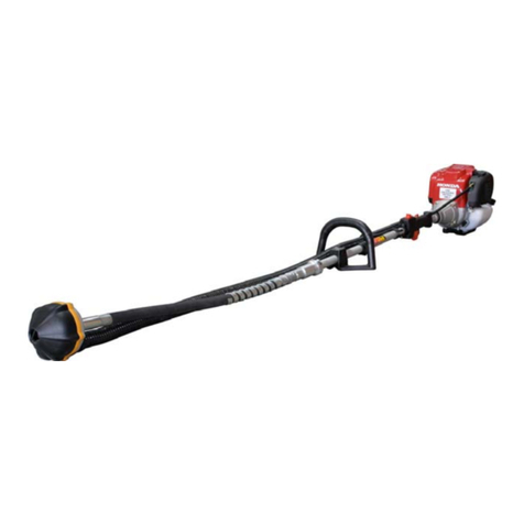
Flextool FP212G User manual

FOR MORE INFORMATION
CONTACT US ON 1300 353 986 OR VISIT flextool.com.au
Version 2.0 (October 2022)
OPERATING INSTRUCTIONS
FLEXTOOL SUBMERSIBLE PUMPS
FP212G, FP212A, FP212C

FLEXTOOL OPERATING INSTRUCTIONS FLEXTOOL SUBMERSIBLE PUMPS
2
1300 353 986 flextool.com.au
FLEXTOOL OPERATING INSTRUCTIONS SUBMERSIBLE PUMPS
2
1300 353 986 flextool.com.au
2
CONTENTS
Introduction 2
Applications 2
Functions and controls 2
Accessories 2
Hazards and risks 2-3
Operation 3
Care and preventive maintenance 4
Cleaning and storage 4
Specifications 4
Service 4
Dismantling 5
Assembling 5
Trouble shooting 6
Spare parts and service 6
INTRODUCTION
APPLICATIONS
Dams, mines, tanks, tankers, swimming pools, pits, trenches,
excavations, construction sites, canal dredging, pile sinking.
Harbour & rescue services, pork producers, abbotoirs,
plumbers, drainers, builders, rural producers, government,
water, sewerage, power & telecommunication authorities.
Industrial plants, maintenance workshops, hire contractors.
The pump is suitable for continuous use at temperatures up to
65oC.
Operation at higher temperatures up to 95oC is permissible
providing immersion is intermittent and is not continuous.
Thank you for your selection of Flextool equipment.
Flextool have specialised in the design and manufacture of quality
products since 1951.
We have taken care in the design, manufacture and testing of this
product. Should service or spare parts be required, prompt and
efficient service is available from our extensive dealer network.
General safety instructions for the operation of power equipment
The goal of Flextool is to produce power equipment that helps the
operator work safely and efficiently. The most important safety device
for this or any tool is the operator. Care and good judgement are the
best protection against injury. All possible hazards cannot be covered
here, but we have tried to highlight some of the important items,
individuals should look for and obey Caution, Warning and Danger
signs placed on equipment, and displayed in the workplace.
Operators should read and follow safety instructions packed with
each product. Learn how each machine works. Even if you have
previously used similar machines, carefully check out each machine
before you use it. Get the “feel” of it and know its capabilities,
limitations, potential hazards, how it operates, and how it stops.
torque from the drive unit to the pump head. Submersible operation
of the pump head ensures that it is self priming and does not
require suction hose.
The pump is designed with wide passages through the strainer,
impeller and body to allow the unobstructed passage of solids. It is
suitable for handling fluids with a high solid content such as sand,
sludge, silt, effluent up to 60% in suspension, oil and water.
The pump is available with general purpose, abrasive resistant
and chemical resistant pump head models. The pump should
be selected with a model that best suits the most common
applications.
Select the shortest standard flexshaft length (6 or 9 m) to suit the
common application/s.
The pump is fitted with a quick action 60 mm (2.36 in) diameter
flexible shaft coupling for operation from a drive unit fitted with a 45
mm (1.75 in) diameter 3-tooth dog drive.
ACCESSORIES
Drive units are available with petrol and diesel motor drives.
Extension flexshafts (6 m) extend the length of an existing pump
flexshaft and are available to enable dewatering of holes to a
depth of 12 metre. A sealed quick-action coupling allows
underwater operation of the coupling.
HAZARDS AND RISKS
NEVER allow any person to operate a machine without adequate
instruction.
ENSURE all operators read, understand and follow the operating
instructions.
SERIOUS INJURY may result from improper or careless use of this
machine. Some models of P212 pumps weigh in excess of 25 kg.
Handling and positioning may require two people of appropriate
strength, along with correct lifting techniques
! MECHANICAL HAZARDS
DO NOT operate the pump with the body removed.
KEEP hands and feet clear of rotating and moving parts as they will
cause injury if contacted.
DO NOT leave the equipment in operation while it is unattended.
ENSURE that the equipment will remain stable and will not move or
fall while in operation.
DO NOT operate the pump without a discharge hose fitted.
ENSURE that the pump hose is securely fastened to the pump
outlet via an appropriately sized coupling and adaptor.
ENSURE that repairs to machinery are carried out by COMPETENT
personnel.
FUNCTIONS AND CONTROLS
The product is a submersible pump. The pump head operates
underwater, driven by a rotating flexible shaft that transmits the

FLEXTOOL OPERATING INSTRUCTIONS FLEXTOOL SUBMERSIBLE PUMPS
3
1300 353 986 flextool.com.au
FLEXTOOL OPERATING INSTRUCTIONS SUBMERSIBLE PUMPS
3
1300 353 986 flextool.com.au
3
! FIRE & EXPLOSION HAZARDS
PETROL is extremely flammable and explosive under certain
conditions.
! CHEMICAL HAZARDS
CARBON MONOXIDE exhaust gases from internal combustion
motor driven units can cause death in confined spaces.
! ADDITIONAL HAZARDS
HANDLE IMPELLERS WITH CARE when the pump body is
removed. Pumps that have been subject to extensive use with
abrasive materials may have impellers that are severely worn leaving
sharp, thin or brittle sections.
USE GLOVES when handling and inspecting the flexible shaft outer
casing. Excessive wear of the rubber cover can expose the wire
braided reinforcement, allowing it to project and cause injury.
DO NOT use the pump for handling flammable liquids.
Slip/Trip/Fall is a major cause of serious injury or death.
Beware of excess hose, the flexible shaft and water left on the
walking or work surface.
DO NOT allow waste water to accumulate under foot.
EXERCISE care when working in the vicinity of unprotected holes or
excacations.
Sump pumping is the simplest method of dewatering.
Pumping from ‘open’ sumps is generally used in coarse sands and
gravels. It is difficult to control the migration of ‘fines’ and should
not be used if soil displacement is a critical factor of consideration
when working near existing structures, roads, etc.
ADDITIONAL INFORMATION
Refer to the drive unit operation instructions for additional safety
and operation information on the appropriate drive unit.
OPERATION
For information on correct starting procedures refer to the engine
manufacturers operation manual.
Do not engage the drive coupling while the motor is rotating.
Before engaging the flexshaft with a petrol drive unit start the motor
using the recoil starter, increase the speed to full throttle and allow
it to warm up for a few minutes.
Stop the motor.
Turn the bell housing trigger 180 degrees. Insert the flexshaft
coupling fully into the housing of the drive unit and release the
trigger. Push the coupling into the housing and twist the flexible
shaft until the drive dogs are fully engaged and the trigger returns to
the horizontal position.
The motor may now be started.
If the pump flexible shaft is fitted with an external movable spring,
it should be positioned to provide support where the shaft passes
over the edge of a trench or obstruction.
When pumping from deep pits or excavations avoid subjecting the
flexshaft to the total weight of the pump and the discharge hose.
Support the weight of the pump by attaching a rope to one of the
pump eye-nuts. Secure the other end of the rope to a support
adjacent to the power unit so that it takes the weight of the pump
off the flexshaft.
Drive units should be operated on a level surface. If the surface is
not level the drive unit should be restrained to ensure that it does
not move due to vibration or the weight of the pump and the hose.
Avoid extended running of the pump without water, or with the
flexible shaft in a tight curve.
Never operate the pump flexible shaft in the reverse direction, as
this will damage the flexible core. If the impeller is fouled, remove
the bearing housing and manually clear the impeller.
HOW TO GET THE BEST PERFORMANCE FROM YOUR
PUMP.
Maximum discharge performance of the pump will only be
obtained when a reinforced discharge hose is used. This minimises
kinking where the hose passes over obstructions and permits the
unobstructed passage of solids.
If there is a tendency for the pump head to bury itself in heavy
sediment, overcome this by improvising an auxiliary strainer.
Remove the top from an empty 20 litre drum and punch openings
around the sides. Place the pump head in the drum below the
water.
Improved head performance will be obtained by increasing the
governed speed of the drive unit motor. It is recommended that
a motor with a minimum output of 5.6 kW (7.5 hp) is used for
continuous running above 3,000 r/min.
PUMPING CLEAN WATER
When there is a need to pump clean water without the sludge, grit
or solids that have collected at the bottom of a stream, dam, tank
or pit, keep the pump off the bottom. This will also minimise wear
from pumping abrasive materials.
In a pit or excavation attach a rope to an eye nut on the pump and
suspend the pump from the rope.
In dams and ponds support the pump from a float made from an
empty sealed steel or plastic container or a marine buoy.
PUMPING HEAVY SLUDGE AND SOLIDS
Best results are obtained if the solids on the bottom of the pit or
pond are stirred into the surface liquid. The most effective way
of achieving this is to direct a hose from the submersible pump,
a large volume tap or a second pump, using waste water, into
the tank or pit for a short time until the solids are stirred from the
bottom.
USE A SUITABLE HOSE
Layflat hose is lightweight and rolls flat to facilitate handling and
storage, lt is less expensive than reinforced discharge hose.
However, layflat hose can kink and impede the flow of the fluid
and solids. For best results when using layflat hose, lay it flat on
the ground keeping it free from kinks, bends and twisting where
possible.
A reinforced hose of 50 mm diameter will improve the discharge
performance, while a 75 mm diameter hose will give superior
discharge performance.
QUICK ACTION HOSE FITTINGS
Cam lever-action fittings enable quick connection of hose to the
pump. They save time and eliminate problems with dirty screw
threads and missing washers that are common with nut and tail
screw thread fittings. Joiners are available for coupling separate
hoses.

FLEXTOOL OPERATING INSTRUCTIONS FLEXTOOL SUBMERSIBLE PUMPS
4
1300 353 986 flextool.com.au
FLEXTOOL OPERATING INSTRUCTIONS SUBMERSIBLE PUMPS
4
1300 353 986 flextool.com.au
4
CARE AND PREVENTIVE MAINTENANCE
The most critical part of the pump is the seal. This is because the
seal is subject to wear, particularly when the pump is handling
abrasive materials. It is important that the seals and the sleeve are
replaced before they have worn excessively. If the seals and sleeve
are allowed to wear until failure occurs water will enter the spindle
bearings.
Noisy bearings will not be apparent due to the noise level from the
drive motor.
If the pump is operated unchecked in this condition water will
eventually enter the flexshaft. Naturally, the cost of repairing, a
pump which has been allowed to deteriorate in this way will be
greater.
Regular inspection of the pump and the seal will avoid these
problems.
Check the 3-tooth dog on the drive coupling to ensure that it is fully
meshed and not worn.
Check the strainer for missing sections that could allow the entry of
large objects and result in damage or obstruct ion of the impeller or
volute.
Dismantle the pump and the flexible shaft every 500 hours.
Inspect for wear and lubricate before reassembling
Apply a liberal quantity of grease to the core assembly when
inserting it into the casing assembly from the drive coupling end.
If the spindle is worn by the seal/s located in the adaptor and it is
otherwise satisfactory for further use do not remove the existing
worn seal/s from the screwed adaptor. The bore of the adaptor is
deep enough to accommodate additional seal/s which will then be
located on an unworn area of the spindle.
Check the flexible shaft for kinks and external damage by laying it
out straight on a workbench or the floor. Although it still operates a
badly kinked flexible shaft may result in a broken inner core.
CLEANING AND STORAGE
It is advisable to operate the pump in clean water after use each
day or before storing when it has been used in sludge or water with
a high solid content. This will ensure that mud and sludge do not
dry out and obstruct the body or the impeller.
The three eye nuts can be unscrewed to allow removal of the pump
body and access to the impeller.
Hire operators should check the impeller for rags, solidified mud
and debris after each hire. While the body is removed check the
spindle bearings for slackness and smooth rotation.
SPECIFICATIONS
General Purpose Model P212G
@ 2,900 r/min
Maximum head 16.5 m
Maximum discharge 63,000 litre/h
@3,700 r/min
Maximum head >26.0 m
Maximum discharge >64,500 litre/h
ABRASION RESISTANT MODEL P212A
CHEMICAL RESISTANT MODEL P212C
@ 2,900 r/min
Maximum head 15.0 m
Maximum discharge 56,400 litre/h
@3,700 r/min
Maximum head 26.0 m
Maximum discharge 64,500 litre/h
Outlet 50 mm (2 in BSP)
Solids Up to 28 mm dia. or up
to 60% in suspension
Flexshaft dia (mm) Std 13 x 32
HD 16 x 38
SERVICE
! CAUTION
Read the operating instructions before servicing this product
and note the safety information.
Exercise care when handling flexible shaft casings. Severe wear
or damage to the rubber cover may allow the internal wire braid
to protrude and cause injury.
Exercise care when handling pump impellers. Extreme wear may
result in thin sections or sharp surfaces and cause injury.
4
Inspect for wear and lubricate before reassembling
Apply a liberal quantity of grease to the core assembly when
inserting it into the casing assembly from the drive coupling end.
If the spindle is worn by the seal/s located in the adaptor and it is
otherwise satisfactory for further use do not remove the existing
worn seal/s from the screwed adaptor. The bore of the adaptor is
deep enough to accommodate additional seal/s which will then be
located on an unworn area of the spindle.
Check the flexible shaft for kinks and external damage by laying it
out straight on a workbench or the floor. Although it still operates a
badly kinked flexible shaft may result in a broken inner core.
CLEANING AND STORAGE
It is advisable to operate the pump in clean water after use each
day or before storing when it has been used in sludge or water with
a high solid content. This will ensure that mud and sludge do not
dry out and obstruct the body or the impeller.
The three eye nuts can be unscrewed to allow removal of the pump
body and access to the impeller.
Hire operators should check the impeller for rags, solidified mud
and debris after each hire. While the body is removed check the
spindle bearings for slackness and smooth rotation.
to 60% in suspension
Flexshaft dia (mm) Std 13 x 32
HD 16 x 38
SERVICE
! CAUTION
Read the operating instructions before servicing this product
and note the safety information.
Exercise care when handling flexible shaft casings. Severe wear
or damage to the rubber cover may allow the internal wire braid
to protrude and cause injury.
Exercise care when handling pump impellers. Extreme wear may
result in thin sections or sharp surfaces and cause injury.

FLEXTOOL OPERATING INSTRUCTIONS FLEXTOOL SUBMERSIBLE PUMPS
5
1300 353 986 flextool.com.au
FLEXTOOL OPERATING INSTRUCTIONS SUBMERSIBLE PUMPS
5
1300 353 986 flextool.com.au5
DISMANTLING
TO REMOVE THE PUMP FROM THE FLEXIBLE SHAFT
Remove the pump body from the housing by unscrewing the
eyenuts.
Unscrew the casing from the adaptor with spanners on the
adaptor spanner flats and ferrule.
Pull the ferrule away from the adaptor to expose the spindle
and the core end.
TO REMOVE THE COUPLING FROM THE FLEXIBLE SHAFT
Unscrew the casing from the coupling using spanners on the
housing spanner flats and ferrule.
Pull the ferrule away from the housing to expose the spindle
and the core end.
TO REMOVE THE CORE FROM THE CASING
Lay the flexible shaft out straight on a long workbench or the
floor.
Pull the core out by hand ,coil it and lay it on down on clean
newspaper.
Inspect
Casing for kinks, wear and damage.
Core for wear and kinks.
TO DISMANTLE THE PUMP
Unscrew the impeller from the spindle with a lever through
blades and a spanner on the spindle spanner flats.
Hold the housing in a vice.
Unscrew the adaptor from the housing using a spanner on the
spanner flats.
Drain the oil from the housing and support it with the flange
uppermost.
Press the spindle, bearings and spacer out of the housing.
Press the spindle out of the bearings after removing the circlip
Support the housing with the flange down and press the seals
out off the housing.
Support the adaptor with the largest thread down and press
the seals out off the adaptor.
Slide the sleeve off the spindle over the external thread and
remove the o-ring.
Remove the o-rings from the adaptor.
INSPECT
Pump body and plate for wear.
Impeller for wear.
Housing and plate for wear and corrosion
Housing seals and seal sleeve for wear.
Adaptor seals and spindle seal diameter for wear.
Bearings for wear.
Strainer for missing grille segments.
Note: Because the pump seals are subject to wear, particularly
when the pump is handling abrasive materials, it is important
that the seals and sleeve are replaced before they have worn
excessively. If the seals and sleeve are allowed to wear until seal
failure occurs allow water will enter the spindle bearings.
If the pump is operated unchecked in this condition water will
eventually enter the flexshaft. Regular inspection of the pump and
the seal will avoid these problems.
To dismantle the coupling
Unscrew the socket set screw from the housing.
Support the housing with the thread uppermost.
Press the spindle, seal, bearings and space out of the housing.
Support the spindle on the seal with the threaded end
uppermost and press the spindle out of the bearings after
removing the circlip.
Remove the o-ring from the housing.
INSPECT
Spindle dog teeth for wear.
Spindle dog seal diameter and seal for wear.
Bearings for wear.
ASSEMBLING
Clean the pump and coupling parts by washing in safety
solvent.
Clean the core assembly by wiping it with a clean cloth.
Reverse the above assembly procedure.
Ensure that the seals are correctly assembled with the housing
seal lips and the adaptor seal lips facing out when pressed into
position.
Fit the coupling to the same end of the casing that the core
was inserted through.
LUBRICATION
Pump
Apply a grease film to o-rings, seal lips, seal sleev e and spindle
seal diameter.
Fill the housing with oil to cover bearing before screwing the
adaptor into the housing.
Coupling
Pack the bearings and the spacer with grease.
Apply a grease film to the o-ring, the seal lips and the dog seal
diameter.
FLEXSHAFT
Apply a liberal coating of grease to the core as it is inserted into
the casing.

FLEXTOOL OPERATING INSTRUCTIONS FLEXTOOL SUBMERSIBLE PUMPS
6
1300 353 986 flextool.com.au
FLEXTOOL OPERATING INSTRUCTIONS SUBMERSIBLE PUMPS
6
1300 353986flextool.com.au
TROUBLESHOOTING
SYMPTOM POSSIBLE CAUSES AND CORRECTION
The drive motor is
operating but the pump
is not functioning.
Check that the coupling is fully inserted in the bell housing and secured by the trigger.
Check that the impeller is not obstructed.
Check that a kink in the discharge hose has not created an air lock preventing water from initially
entering the pump.
Check that the pump is sufficiently submerged to allow water to cover the impeller.
Check that electric motor rotation is as shown by the direction arrow on the bell housing (anti-clockwise
when viewing its drive dog).
Check that the threaded core ends on the flexible drive core have not unscrewed from the pump or
coupling spindle due to reverse rotation of the motor.
Check that the inner flexible core has not failed.
There is a tendency
for the pump head to
bury itself in the heavy
sediment
Overcome this by improvising an auxiliary strainer. Remove the top from an empty 20 litre drum and
punch openings around the sides. Place the pump head in the drum below the water.
Model
Flexshaft
Length
m (ft)
Operating
Weight
kg (lb)
Shaft
Core Diameter
mm (in)
Shaft Casing
Diameter
mm (in)
Discharge
Diameter
mm (in)
Max
Discharge Head
m (ft)
Max
Discharge
l/h (gal/h)
Solids
Capacity
mm (in)
Product Code
Australia
FP212G-6 6
(19.7)
26.5
(58.4)
13
(0.5)
32
(1.3)
50
(2)
26
(85.3)
63,000
(16,642)
28
(1.1) FT201801-UNIT
FP212G-9 9
(29.5)
38
(83.8)
13
(0.5)
32
(1.3)
50
(2)
26
(85.3)
63,000
(16,642)
28
(1.1) FT201803-UNIT
Model
Flexshaft
Length
m (ft)
Operating
Weight
kg (lb)
Shaft
Core Diameter
mm (in)
Shaft Casing
Diameter
mm (in)
Discharge
Diameter
mm (in)
Max
Discharge Head
m (ft)
Max
Discharge
l/h (gal/h)
Solids
Capacity
mm (in)
Product Code
Australia
FP212A-6 6
(19.7)
34
(75)
15
(0.6)
38
(1.5)
50
(2)
26
(85.3)
63,000
(16,642)
28
(1.1) FT201805-UNIT
FP212A-9 9
(29.5)
42.5
(93.7)
15
(0.6)
38
(1.5)
50
(2)
26
(85.3)
63,000
(16,642)
28
(1.1) FT201818-UNIT
GENERAL PURPOSE PUMPS
ABRASION RESISTANT PUMPS
Model
Flexshaft
Length
m (ft)
Operating
Weight
kg (lb)
Shaft
Core Diameter
mm (in)
Shaft Casing
Diameter
mm (in)
Discharge
Diameter
mm (in)
Max
Discharge Head
m (ft)
Max
Discharge
l/h (gal/h)
Solids
Capacity
mm (in)
Product Code
Australia
FP212C-6 6
(19.7)
37.5
(82.7)
15
(0.6)
38
(1.5)
50
(2)
26
(85.3)
63,000
(16,642)
28
(1.1) FT201817-UNIT
CHEMICAL RESISTANT PUMPS*
*Improved chemical resistance to a wide range of chemicals compared to general purpose pumps.

Parchem Construction Supplies Pty Ltd
1956 Dandenong Road, Clayton VIC 3168, Australia
Phone: 1300 353 986
flextool.com.au
ABN 80 069 961 968
This manual summarises our best knowledge of the product based on the information available at the time of publication. You should read this manual carefully and
consider the information in the context of how the product will be used. Our responsibility for products sold is subject to our standard terms and conditions of sale.
DISCLAIMER:
Any advice, recommendation, information, assistance or service provided by us in this manual is given in good faith and is believed by us to be appropriate and reliable.
However, any advice, recommendation, information, assistance or service provided by us is provided without liability or responsibility PROVIDED THAT the foregoing shall
not exclude, limit, restrict or modify the right entitlements and remedies conferred upon any person or the liabilities imposed upon us by any condition or warranty implied
by Commonwealth, State or Territory Act or ordinance void or prohibiting such exclusion limitation or modification. The product can be expected to perform as indicated
in this manual so long as operation and operational procedures of the individual products are followed as recommended in this manual.
Design and technical specifications may be subject to changes.
© This publication is copyright. All rights are reserved. Flextool is a registered trade mark of Parchem Construction Supplies Pty Ltd.
FOR MORE INFORMATION
CONTACT US ON 1300 353 986 OR VISIT flextool.com.au
This manual suits for next models
7
Table of contents
Other Flextool Water Pump manuals