manuals.online logo
Brands
  1. Home
  2. •
  3. Brands
  4. •
  5. Sunfab
  6. •
  7. Water Pump
  8. •
  9. Sunfab SVH Series User manual

Sunfab SVH Series User manual

This manual suits for next models

4

Other Sunfab Water Pump manuals

Sunfab SLPD20/20-64/32DIN User manual

Sunfab

Sunfab SLPD20/20-64/32DIN User manual

Sunfab SCPD 70/36 DIN BY-PASS User manual

Sunfab

Sunfab SCPD 70/36 DIN BY-PASS User manual

Sunfab SCPD 76 User manual

Sunfab

Sunfab SCPD 76 User manual

Sunfab SCPD 56/26 DIN User manual

Sunfab

Sunfab SCPD 56/26 DIN User manual

Sunfab SCPD 76 User manual

Sunfab

Sunfab SCPD 76 User manual

Popular Water Pump manuals by other brands

Watershed Innovations HYDRAPUMP SMART FLEX Instructional manual

Watershed Innovations

Watershed Innovations HYDRAPUMP SMART FLEX Instructional manual

Graco Modu-Flo AL-5M instructions

Graco

Graco Modu-Flo AL-5M instructions

Messner MultiSystem MPF 3000 operating instructions

Messner

Messner MultiSystem MPF 3000 operating instructions

Xylem Bell & Gossett WEHT0311M Installation, operation and maintenance instructions

Xylem

Xylem Bell & Gossett WEHT0311M Installation, operation and maintenance instructions

WilTec 50739 Operation manual

WilTec

WilTec 50739 Operation manual

Franklin Electric Little Giant 555702 HRK-360S instruction sheet

Franklin Electric

Franklin Electric Little Giant 555702 HRK-360S instruction sheet

Ingersoll-Rand PD02P Series Operator's manual

Ingersoll-Rand

Ingersoll-Rand PD02P Series Operator's manual

VS ZJ Series Operating	 instruction

VS

VS ZJ Series Operating instruction

Flotec FPZS50RP owner's manual

Flotec

Flotec FPZS50RP owner's manual

SKF Lincoln FlowMaster II User and maintenance instructions

SKF

SKF Lincoln FlowMaster II User and maintenance instructions

Xylem Lowara LSB Series Installation, operation and maintenance instructions

Xylem

Xylem Lowara LSB Series Installation, operation and maintenance instructions

Water Duro Pumps DCJ500 Operating & installation instructions

Water

Water Duro Pumps DCJ500 Operating & installation instructions

Action P490 Operating instructions & parts manual

Action

Action P490 Operating instructions & parts manual

Flo King Permacore Reusable Carbon Bag Disassembly. & Cleaning Instructions

Flo King

Flo King Permacore Reusable Carbon Bag Disassembly. & Cleaning Instructions

ARO ARO PD15P-X Operator's manual

ARO

ARO ARO PD15P-X Operator's manual

Pumptec 112V Series Operating instructions and parts manual

Pumptec

Pumptec 112V Series Operating instructions and parts manual

Virax 262070 user manual

Virax

Virax 262070 user manual

Neptun NPHW 5500 operating instructions

Neptun

Neptun NPHW 5500 operating instructions

manuals.online logo
manuals.online logoBrands
  • About & Mission
  • Contact us
  • Privacy Policy
  • Terms and Conditions

Copyright 2025 Manuals.Online. All Rights Reserved.

Sunfab Hydraulics AB, Box 1094, SE-824 12 Hudiksvall, Sweden. Tel: +46 650-367 00, Fax: +46 650-367 27, E-mail: sunfab@sunfab.se Web: www.sunfab.com
1
(1)
(2)
(3)
(4)
(5)
Pump and tank
Pump SVH can be ordered in left or right-hand versions depending on the
direction of rotation of the power take off.
The tank must be equipped with oil pipes (1) around the return filter for
optimal de-aeration of the oil. The size of the oil filter (2) must correspond to
4 x the effective pump flow with a degree of purification of 10 μm absolute.
Should the system require cooling for optimal efficiency, a cooler must be
placed on the return line or in a separate circuit. The amount of oil in the tank
should correspond to the maximum pump flow during 2 minutes. A breather
filter (3) of 10μm must be installed so that moisture and contaminants cannot
enter the tank. The air flow at 0.1 bar pressure difference should at least be
equal to the maximum oil flow.
The tank should be positioned close to the pump on a level so that the lowest
oil level does not come below the pump level. Pipes are routed so that air
pockets cannot form to prevent cavitation and noise. Any suction shut-off
valve (4) must have an internal diameter that is not less than the suction line.
There must be a pressure relief valve (5) in the system. It must be installed
close to the pump if there are long pipes to the operating valve.
Pipe dimensions, inside mm (di)
Max pump flow l/m 90 120 160 220
Suction-pipe ¹) 50 50 63 75
Return line 32 32 38 45
Pressure line 19 25 25 32
¹) If the suction pipe is more than 2 m long the internal diameter must be
increased by 10 mm for each meter extension.
EN
Installation guide SVH
7015EN2008 Rev 1.4
SVH
Sunfab Hydraulics AB, Box 1094, SE-824 12 Hudiksvall, Sweden. Tel: +46 650-367 00, Fax: +46 650-367 27, E-mail: sunfab@sunfab.se Web: www.sunfab.com
2
D
LS
© Copyright 2020 Sunfab Hydraulics AB. All Rights Reserved.
Drainage line D
Route a drainage pipe of at least 19 mm directly between the pump and
tank. The drainage pipe’s connection to the tank should lie in between the
lowest oil level and the bottom of the tank.
The pump housing must be filled with new hydraulic fluid before the hydrau-
lic pump is commissioned.
Signal line LS
The capacity of the LS signal line should be adapted to the relevant hydraulic
system. The speed and damping for the signal is optimal when the LS signal
line has a capacity of 10 % of the capacity for the pressure line between the
pump and directional control valve. If both lines are the same length, the
inside diameter of the signal line should be 1⁄3 of the pressure line’s internal
diameter I.E.¼–½”. The signal line should ideally be a hose.
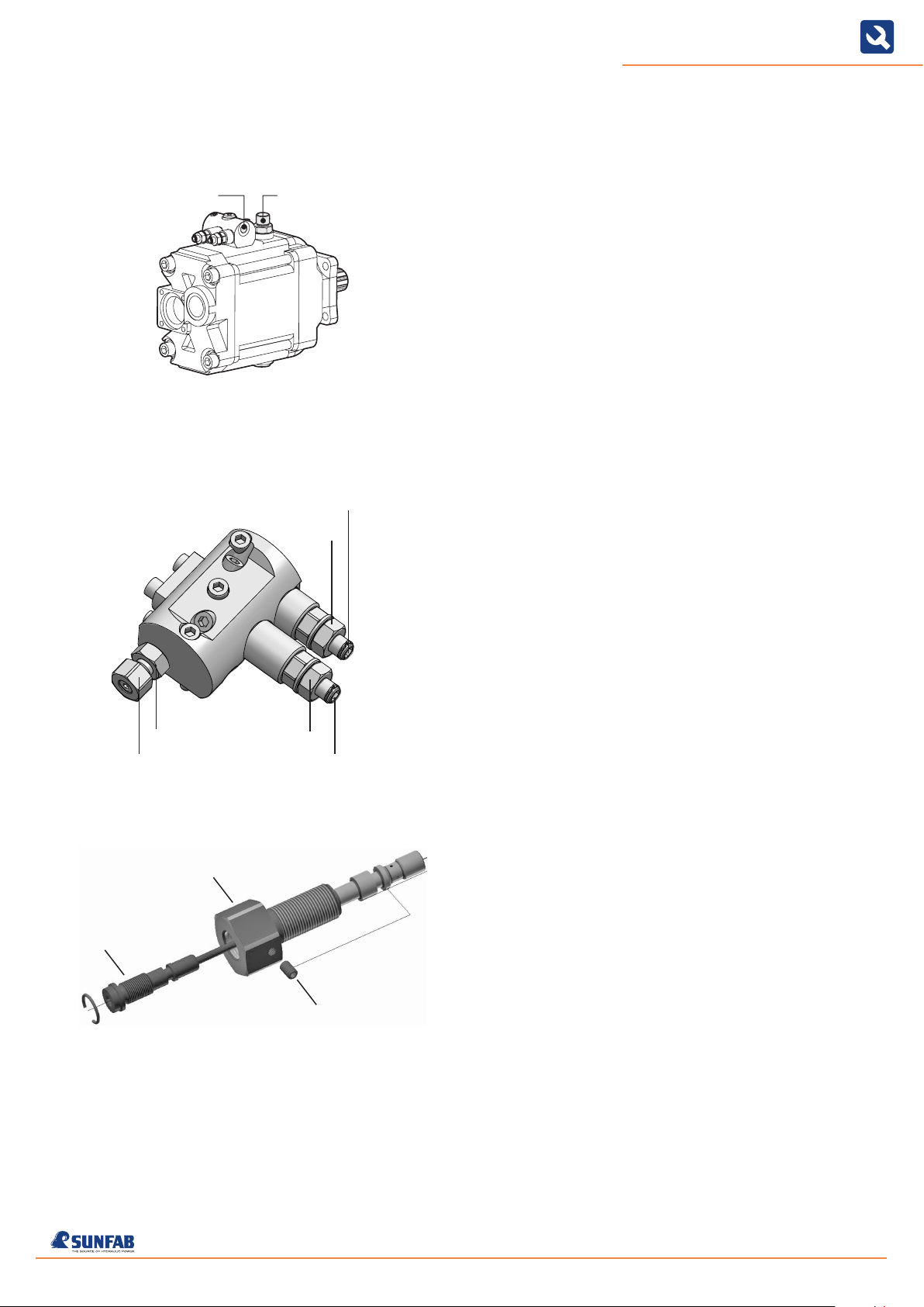
Load sensing regulator LSP
Adjust the differential pressure Δp = system pressure minus the signal pres-
sure. The regulation range is 20-55 bar. Preset to 27 bar. 1 turn of the
adjuster screw corresponds to 10 bar. Clockwise increases the differential
pressure, counterclockwise decreases.
Adjust the max. system pressure between 20 and 350 bar. The value preset
at the factory is 350 bar. 1 turn of the adjuster screw corresponds to 50
bar. Clockwise increases the maximum system pressure, counterclockwise
decreases.
Description of the two-part damping
screw on the LSP-controller
With the return flow throttle you can adjust the onstroke
time for bringing the pump from Vgmin to Vgmax.
• Unscrewing the screw reduces the dampening and accelerates the
vonstroke time.
• Screwing in the screw increases the dampening and slows down the
onstroke time.
• Adjustment range: ca. 5.5 revolutions resp. 4 mm
With the bypass throttle you can adjust the destroke time
for bringing the pump from Vgmax to Vgmin.
• Unscrewing the screw increases the dampening and slows down the
destroke time
• Screwing in the screw reduces the dampening and accelerates the
destroke time
• Adjustment range: ca. 4 revolutions resp. 2 mm
System pressure
Damping screw Differential pressure Δp
20 Nm
20 Nm 20 Nm
7015EN2008 Rev 1.4
Sunfab reserves the right to make changes in design and dimensions without notice. Printing and typesetting errors reserved.
Bypass throttle
Return flow throttle
Allen screw